ø12 a2 series miniature control units - idec · ø12 a2 series miniature control units short...
TRANSCRIPT
24
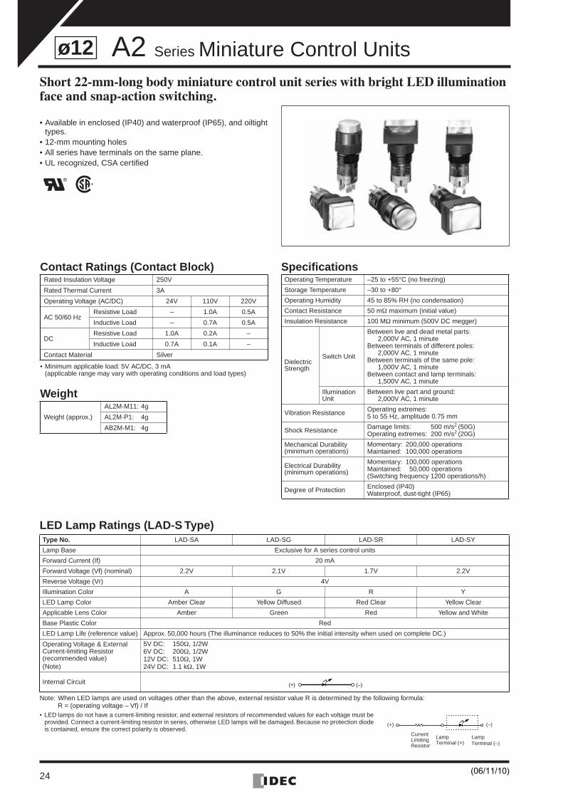
ø12 A2 Series Miniature Control UnitsShort 22-mm-long body miniature control unit series with bright LED illumination face and snap-action switching.
• Available in enclosed (IP40) and waterproof (IP65), and oiltight types.
• 12-mm mounting holes• All series have terminals on the same plane.• UL recognized, CSA certified
LED Lamp Ratings (LAD-S Type)
Note: When LED lamps are used on voltages other than the above, external resistor value R is determined by the following formula:R = (operating voltage – Vf) / If
• LED lamps do not have a current-limiting resistor, and external resistors of recommended values for each voltage must be provided. Connect a current-limiting resistor in series, otherwise LED lamps will be damaged. Because no protection diode is contained, ensure the correct polarity is observed.
Type No. LAD-SA LAD-SG LAD-SR LAD-SY
Lamp Base Exclusive for A series control units
Forward Current (If) 20 mA
Forward Voltage (Vf) (nominal) 2.2V 2.1V 1.7V 2.2V
Reverse Voltage (Vr) 4V
Illumination Color A G R Y
LED Lamp Color Amber Clear Yellow Diffused Red Clear Yellow Clear
Applicable Lens Color Amber Green Red Yellow and White
Base Plastic Color Red
LED Lamp Life (reference value) Approx. 50,000 hours (The illuminance reduces to 50% the initial intensity when used on complete DC.)
Operating Voltage & External Current-limiting Resistor(recommended value)(Note)
5V DC: 150Ω, 1/2W6V DC: 200Ω, 1/2W12V DC: 510Ω, 1W24V DC: 1.1 kΩ, 1W
Internal Circuit
Contact Ratings (Contact Block)
• Minimum applicable load: 5V AC/DC, 3 mA(applicable range may vary with operating conditions and load types)
Weight
Specifications Rated Insulation Voltage 250V
Rated Thermal Current 3A
Operating Voltage (AC/DC) 24V 110V 220V
AC 50/60 HzResistive Load – 1.0A 0.5A
Inductive Load – 0.7A 0.5A
DCResistive Load 1.0A 0.2A –
Inductive Load 0.7A 0.1A –
Contact Material Silver
Weight (approx.)
AL2M-M11: 4g
AL2M-P1: 4g
AB2M-M1: 4g
Operating Temperature –25 to +55°C (no freezing)
Storage Temperature –30 to +80°
Operating Humidity 45 to 85% RH (no condensation)
Contact Resistance 50 mΩ maximum (initial value)
Insulation Resistance 100 MΩ minimum (500V DC megger)
Dielectric Strength
Switch Unit
Between live and dead metal parts:2,000V AC, 1 minute
Between terminals of different poles:2,000V AC, 1 minute
Between terminals of the same pole:1,000V AC, 1 minute
Between contact and lamp terminals:1,500V AC, 1 minute
Illumination Unit
Between live part and ground:2,000V AC, 1 minute
Vibration Resistance Operating extremes:5 to 55 Hz, amplitude 0.75 mm
Shock Resistance Damage limits: 500 m/s2 (50G)Operating extremes: 200 m/s2 (20G)
Mechanical Durability(minimum operations)
Momentary: 200,000 operationsMaintained: 100,000 operations
Electrical Durability(minimum operations)
Momentary: 100,000 operationsMaintained: 50,000 operations(Switching frequency 1200 operations/h)
Degree of Protection Enclosed (IP40)Waterproof, dust-tight (IP65)
(+) (–)
(+)
LampTerminal (–)
LampTerminal (+)
(–)
CurrentLimitingResistor
(06/11/10)
A2 Series Miniature Control Units
25
ø12
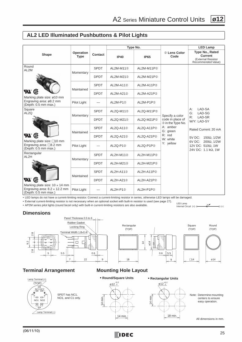
• LED lamps do not have a current-limiting resistor. Connect a current-limiting resistor in series, otherwise LED lamps will be damaged.• External current-limiting resistor is not necessary when an optional socket with built-in resistor is used (see page 27).• AP2M series pilot lights (round bezel only) with built-in current-limiting resistors are also available.
Dimensions
Terminal Arrangement Mounting Hole Layout
AL2 LED Illuminated Pushbuttons & Pilot Lights
Shape OperationType Contact
Type No.
➁ Lens Color Code
LED Lamp
IP40 IP65
Type No., Rated Current
(External Resistor Recommended Value)
RoundAL2M
Marking plate size: ø10 mmEngraving area: ø8.2 mm(Depth: 0.5 mm max.)
MomentarySPDT AL2M-M11➁ AL2M-M11P➁
Specify a color code in place of ➁ in the Type No. A: amberG: greenR: redW: whiteY: yellow
A: LAD-SAG: LAD-SGR: LAD-SRW/Y: LAD-SY
Rated Current: 20 mA
5V DC: 150Ω, 1/2W6V DC: 200Ω, 1/2W12V DC: 510Ω, 1W24V DC: 1.1 kΩ, 1W
DPDT AL2M-M21➁ AL2M-M21P➁
MaintainedSPDT AL2M-A11➁ AL2M-A11P➁
DPDT AL2M-A21➁ AL2M-A21P➁
Pilot Light — AL2M-P1➁ AL2M-P1P➁
SquareAL2Q
Marking plate size: �10 mmEngraving area: �8.2 mm(Depth: 0.5 mm max.)
MomentarySPDT AL2Q-M11➁ AL2Q-M11P➁
DPDT AL2Q-M21➁ AL2Q-M21P➁
MaintainedSPDT AL2Q-A11➁ AL2Q-A11P➁
DPDT AL2Q-A21➁ AL2Q-A21P➁
Pilot Light — AL2Q-P1➁ AL2Q-P1P➁
RectangularAL2H
Marking plate size: 10 × 14 mmEngraving area: 8.2 × 12.2 mm (Depth: 0.5 mm max.)
MomentarySPDT AL2H-M11➁ AL2H-M11P➁
DPDT AL2H-M21➁ AL2H-M21P➁
MaintainedSPDT AL2H-A11➁ AL2H-A11P➁
DPDT AL2H-A21➁ AL2H-A21P➁
Pilot Light — AL2H-P1➁ AL2H-P1P➁
(+) (–)Internal CircuitLED Lamp
2.8
2.8
9.2
5 5.5 0.6
7 22 9 18
14 ø14
0.6 5.5
9 c14 ø14
Rubber Gasket
Locking Ring(TOP)
Rectangular RoundSquare(TOP) (TOP)
Terminal Width 1.8×0.4t
Panel Thickness 0.5 to 6
NC1
NO1
C1
NC2
NO2
C2
Lamp Terminal (+)
Lamp Terminal (–)
(TOP) ø12 0+0.2
14 min.
14 m
in.
ø12 0+0.2
18 min.
14 m
in.SPDT has NC1,
NO1, and C1 only.
•••• Round/Square Units •••• Rectangular Units
All dimensions in mm.
Note: Determine mounting centers to ensure easy operation.
(06/11/10)
A2 Series Miniature Control Units
26
ø12
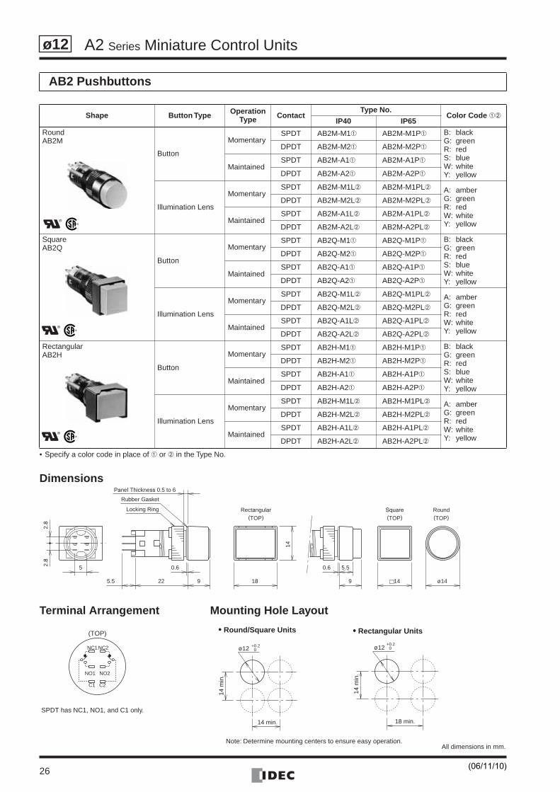
• Specify a color code in place of ➀ or ➁ in the Type No.
Dimensions
Terminal Arrangement Mounting Hole Layout
AB2 Pushbuttons
Shape Button Type OperationType Contact
Type No.Color Code ➀➁
IP40 IP65
RoundAB2M
Button
MomentarySPDT AB2M-M1➀ AB2M-M1P➀ B: black
G: greenR: redS: blueW: whiteY: yellow
DPDT AB2M-M2➀ AB2M-M2P➀
MaintainedSPDT AB2M-A1➀ AB2M-A1P➀
DPDT AB2M-A2➀ AB2M-A2P➀
Illumination Lens
MomentarySPDT AB2M-M1L➁ AB2M-M1PL➁ A: amber
G: greenR: redW: whiteY: yellow
DPDT AB2M-M2L➁ AB2M-M2PL➁
MaintainedSPDT AB2M-A1L➁ AB2M-A1PL➁
DPDT AB2M-A2L➁ AB2M-A2PL➁
SquareAB2Q
Button
MomentarySPDT AB2Q-M1➀ AB2Q-M1P➀ B: black
G: greenR: redS: blueW: whiteY: yellow
DPDT AB2Q-M2➀ AB2Q-M2P➀
MaintainedSPDT AB2Q-A1➀ AB2Q-A1P➀
DPDT AB2Q-A2➀ AB2Q-A2P➀
Illumination Lens
MomentarySPDT AB2Q-M1L➁ AB2Q-M1PL➁ A: amber
G: greenR: redW: whiteY: yellow
DPDT AB2Q-M2L➁ AB2Q-M2PL➁
MaintainedSPDT AB2Q-A1L➁ AB2Q-A1PL➁
DPDT AB2Q-A2L➁ AB2Q-A2PL➁
RectangularAB2H
Button
MomentarySPDT AB2H-M1➀ AB2H-M1P➀ B: black
G: greenR: redS: blueW: whiteY: yellow
DPDT AB2H-M2➀ AB2H-M2P➀
MaintainedSPDT AB2H-A1➀ AB2H-A1P➀
DPDT AB2H-A2➀ AB2H-A2P➀
Illumination Lens
MomentarySPDT AB2H-M1L➁ AB2H-M1PL➁ A: amber
G: greenR: redW: whiteY: yellow
DPDT AB2H-M2L➁ AB2H-M2PL➁
MaintainedSPDT AB2H-A1L➁ AB2H-A1PL➁
DPDT AB2H-A2L➁ AB2H-A2PL➁
2.8
2.8
5
5.5
0.6
22 9 18
14
0.6 5.5
9 c14 ø14
Rubber Gasket
Locking Ring
(TOP)Rectangular RoundSquare
(TOP) (TOP)
Panel Thickness 0.5 to 6
NC1
NO1
C1
NC2
NO2
C2
(TOP)
ø12 0+0.2
14 min.
14 m
in.
ø12 0+0.2
18 min.
14 m
in.
SPDT has NC1, NO1, and C1 only.
•••• Round/Square Units •••• Rectangular Units
All dimensions in mm.Note: Determine mounting centers to ensure easy operation.
(06/11/10)
A2 Series Miniature Control Units
27
ø12
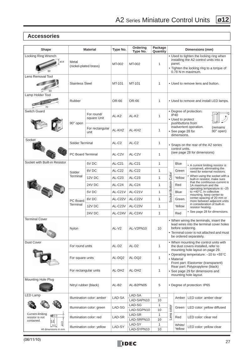
Accessories
Shape Material Type No. OrderingType No.
PackageQuantity Dimensions (mm)
Locking Ring Wrench
Metal(nickel-plated brass)
MT-002 MT-002 1
• Used to tighten the locking ring when installing the A2 control units into a panel.
• Tighten the locking ring to a torque of 0.78 N·m maximum.
Lens Removal Tool
Stainless Steel MT-101 MT-101 1 • Used to remove lens and button.
Lamp Holder Tool
Rubber OR-66 OR-66 1 • Used to remove and install LED lamps.
Switch Guard
90° open
For round/square Unit AL-K2 AL-K2 1
• Degree of protection: IP40
• Used to protect pushbuttons from inadvertent operation.
• See page 28 for dimensions.
For rectangularunit AL-KH2 AL-KH2 1
Solder Terminal AL-C2 AL-C2 1 • Snaps on the rear of the A2 series control units.(see page 28 for dimensions)PC Board Terminal AL-C2V AL-C2V 1
Socket with Built-in Resistor
SolderTerminal
5V DC AL-C21 AL-C21 1
Soc
ket B
otto
m C
olor
Blue • A current limiting resistor is contained, eliminating the need for external resistors.
• When using the socket with a built-in resistor, make sure that the continuous current is 1A maximum and the operating temperature is –25 to +40°C. In collective mounting, keep center-to center-spacing of 20 mm or more between adjacent units in consideration of built-in resistor heating.
• See page 28 for dimensions.
6V DC AL-C22 AL-C22 1 Green
12V DC AL-C23 AL-C23 1 Yellow
24V DC AL-C24 AL-C24 1 Red
PC BoardTerminal
5V DC AL-C21V AL-C21V 1 Blue
6V DC AL-C22V AL-C22V 1 Green
12V DC AL-C23V AL-C23V 1 Yellow
24V DC AL-C24V AL-C24V 1 Red
Terminal Cover
Nylon AL-V2 AL-V2PN10 10
• When wiring the terminals, insert the lead wires into the terminal cover holes before soldering.
• Terminal cover is not attached and must be ordered separately.
Dust CoverFor round units AL-D2 AL-D2 1
• When mounting the control units with the dust covers installed, refer to mounting hole layout on page 29.
• Operating temperature: –10 to +55°C• Material
Front part: Elastomer (transparent)Rear part: Polypropylene (black)
• See page 29 for dimensions and mounting hole layout.
For square units AL-DQ2 AL-DQ2 1
For rectangular units AL-DH2 AL-DH2 1
Mounting Hole Plug
Nitryl rubber (black) AL-B2 AL-B2PN05 5 • Degree of protection: IP65
LED LampIllumination color: amber LAD-SA
LAD-SA 1
Lens
col
or
Amber LED color: amber clearLAD-SAPN10 10
Illumination color: green LAD-SGLAD-SG 1
Green LED color: yellow diffusedLAD-SGPN10 10
Illumination color: red LAD-SRLAD-SR 1
Red LED color: clear redLAD-SRPN10 10
Illumination color: yellow LAD-SYLAD-SY 1 White/
Yellow LED color: yellow clearLAD-SYPN10 10
ø14
60
60
70
(remains 90° open)
Socket
5.3
9.0 ø4.
0
Current-limiting resistor is not contained.
All dimensions in mm.
(06/11/10)
A2 Series Miniature Control Units
28
ø12
Dimensions
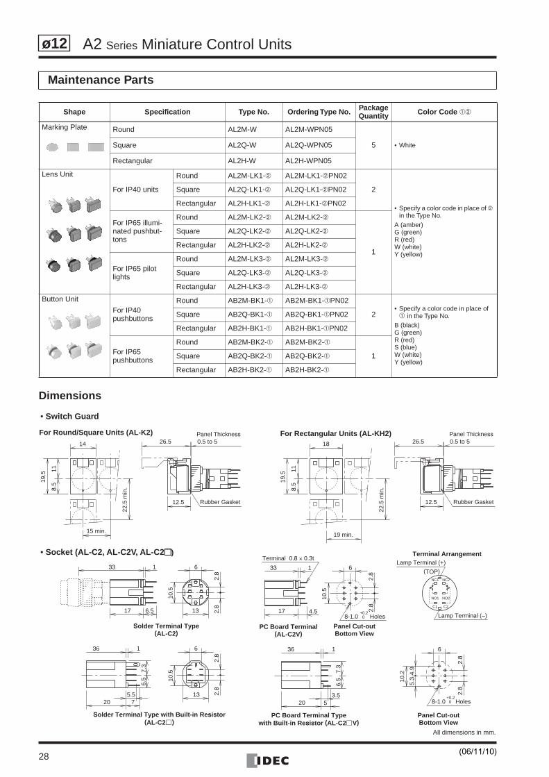
Maintenance Parts
Shape Specification Type No. Ordering Type No. PackageQuantity Color Code ➀➁
Marking Plate Round AL2M-W AL2M-WPN05
5 • WhiteSquare AL2Q-W AL2Q-WPN05
Rectangular AL2H-W AL2H-WPN05
Lens Unit
For IP40 units
Round AL2M-LK1-➁ AL2M-LK1-➁PN02
2
• Specify a color code in place of ➁ in the Type No.
A (amber)G (green)R (red)W (white)Y (yellow)
Square AL2Q-LK1-➁ AL2Q-LK1-➁PN02
Rectangular AL2H-LK1-➁ AL2H-LK1-➁PN02
For IP65 illumi-nated pushbut-tons
Round AL2M-LK2-➁ AL2M-LK2-➁
1
Square AL2Q-LK2-➁ AL2Q-LK2-➁
Rectangular AL2H-LK2-➁ AL2H-LK2-➁
For IP65 pilot lights
Round AL2M-LK3-➁ AL2M-LK3-➁
Square AL2Q-LK3-➁ AL2Q-LK3-➁
Rectangular AL2H-LK3-➁ AL2H-LK3-➁
Button Unit
For IP40pushbuttons
Round AB2M-BK1-➀ AB2M-BK1-➀PN02
2• Specify a color code in place of
➀ in the Type No.B (black)G (green)R (red)S (blue)W (white)Y (yellow)
Square AB2Q-BK1-➀ AB2Q-BK1-➀PN02
Rectangular AB2H-BK1-➀ AB2H-BK1-➀PN02
For IP65pushbuttons
Round AB2M-BK2-➀ AB2M-BK2-➀
1Square AB2Q-BK2-➀ AB2Q-BK2-➀
Rectangular AB2H-BK2-➀ AB2H-BK2-➀
8-1.0 Holes
Panel Cut-outBottom View
+0.20
2.8
2.8
6
4.9
5.310
.2
36
(AL-C2 c )Solder Terminal Type with Built-in Resistor
Solder Terminal Type(AL-C2)
17 6.5
33 1
13
10.5
6
2.8
2.8
5.57
10.5
2.8
2.8
13
6
7.3
6.5
20
1
PC Board Terminal Typewith Built-in Resistor (AL-C2 c V)
33
Terminal 0.8 × 0.3t
36
8-1.0 Holes
PC Board Terminal(AL-C2V)
Panel Cut-outBottom View
+0.20
6
10.5
17 4.5
20
7.3
6.5
1
3.55
2.8
2.8
1Lamp Terminal (+)
Lamp Terminal (–)
Terminal Arrangement
NC1 NC2
NO1 NO2
C1 C2
(TOP)
Rubber Gasket
Panel Thickness
12.5
26.5 0.5 to 5
8.5
11
19.5
19 min.
22.5
min
.
18
Rubber Gasket
Panel Thickness
12.5
26.5 0.5 to 514
8.5
11
19.5
22.5
min
.
15 min.
• Switch Guard
• Socket (AL-C2, AL-C2V, AL-C2����)
For Round/Square Units (AL-K2) For Rectangular Units (AL-KH2)
All dimensions in mm.
(06/11/10)
A2 Series Miniature Control Units
29
ø12
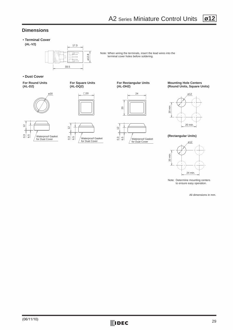
Dimensions
17.3
33.5
ø12
.8
Waterproof Gasketfor Dust Cover
ø20
6.5
120.
3
6.5
120.
3
c 20
Waterproof Gasketfor Dust Cover
6.5
120.
3
24
20
Waterproof Gasketfor Dust Cover
ø12
20 min.
20 m
in.
ø12
24 min.20
min
.
• Terminal Cover(AL-V2)
• Dust Cover
For Round Units(AL-D2)
For Square Units(AL-DQ2)
For Rectangular Units(AL-DH2)
Mounting Hole Centers(Round Units, Square Units)
(Rectangular Units)
Note: When wiring the terminals, insert the lead wires into the terminal cover holes before soldering.
Note: Determine mounting centers to ensure easy operation.
All dimensions in mm.
(06/11/10)
A2 Series Miniature Control Units
30
ø12
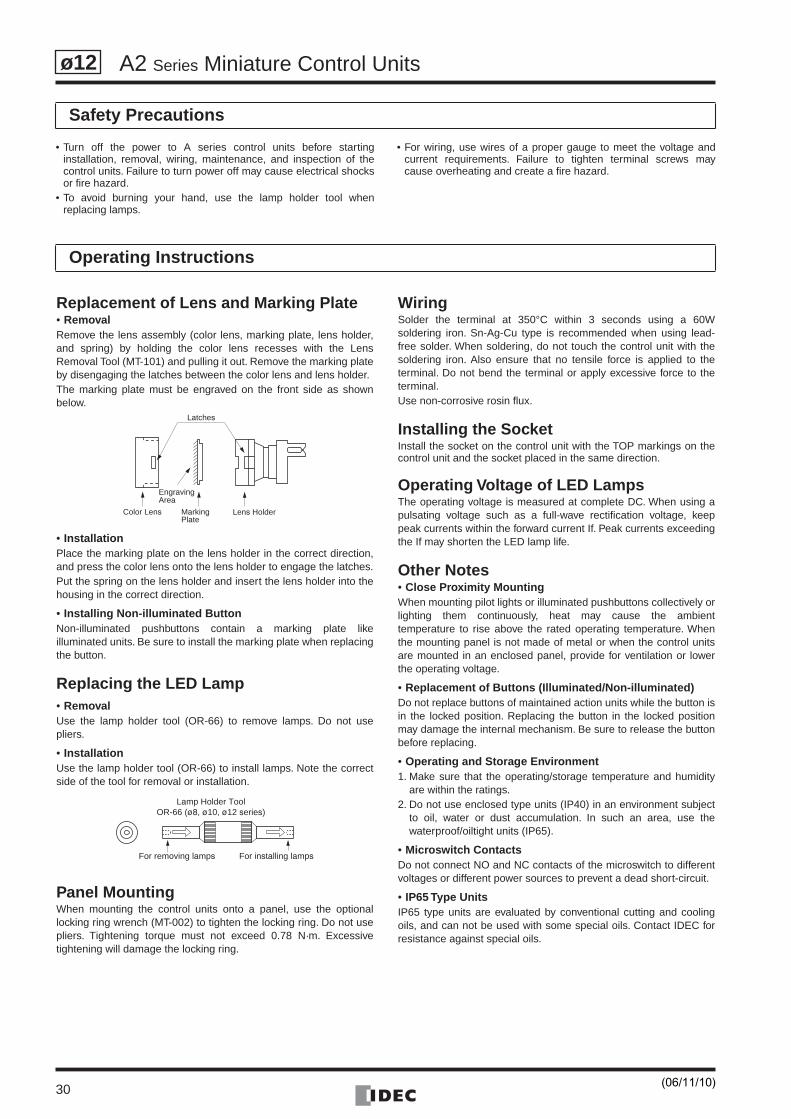
Safety Precautions
Operating Instructions
• Turn off the power to A series control units before startinginstallation, removal, wiring, maintenance, and inspection of thecontrol units. Failure to turn power off may cause electrical shocksor fire hazard.
• To avoid burning your hand, use the lamp holder tool whenreplacing lamps.
• For wiring, use wires of a proper gauge to meet the voltage andcurrent requirements. Failure to tighten terminal screws maycause overheating and create a fire hazard.
Replacement of Lens and Marking Plate• RemovalRemove the lens assembly (color lens, marking plate, lens holder,and spring) by holding the color lens recesses with the LensRemoval Tool (MT-101) and pulling it out. Remove the marking plateby disengaging the latches between the color lens and lens holder.The marking plate must be engraved on the front side as shownbelow.
• InstallationPlace the marking plate on the lens holder in the correct direction,and press the color lens onto the lens holder to engage the latches.Put the spring on the lens holder and insert the lens holder into thehousing in the correct direction.
• Installing Non-illuminated ButtonNon-illuminated pushbuttons contain a marking plate likeilluminated units. Be sure to install the marking plate when replacingthe button.
Replacing the LED Lamp• RemovalUse the lamp holder tool (OR-66) to remove lamps. Do not usepliers.
• InstallationUse the lamp holder tool (OR-66) to install lamps. Note the correctside of the tool for removal or installation.
Panel MountingWhen mounting the control units onto a panel, use the optionallocking ring wrench (MT-002) to tighten the locking ring. Do not usepliers. Tightening torque must not exceed 0.78 N·m. Excessivetightening will damage the locking ring.
WiringSolder the terminal at 350°C within 3 seconds using a 60Wsoldering iron. Sn-Ag-Cu type is recommended when using lead-free solder. When soldering, do not touch the control unit with thesoldering iron. Also ensure that no tensile force is applied to theterminal. Do not bend the terminal or apply excessive force to theterminal.Use non-corrosive rosin flux.
Installing the SocketInstall the socket on the control unit with the TOP markings on thecontrol unit and the socket placed in the same direction.
Operating Voltage of LED LampsThe operating voltage is measured at complete DC. When using apulsating voltage such as a full-wave rectification voltage, keeppeak currents within the forward current If. Peak currents exceedingthe If may shorten the LED lamp life.
Other Notes• Close Proximity MountingWhen mounting pilot lights or illuminated pushbuttons collectively orlighting them continuously, heat may cause the ambienttemperature to rise above the rated operating temperature. Whenthe mounting panel is not made of metal or when the control unitsare mounted in an enclosed panel, provide for ventilation or lowerthe operating voltage.
• Replacement of Buttons (Illuminated/Non-illuminated)Do not replace buttons of maintained action units while the button isin the locked position. Replacing the button in the locked positionmay damage the internal mechanism. Be sure to release the buttonbefore replacing.
• Operating and Storage Environment1. Make sure that the operating/storage temperature and humidity
are within the ratings.2. Do not use enclosed type units (IP40) in an environment subject
to oil, water or dust accumulation. In such an area, use thewaterproof/oiltight units (IP65).
• Microswitch ContactsDo not connect NO and NC contacts of the microswitch to differentvoltages or different power sources to prevent a dead short-circuit.
• IP65 Type UnitsIP65 type units are evaluated by conventional cutting and coolingoils, and can not be used with some special oils. Contact IDEC forresistance against special oils.
Latches
EngravingArea
Color Lens MarkingPlate
Lens Holder
Lamp Holder ToolOR-66 (ø8, ø10, ø12 series)
For removing lamps For installing lamps
(06/11/10)
31
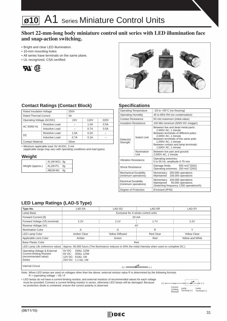
A1 Series Miniature Control UnitsShort 22-mm-long body miniature control unit series with LED illumination face and snap-action switching.
• Bright and clear LED illumination.• 10-mm mounting holes• All series have terminals on the same plane.• UL recognized, CSA certified
LED Lamp Ratings (LAD-S Type)
Note: When LED lamps are used on voltages other than the above, external resistor value R is determined by the following formula:R = (operating voltage – Vf) / If
• LED lamps do not have a current-limiting resistor, and external resistors of recommended values for each voltage must be provided. Connect a current-limiting resistor in series, otherwise LED lamps will be damaged. Because no protection diode is contained, ensure the correct polarity is observed.
Type No. LAD-SA LAD-SG LAD-SR LAD-SY
Lamp Base Exclusive for A series control units
Forward Current (If) 20 mA
Forward Voltage (Vf) (nominal) 2.2V 2.1V 1.7V 2.2V
Reverse Voltage (Vr) 4V
Illumination Color A G R Y
LED Lamp Color Amber Clear Yellow Diffused Red Clear Yellow Clear
Applicable Lens Color Amber Green Red Yellow and White
Base Plastic Color Red
LED Lamp Life (reference value) Approx. 50,000 hours (The illuminance reduces to 50% the initial intensity when used on complete DC.)
Operating Voltage & External Current-limiting Resistor(recommended value)(Note)
5V DC: 150Ω, 1/2W6V DC: 200Ω, 1/2W12V DC: 510Ω, 1W24V DC: 1.1 kΩ, 1W
Internal Circuit
Contact Ratings (Contact Block)
• Minimum applicable load: 5V AC/DC, 3 mA(applicable range may vary with operating conditions and load types)
Weight
Specifications Rated Insulation Voltage 250V
Rated Thermal Current 3A
Operating Voltage (AC/DC) 24V 110V 220V
AC 50/60 HzResistive Load – 1.0A 0.5A
Inductive Load – 0.7A 0.5A
DCResistive Load 1.0A 0.2A –
Inductive Load 0.7A 0.1A –
Contact Material Silver
Weight (approx.)
AL1M-M11: 3g
AL1M-P1: 3g
AB1M-M1: 3g
Operating Temperature –25 to +55°C (no freezing)
Operating Humidity 45 to 85% RH (no condensation)
Contact Resistance 50 mΩ maximum (initial value)
Insulation Resistance 100 MΩ minimum (500V DC megger)
Dielectric Strength
Switch Unit
Between live and dead metal parts:2,000V AC, 1 minute
Between terminals of different poles:2,000V AC, 1 minute
Between terminals of the same pole:1,000V AC, 1 minute
Between contact and lamp terminals:1,500V AC, 1 minute
Illumination Unit
Between live part and ground:2,000V AC, 1 minute
Vibration Resistance Operating extremes:5 to 55 Hz, amplitude 0.75 mm
Shock Resistance Damage limits: 500 m/s2 (50G)Operating extremes: 200 m/s2 (20G)
Mechanical Durability(minimum operations)
Momentary: 200,000 operationsMaintained: 100,000 operations
Electrical Durability(minimum operations)
Momentary: 100,000 operationsMaintained: 50,000 operations(Switching frequency 1200 operations/h)
Degree of Protection Enclosed (IP40)
(+) (–)
(+)
LampTerminal (–)
LampTerminal (+)
(–)
CurrentLimitingResistor
ø10
(06/11/10)
A1 Series Miniature Control Units
32
ø10
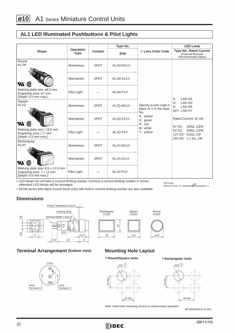
• LED lamps do not have a current-limiting resistor. Connect a current-limiting resistor in series, otherwise LED lamps will be damaged.
• AP1M series pilot lights (round bezel only) with built-in current-limiting resistor are also available.
Dimensions
Terminal Arrangement (bottom view) Mounting Hole Layout
AL1 LED Illuminated Pushbuttons & Pilot Lights
Shape OperationType Contact
Type No.
➁ Lens Color Code
LED Lamp
IP40Type No., Rated Current
(External Resistor Recommended Value)
RoundAL1M
Marking plate size: ø8.5 mmEngraving area: ø7 mm(Depth: 0.5 mm max.)
Momentary SPDT AL1M-M11➁
Specify a color code in place of ➁ in the Type No. A: amberG: greenR: redW: whiteY: yellow
A: LAD-SAG: LAD-SGR: LAD-SRW/Y: LAD-SY
Rated Current: 20 mA
5V DC: 150Ω, 1/2W6V DC: 200Ω, 1/2W12V DC: 510Ω, 1W24V DC: 1.1 kΩ, 1W
Maintained SPDT AL1M-A11➁
Pilot Light — AL1M-P1➁
SquareAL1Q
Marking plate size: �8.5 mmEngraving area: �7 mm(Depth: 0.5 mm max.)
Momentary SPDT AL1Q-M11➁
Maintained SPDT AL1Q-A11➁
Pilot Light — AL1Q-P1➁
RectangularAL1H
Marking plate size: 8.5 × 12.5 mmEngraving area: 7 × 11 mm (Depth: 0.5 mm max.)
Momentary SPDT AL1H-M11➁
Maintained SPDT AL1H-A11➁
Pilot Light — AL1H-P1➁
(+) (–)Internal CircuitLED Lamp
Locking Ring Round(TOP)
Rectangular(TOP)
Square(TOP)
2.8
2.8
6
Panel Thickness 0.5 to 6
5.5
5.5 22 9
16
12
c12 ø12ø12
Terminal Width 1.8×0.4t
•••• Round/Square Units •••• Rectangular Units
All dimensions in mm.
ø10 0+0.2
12 min.
12 m
in.
ø10 0+0.2
16 min.
12 m
in.
NC
NO
COMLampTerminal (+)
LampTerminal (–)
(TOP)
Note: Determine mounting centers to ensure easy operation.
(06/11/10)
A1 Series Miniature Control Units
33
ø10
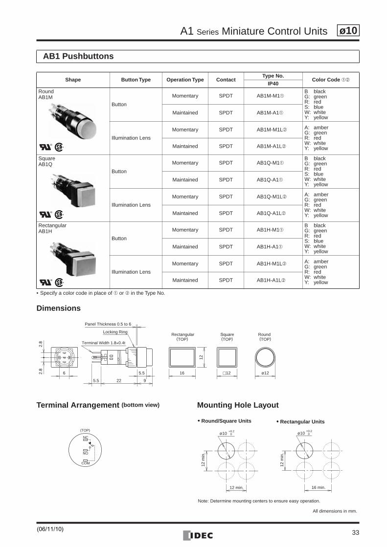
• Specify a color code in place of ➀ or ➁ in the Type No.
Dimensions
Terminal Arrangement (bottom view) Mounting Hole Layout
AB1 Pushbuttons
Shape Button Type Operation Type ContactType No.
Color Code ➀➁IP40
RoundAB1M
Button
Momentary SPDT AB1M-M1➀B blackG: greenR: redS: blueW: whiteY: yellow
Maintained SPDT AB1M-A1➀
Illumination Lens
Momentary SPDT AB1M-M1L➁ A: amberG: greenR: redW: whiteY: yellowMaintained SPDT AB1M-A1L➁
SquareAB1Q
Button
Momentary SPDT AB1Q-M1➀B blackG: greenR: redS: blueW: whiteY: yellow
Maintained SPDT AB1Q-A1➀
Illumination Lens
Momentary SPDT AB1Q-M1L➁ A: amberG: greenR: redW: whiteY: yellowMaintained SPDT AB1Q-A1L➁
RectangularAB1H
Button
Momentary SPDT AB1H-M1➀B blackG: greenR: redS: blueW: whiteY: yellow
Maintained SPDT AB1H-A1➀
Illumination Lens
Momentary SPDT AB1H-M1L➁ A: amberG: greenR: redW: whiteY: yellowMaintained SPDT AB1H-A1L➁
2.8
2.8
6 5.5
5.5 22 9
16
12
c12 ø12
Locking RingRound(TOP)
Rectangular(TOP)
Square(TOP)
Panel Thickness 0.5 to 6
Terminal Width 1.8×0.4t
ø10 0+0.2
12 min.
12 m
in.
ø10 0+0.2
16 min.
12 m
in.
•••• Round/Square Units •••• Rectangular Units
All dimensions in mm.
NC
NO
COM
(TOP)
Note: Determine mounting centers to ensure easy operation.
(06/11/10)
A1 Series Miniature Control Units
34
ø10
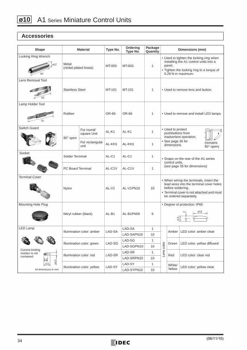
Accessories
Shape Material Type No. OrderingType No.
PackageQuantity Dimensions (mm)
Locking Ring Wrench
Metal(nickel-plated brass) MT-003 MT-003 1
• Used to tighten the locking ring when installing the A1 control units into a panel.
• Tighten the locking ring to a torque of 0.29 N·m maximum.
Lens Removal Tool
Stainless Steel MT-101 MT-101 1 • Used to remove lens and button.
Lamp Holder Tool
Rubber OR-66 OR-66 1 • Used to remove and install LED lamps.
Switch Guard
90° open
For round/square Unit AL-K1 AL-K1 1
• Used to protect pushbuttons from inadvertent operation.
• See page 35 for dimensions.
For rectangularunit AL-KH1 AL-KH1 1
Solder Terminal AL-C1 AL-C1 1• Snaps on the rear of the A1 series
control units.(see page 35 for dimensions)
PC Board Terminal AL-C1V AL-C1V 1
Terminal Cover
Nylon AL-V1 AL-V1PN10 10
• When wiring the terminals, insert the lead wires into the terminal cover holes before soldering.
• Terminal cover is not attached and must be ordered separately.
Mounting Hole Plug
Nitryl rubber (black) AL-B1 AL-B1PN05 5
• Degree of protection: IP65
LED LampIllumination color: amber LAD-SA
LAD-SA 1
Lens
col
or
Amber LED color: amber clearLAD-SAPN10 10
Illumination color: green LAD-SGLAD-SG 1
Green LED color: yellow diffusedLAD-SGPN10 10
Illumination color: red LAD-SRLAD-SR 1
Red LED color: clear redLAD-SRPN10 10
Illumination color: yellow LAD-SYLAD-SY 1 White/
Yellow LED color: yellow clearLAD-SYPN10 10
ø12
60
60
70
(remains 90° open)
Socket
4.4
2 ø12
5.3
9.0 ø4.
0
Current-limiting resistor is not contained.
All dimensions in mm.
(06/11/10)
A1 Series Miniature Control Units
35
ø10
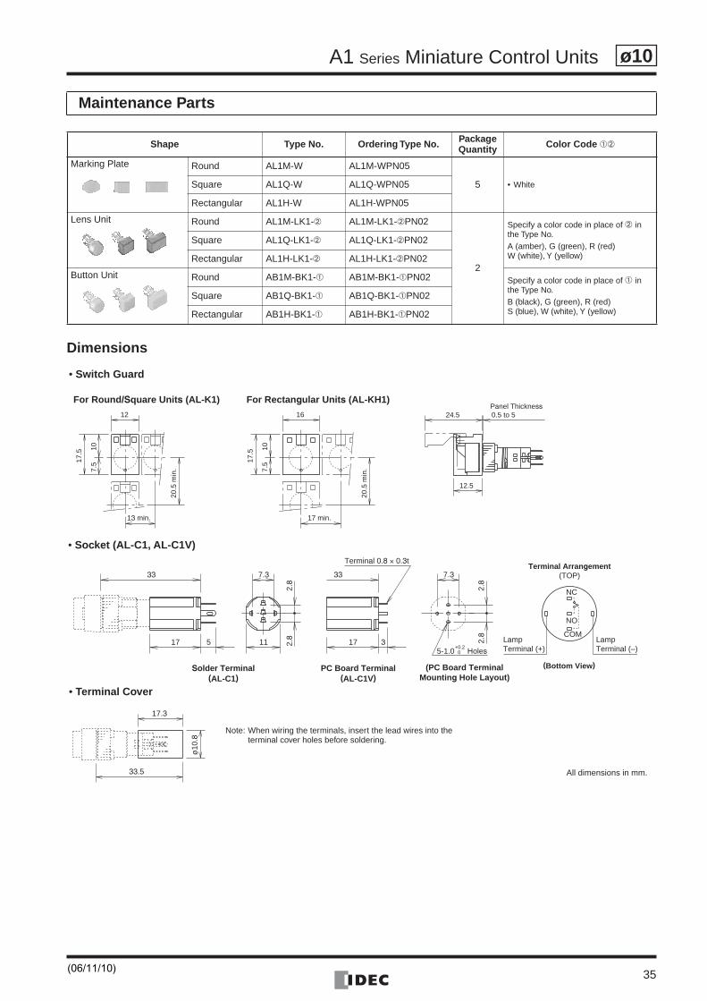
Dimensions
Maintenance Parts
Shape Type No. Ordering Type No. PackageQuantity Color Code ➀➁
Marking Plate Round AL1M-W AL1M-WPN05
5 • WhiteSquare AL1Q-W AL1Q-WPN05
Rectangular AL1H-W AL1H-WPN05
Lens Unit Round AL1M-LK1-➁ AL1M-LK1-➁PN02
2
Specify a color code in place of ➁ in the Type No.A (amber), G (green), R (red)W (white), Y (yellow)
Square AL1Q-LK1-➁ AL1Q-LK1-➁PN02
Rectangular AL1H-LK1-➁ AL1H-LK1-➁PN02
Button Unit Round AB1M-BK1-➀ AB1M-BK1-➀PN02 Specify a color code in place of ➀ in the Type No.B (black), G (green), R (red)S (blue), W (white), Y (yellow)
Square AB1Q-BK1-➀ AB1Q-BK1-➀PN02
Rectangular AB1H-BK1-➀ AB1H-BK1-➀PN02
Panel ThicknessFor Round/Square Units (AL-K1) For Rectangular Units (AL-KH1)
24.5 0.5 to 5
12.5
107.
517.5
20.5
min
.
12
13 min.
107.
517.5
20.5
min
.
16
17 min.
33
Terminal 0.8 × 0.3t
LampTerminal (–)
LampTerminal (+)
Terminal Arrangement(TOP)
5-1.0 Holes
Solder Terminal(AL-C1)
PC Board Terminal(AL-C1V)
(PC Board TerminalMounting Hole Layout)
(Bottom View)
NC
NO
COM
+0.20
17
33
17
2.8
2.8
2.8
2.8
5
7.3
3
7.3
11
17.3
33.5
ø10
.8
• Switch Guard
• Socket (AL-C1, AL-C1V)
• Terminal Cover
Note: When wiring the terminals, insert the lead wires into the terminal cover holes before soldering.
All dimensions in mm.
(06/11/10)
A1 Series Miniature Control Units
36
ø10
Safety Precautions
Operating Instructions
• Turn off the power to A series control units before startinginstallation, removal, wiring, maintenance, and inspection of thecontrol units. Failure to turn power off may cause electrical shocksor fire hazard.
• To avoid burning your hand, use the lamp holder tool whenreplacing lamps.
• For wiring, use wires of a proper gauge to meet the voltage andcurrent requirements. Failure to tighten terminal screws maycause overheating and create a fire hazard.
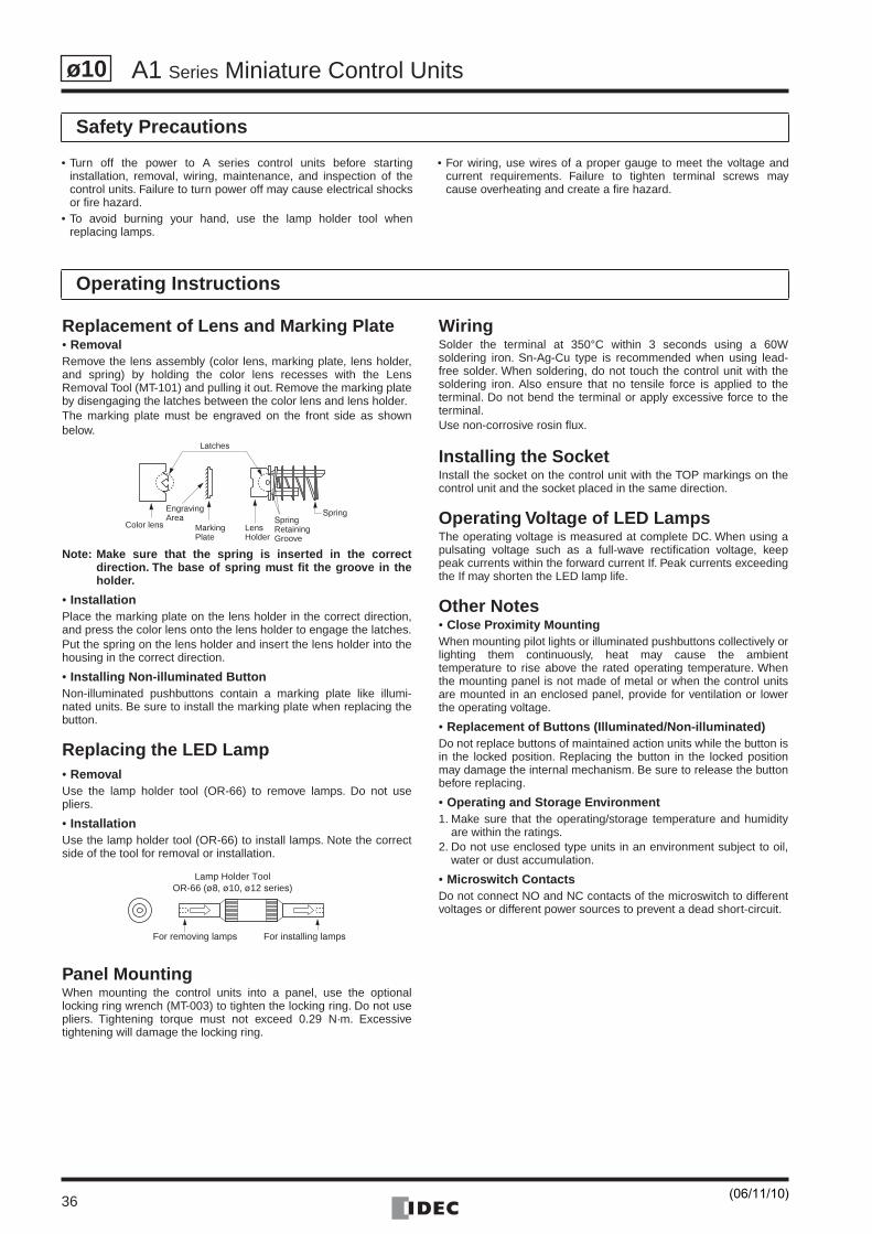
Replacement of Lens and Marking Plate• RemovalRemove the lens assembly (color lens, marking plate, lens holder,and spring) by holding the color lens recesses with the LensRemoval Tool (MT-101) and pulling it out. Remove the marking plateby disengaging the latches between the color lens and lens holder.The marking plate must be engraved on the front side as shownbelow.
Note: Make sure that the spring is inserted in the correctdirection. The base of spring must fit the groove in theholder.
• InstallationPlace the marking plate on the lens holder in the correct direction,and press the color lens onto the lens holder to engage the latches.Put the spring on the lens holder and insert the lens holder into thehousing in the correct direction.
• Installing Non-illuminated ButtonNon-illuminated pushbuttons contain a marking plate like illumi-nated units. Be sure to install the marking plate when replacing thebutton.
Replacing the LED Lamp• RemovalUse the lamp holder tool (OR-66) to remove lamps. Do not usepliers.
• InstallationUse the lamp holder tool (OR-66) to install lamps. Note the correctside of the tool for removal or installation.
Panel MountingWhen mounting the control units into a panel, use the optionallocking ring wrench (MT-003) to tighten the locking ring. Do not usepliers. Tightening torque must not exceed 0.29 N·m. Excessivetightening will damage the locking ring.
WiringSolder the terminal at 350°C within 3 seconds using a 60Wsoldering iron. Sn-Ag-Cu type is recommended when using lead-free solder. When soldering, do not touch the control unit with thesoldering iron. Also ensure that no tensile force is applied to theterminal. Do not bend the terminal or apply excessive force to theterminal.Use non-corrosive rosin flux.
Installing the SocketInstall the socket on the control unit with the TOP markings on thecontrol unit and the socket placed in the same direction.
Operating Voltage of LED LampsThe operating voltage is measured at complete DC. When using apulsating voltage such as a full-wave rectification voltage, keeppeak currents within the forward current If. Peak currents exceedingthe If may shorten the LED lamp life.
Other Notes• Close Proximity MountingWhen mounting pilot lights or illuminated pushbuttons collectively orlighting them continuously, heat may cause the ambienttemperature to rise above the rated operating temperature. Whenthe mounting panel is not made of metal or when the control unitsare mounted in an enclosed panel, provide for ventilation or lowerthe operating voltage.
• Replacement of Buttons (Illuminated/Non-illuminated)Do not replace buttons of maintained action units while the button isin the locked position. Replacing the button in the locked positionmay damage the internal mechanism. Be sure to release the buttonbefore replacing.
• Operating and Storage Environment1. Make sure that the operating/storage temperature and humidity
are within the ratings.2. Do not use enclosed type units in an environment subject to oil,
water or dust accumulation.
• Microswitch ContactsDo not connect NO and NC contacts of the microswitch to differentvoltages or different power sources to prevent a dead short-circuit.
Latches
Color lens
EngravingArea
MarkingPlate
LensHolder
SpringRetainingGroove
Spring
Lamp Holder ToolOR-66 (ø8, ø10, ø12 series)
For removing lamps For installing lamps
(06/11/10)
37
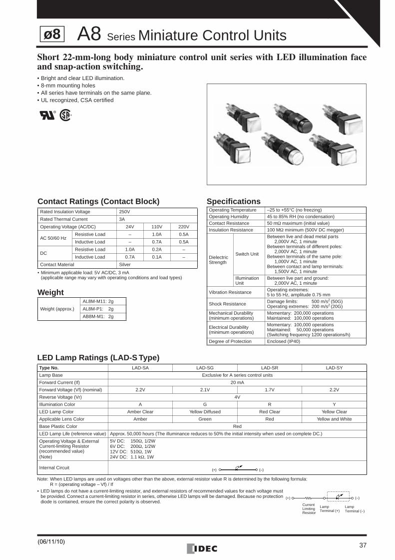
A8 Series Miniature Control UnitsShort 22-mm-long body miniature control unit series with LED illumination faceand snap-action switching.• Bright and clear LED illumination.• 8-mm mounting holes• All series have terminals on the same plane.• UL recognized, CSA certified
LED Lamp Ratings (LAD-S Type)
Note: When LED lamps are used on voltages other than the above, external resistor value R is determined by the following formula:R = (operating voltage – Vf) / If
• LED lamps do not have a current-limiting resistor, and external resistors of recommended values for each voltage must be provided. Connect a current-limiting resistor in series, otherwise LED lamps will be damaged. Because no protection diode is contained, ensure the correct polarity is observed.
Type No. LAD-SA LAD-SG LAD-SR LAD-SY
Lamp Base Exclusive for A series control units
Forward Current (If) 20 mA
Forward Voltage (Vf) (nominal) 2.2V 2.1V 1.7V 2.2V
Reverse Voltage (Vr) 4V
Illumination Color A G R Y
LED Lamp Color Amber Clear Yellow Diffused Red Clear Yellow Clear
Applicable Lens Color Amber Green Red Yellow and White
Base Plastic Color Red
LED Lamp Life (reference value) Approx. 50,000 hours (The illuminance reduces to 50% the initial intensity when used on complete DC.)
Operating Voltage & External Current-limiting Resistor(recommended value)(Note)
5V DC: 150Ω, 1/2W6V DC: 200Ω, 1/2W12V DC: 510Ω, 1W24V DC: 1.1 kΩ, 1W
Internal Circuit
Contact Ratings (Contact Block)
• Minimum applicable load: 5V AC/DC, 3 mA(applicable range may vary with operating conditions and load types)
Weight
Specifications Rated Insulation Voltage 250V
Rated Thermal Current 3A
Operating Voltage (AC/DC) 24V 110V 220V
AC 50/60 HzResistive Load – 1.0A 0.5A
Inductive Load – 0.7A 0.5A
DCResistive Load 1.0A 0.2A –
Inductive Load 0.7A 0.1A –
Contact Material Silver
Weight (approx.)
AL8M-M11: 2g
AL8M-P1: 2g
AB8M-M1: 2g
Operating Temperature –25 to +55°C (no freezing)Operating Humidity 45 to 85% RH (no condensation)Contact Resistance 50 mΩ maximum (initial value)Insulation Resistance 100 MΩ minimum (500V DC megger)
Dielectric Strength
Switch Unit
Between live and dead metal parts2,000V AC, 1 minute
Between terminals of different poles:2,000V AC, 1 minute
Between terminals of the same pole:1,000V AC, 1 minute
Between contact and lamp terminals:1,500V AC, 1 minute
Illumination Unit
Between live part and ground:2,000V AC, 1 minute
Vibration Resistance Operating extremes:5 to 55 Hz, amplitude 0.75 mm
Shock Resistance Damage limits: 500 m/s2 (50G)Operating extremes: 200 m/s2 (20G)
Mechanical Durability(minimum operations)
Momentary: 200,000 operationsMaintained: 100,000 operations
Electrical Durability(minimum operations)
Momentary: 100,000 operationsMaintained: 50,000 operations(Switching frequency 1200 operations/h)
Degree of Protection Enclosed (IP40)
(+) (–)
(+)
LampTerminal (–)
LampTerminal (+)
(–)
CurrentLimitingResistor
ø8
(06/11/10)
A8 Series Miniature Control Units
38
ø8
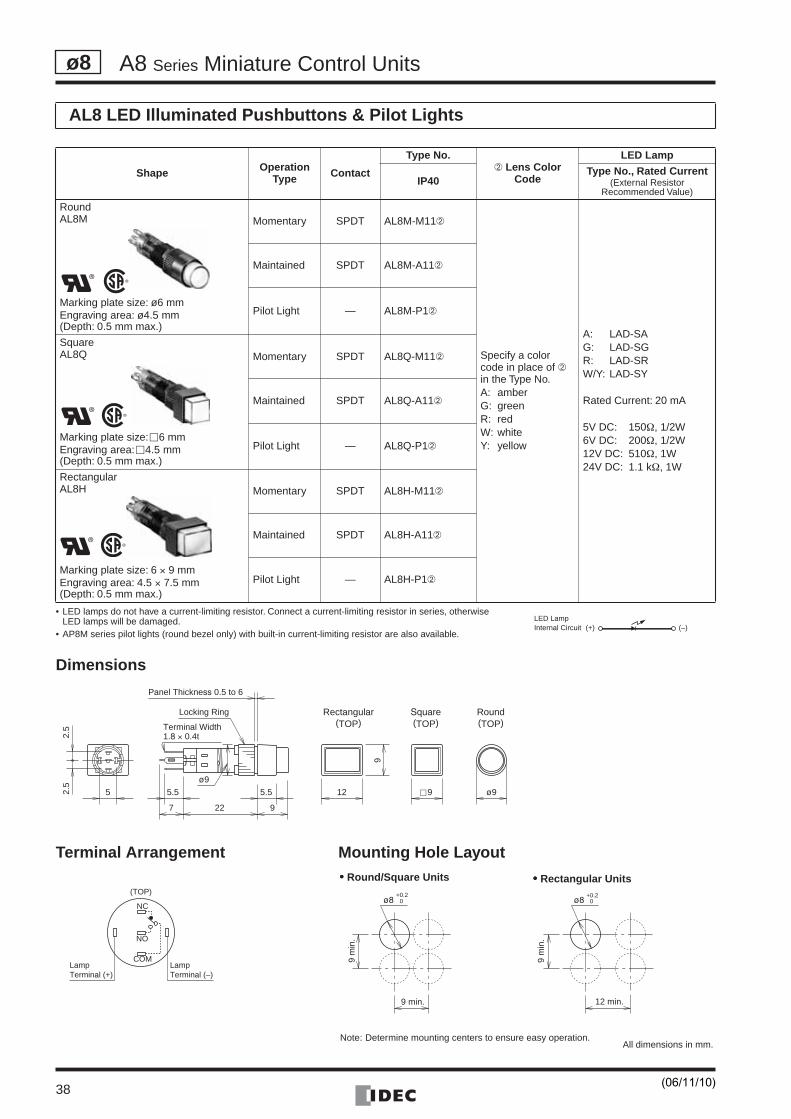
• LED lamps do not have a current-limiting resistor. Connect a current-limiting resistor in series, otherwise LED lamps will be damaged.
• AP8M series pilot lights (round bezel only) with built-in current-limiting resistor are also available.
Dimensions
Terminal Arrangement Mounting Hole Layout
AL8 LED Illuminated Pushbuttons & Pilot Lights
Shape OperationType Contact
Type No.➁ Lens Color
Code
LED Lamp
IP40Type No., Rated Current
(External Resistor Recommended Value)
RoundAL8M
Marking plate size: ø6 mmEngraving area: ø4.5 mm(Depth: 0.5 mm max.)
Momentary SPDT AL8M-M11➁
Specify a color code in place of ➁ in the Type No. A: amberG: greenR: redW: whiteY: yellow
A: LAD-SAG: LAD-SGR: LAD-SRW/Y: LAD-SY
Rated Current: 20 mA
5V DC: 150Ω, 1/2W6V DC: 200Ω, 1/2W12V DC: 510Ω, 1W24V DC: 1.1 kΩ, 1W
Maintained SPDT AL8M-A11➁
Pilot Light — AL8M-P1➁
SquareAL8Q
Marking plate size: �6 mmEngraving area: �4.5 mm(Depth: 0.5 mm max.)
Momentary SPDT AL8Q-M11➁
Maintained SPDT AL8Q-A11➁
Pilot Light — AL8Q-P1➁
RectangularAL8H
Marking plate size: 6 × 9 mmEngraving area: 4.5 × 7.5 mm(Depth: 0.5 mm max.)
Momentary SPDT AL8H-M11➁
Maintained SPDT AL8H-A11➁
Pilot Light — AL8H-P1➁
(+) (–)Internal CircuitLED Lamp
Locking Ring Round(TOP)
Panel Thickness 0.5 to 6
Rectangular(TOP)
Square(TOP)
5.55.5
22 9
2.5
2.5
5
7
12
9
c 9 ø9
ø9
Terminal Width1.8 × 0.4t
•••• Round/Square Units •••• Rectangular Units
All dimensions in mm.
ø8+0.2
0
9 min.
9 m
in.
ø8+0.2
0
12 min.
9 m
in.
NC
NO
COMLampTerminal (+)
LampTerminal (–)
(TOP)
Note: Determine mounting centers to ensure easy operation.
(06/11/10)
A8 Series Miniature Control Units
39
ø8
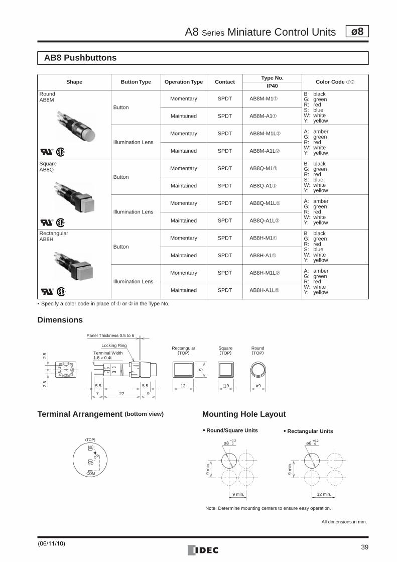
• Specify a color code in place of ➀ or ➁ in the Type No.
Dimensions
Terminal Arrangement (bottom view) Mounting Hole Layout
AB8 Pushbuttons
Shape Button Type Operation Type ContactType No.
Color Code ➀➁IP40
RoundAB8M
Button
Momentary SPDT AB8M-M1➀B blackG: greenR: redS: blueW: whiteY: yellow
Maintained SPDT AB8M-A1➀
Illumination Lens
Momentary SPDT AB8M-M1L➁ A: amberG: greenR: redW: whiteY: yellowMaintained SPDT AB8M-A1L➁
SquareAB8Q
Button
Momentary SPDT AB8Q-M1➀B blackG: greenR: redS: blueW: whiteY: yellow
Maintained SPDT AB8Q-A1➀
Illumination Lens
Momentary SPDT AB8Q-M1L➁ A: amberG: greenR: redW: whiteY: yellowMaintained SPDT AB8Q-A1L➁
RectangularAB8H
Button
Momentary SPDT AB8H-M1➀B blackG: greenR: redS: blueW: whiteY: yellow
Maintained SPDT AB8H-A1➀
Illumination Lens
Momentary SPDT AB8H-M1L➁ A: amberG: greenR: redW: whiteY: yellowMaintained SPDT AB8H-A1L➁
5.55.5
22 9
2.5
2.5
7
12
9
c 9 ø9
Locking RingRound(TOP)
Rectangular(TOP)
Square(TOP)
Panel Thickness 0.5 to 6
Terminal Width1.8 × 0.4t
•••• Round/Square Units •••• Rectangular Units
All dimensions in mm.
NC
NO
COM
(TOP)ø8
+0.20
12 min.
9 m
in.
ø8+0.2
0
9 min.
9 m
in.
Note: Determine mounting centers to ensure easy operation.
(06/11/10)
A8 Series Miniature Control Units
40
ø8
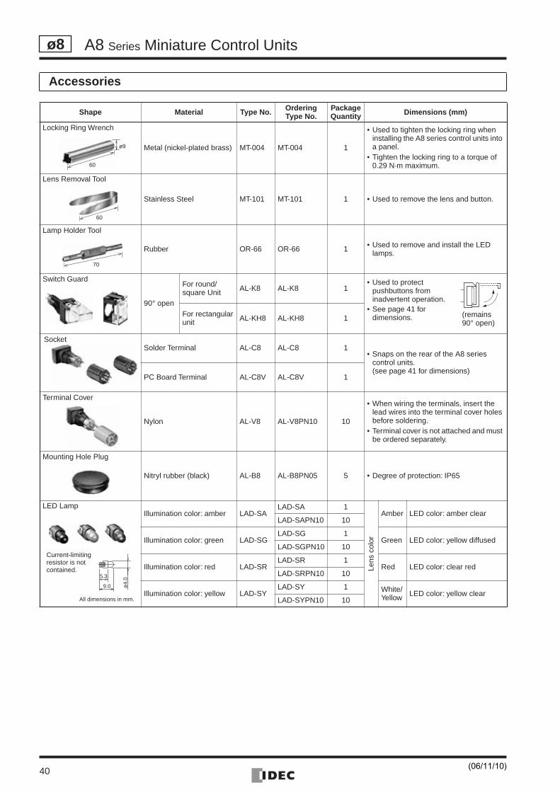
Accessories
Shape Material Type No. OrderingType No.
PackageQuantity Dimensions (mm)
Locking Ring Wrench
Metal (nickel-plated brass) MT-004 MT-004 1
• Used to tighten the locking ring when installing the A8 series control units into a panel.
• Tighten the locking ring to a torque of 0.29 N·m maximum.
Lens Removal Tool
Stainless Steel MT-101 MT-101 1 • Used to remove the lens and button.
Lamp Holder Tool
Rubber OR-66 OR-66 1 • Used to remove and install the LED lamps.
Switch Guard
90° open
For round/square Unit AL-K8 AL-K8 1
• Used to protect pushbuttons from inadvertent operation.
• See page 41 for dimensions.For rectangular
unit AL-KH8 AL-KH8 1
Solder Terminal AL-C8 AL-C8 1• Snaps on the rear of the A8 series
control units.(see page 41 for dimensions)
PC Board Terminal AL-C8V AL-C8V 1
Terminal Cover
Nylon AL-V8 AL-V8PN10 10
• When wiring the terminals, insert the lead wires into the terminal cover holes before soldering.
• Terminal cover is not attached and must be ordered separately.
Mounting Hole Plug
Nitryl rubber (black) AL-B8 AL-B8PN05 5 • Degree of protection: IP65
LED LampIllumination color: amber LAD-SA
LAD-SA 1
Lens
col
or
Amber LED color: amber clearLAD-SAPN10 10
Illumination color: green LAD-SGLAD-SG 1
Green LED color: yellow diffusedLAD-SGPN10 10
Illumination color: red LAD-SRLAD-SR 1
Red LED color: clear redLAD-SRPN10 10
Illumination color: yellow LAD-SYLAD-SY 1 White/
Yellow LED color: yellow clearLAD-SYPN10 10
ø9
60
60
70
(remains 90° open)
Socket
5.3
9.0 ø4.
0
Current-limiting resistor is not contained.
All dimensions in mm.
(06/11/10)
A8 Series Miniature Control Units
41
ø8
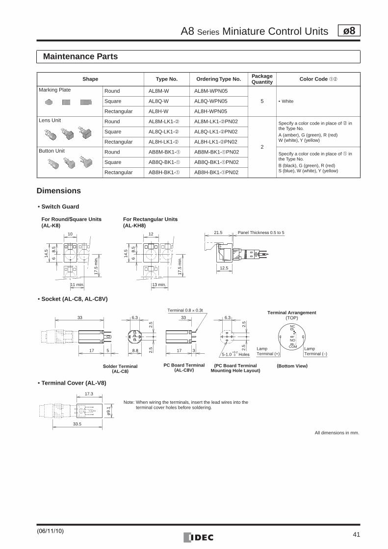
Dimensions
Maintenance Parts
Shape Type No. Ordering Type No. PackageQuantity Color Code ➀➁
Marking Plate Round AL8M-W AL8M-WPN05
5 • WhiteSquare AL8Q-W AL8Q-WPN05
Rectangular AL8H-W AL8H-WPN05
Lens Unit Round AL8M-LK1-➁ AL8M-LK1-➁PN02
2
Specify a color code in place of ➁ in the Type No.A (amber), G (green), R (red)W (white), Y (yellow)
Square AL8Q-LK1-➁ AL8Q-LK1-➁PN02
Rectangular AL8H-LK1-➁ AL8H-LK1-➁PN02
Button Unit Round AB8M-BK1-➀ AB8M-BK1-➀PN02 Specify a color code in place of ➀ in the Type No.B (black), G (green), R (red)S (blue), W (white), Y (yellow)
Square AB8Q-BK1-➀ AB8Q-BK1-➀PN02
Rectangular AB8H-BK1-➀ AB8H-BK1-➀PN02
Panel Thickness 0.5 to 521.5
12.5
10
11 min.
8.5
614.5
17.5
min
.14.5 8.
56
12
13 min.
17.5
min
.
For Round/Square Units(AL-K8)
For Rectangular Units(AL-KH8)
33
Solder Terminal(AL-C8)
17
33
175 3
6.3
8.8
2.5
2.5
6.3
2.5
2.5
Terminal 0.8 × 0.3t
NC
NO
COM LampTerminal (–)
LampTerminal (+)
Terminal Arrangement(TOP)
5-1.0 Holes
PC Board Terminal(AL-C8V)
(PC Board TerminalMounting Hole Layout)
(Bottom View)
+0.20
17.3
33.5
ø9.
1
• Switch Guard
• Socket (AL-C8, AL-C8V)
• Terminal Cover (AL-V8)
Note: When wiring the terminals, insert the lead wires into the terminal cover holes before soldering.
All dimensions in mm.
(06/11/10)
A8 Series Miniature Control Units
42
ø8
Safety Precautions
Operating Instructions
• Turn off the power to A series control units before startinginstallation, removal, wiring, maintenance, and inspection of thecontrol units. Failure to turn power off may cause electrical shocksor fire hazard.
• To avoid burning your hand, use the lamp holder tool whenreplacing lamps.
• For wiring, use wires of a proper size to meet the voltage andcurrent requirements. Failure to tighten terminal screws maycause overheating and create a fire hazard.
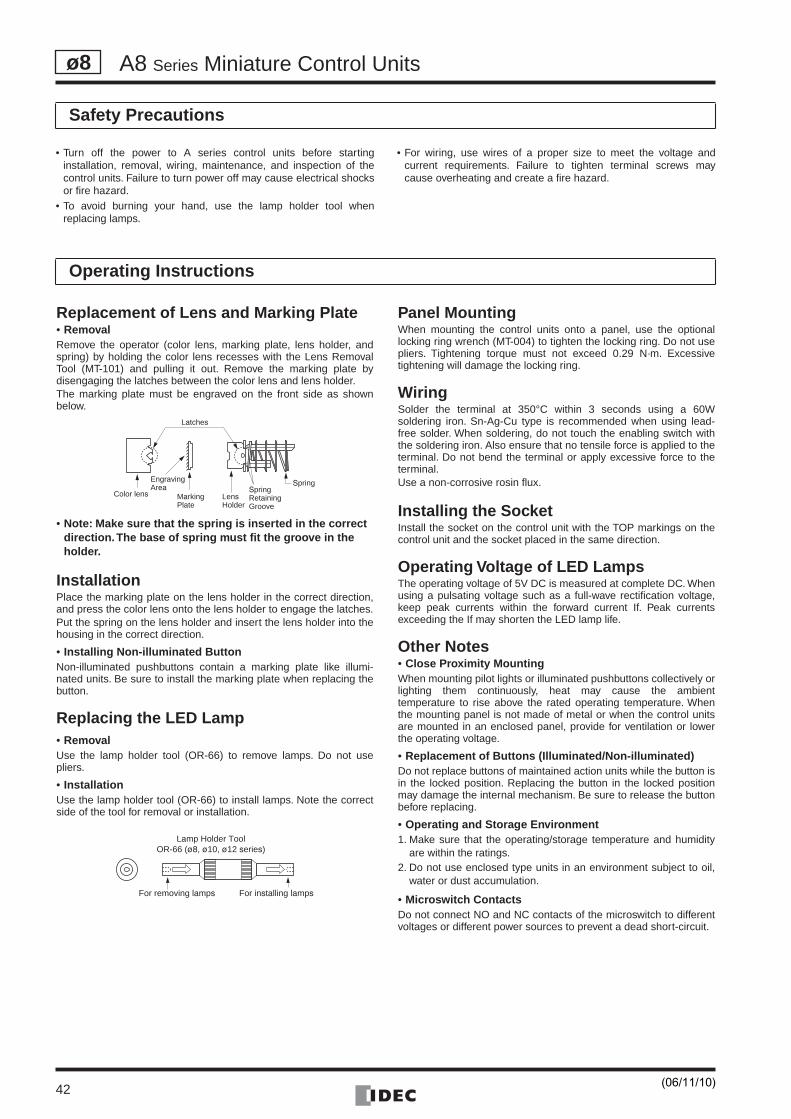
Replacement of Lens and Marking Plate• RemovalRemove the operator (color lens, marking plate, lens holder, andspring) by holding the color lens recesses with the Lens RemovalTool (MT-101) and pulling it out. Remove the marking plate bydisengaging the latches between the color lens and lens holder.The marking plate must be engraved on the front side as shownbelow.
• Note: Make sure that the spring is inserted in the correct direction. The base of spring must fit the groove in the holder.
InstallationPlace the marking plate on the lens holder in the correct direction,and press the color lens onto the lens holder to engage the latches.Put the spring on the lens holder and insert the lens holder into thehousing in the correct direction.
• Installing Non-illuminated ButtonNon-illuminated pushbuttons contain a marking plate like illumi-nated units. Be sure to install the marking plate when replacing thebutton.
Replacing the LED Lamp• RemovalUse the lamp holder tool (OR-66) to remove lamps. Do not usepliers.
• InstallationUse the lamp holder tool (OR-66) to install lamps. Note the correctside of the tool for removal or installation.
Panel MountingWhen mounting the control units onto a panel, use the optionallocking ring wrench (MT-004) to tighten the locking ring. Do not usepliers. Tightening torque must not exceed 0.29 N·m. Excessivetightening will damage the locking ring.
WiringSolder the terminal at 350°C within 3 seconds using a 60Wsoldering iron. Sn-Ag-Cu type is recommended when using lead-free solder. When soldering, do not touch the enabling switch withthe soldering iron. Also ensure that no tensile force is applied to theterminal. Do not bend the terminal or apply excessive force to theterminal.Use a non-corrosive rosin flux.
Installing the SocketInstall the socket on the control unit with the TOP markings on thecontrol unit and the socket placed in the same direction.
Operating Voltage of LED LampsThe operating voltage of 5V DC is measured at complete DC. Whenusing a pulsating voltage such as a full-wave rectification voltage,keep peak currents within the forward current If. Peak currentsexceeding the If may shorten the LED lamp life.
Other Notes• Close Proximity MountingWhen mounting pilot lights or illuminated pushbuttons collectively orlighting them continuously, heat may cause the ambienttemperature to rise above the rated operating temperature. Whenthe mounting panel is not made of metal or when the control unitsare mounted in an enclosed panel, provide for ventilation or lowerthe operating voltage.
• Replacement of Buttons (Illuminated/Non-illuminated)Do not replace buttons of maintained action units while the button isin the locked position. Replacing the button in the locked positionmay damage the internal mechanism. Be sure to release the buttonbefore replacing.
• Operating and Storage Environment1. Make sure that the operating/storage temperature and humidity
are within the ratings.2. Do not use enclosed type units in an environment subject to oil,
water or dust accumulation.
• Microswitch ContactsDo not connect NO and NC contacts of the microswitch to differentvoltages or different power sources to prevent a dead short-circuit.
Latches
Color lens
EngravingArea
MarkingPlate
LensHolder
SpringRetainingGroove
Spring
Lamp Holder ToolOR-66 (ø8, ø10, ø12 series)
For removing lamps For installing lamps
(06/11/10)