119/131r · fifth interim topical report on a study of the mechanics of closed-die forging...
TRANSCRIPT
FIFTH INTERIM TOPICAL REPORT
on
A STUDY OFrTHE MECHANICS OFCLOSED-DIE FORGING
1CALCULATION OF GEOMETRICAL PARAMETERS INDESIGNING THE FORGING PROCESS FOR
AXISYMMETRIC SHAPES
to
ARMY MATERIAL AND MECHANICS RESEARCH CENTER
October 15, 1969
oo&j~ 0 119/131r4b by
T D. E. Nichols, H. J. Henning,and A. M . Sabroff •XO1111O.
Contract DAAG46 -68-C-0 111,, . .
BATTELLE MEMORIAL INSTITUTEColumbus Laboratories
505 King AvenueColumbus, Ohio 43201
011D>&2
FIFTH INTERIM TOPICAL REPORT
on
A STUDY OF THE MECHANICS OFCLOSED-DIE FORGING
CALCULATION OF GEOMETRICAL PARAMETERS INDESIGNING THE FORGING PROCESS FOR
AXISYMMETRIC SHAPES
to
ARMY MATERIAL AND MECHANICS RESEARCH CENTER
October 15, 1969
by
T. Altan, D. E. Nichols, H. J. Henning,and A. M. Sabroff
Contract DAAG46-68-C-0111
BATTELLE MEMORIAL INSTITUTEColumbus Laboratories
505 King AvenueColumbus, Ohio 43201
FOREWORD
This topical report, "Calculation of Geometrical Parameters in Designing theForging Process for Axisymmetric Shapes", covers the analytical work performed underContract No. DAAG46-68-C-0111 by Battelle Memorial Institute, Columbus, Ohio, fromApril 30, 1969, to July 15, 1969.
This work was administered under the technical direction of Mr. Dennis Green ofthe Army Materials and Mechanics Research Center, Watertown, Massachusetts 02172.
This program was carried out under the supervision of Mr. A. M. Sabroff, Chiefof the Metalworking Division, and Mr. H. J. Henning, Associate Chief of the Metal-working Division. Dr. T. Altan, Senior Scientist, is the principal investigator.
BATTELLE MEMORIAL INSTITUTE - COLUMBUS LABORATORIES
FOREWORD
This topical report, "Calculation of Geometrical Parameters in Designing theForging Process for Axisymmetric Shapes", covers the analytical work performed underContract No. DAAG46-68-C-0111 by Battelle Memorial Institute, Columbus, Ohio, fromApril 30, 1969, to July 15, 1969.
This work was administered under the technical direction of Mr. Dennis Green ofthe Army Materials and Mechanics Research Center, Watertown, Massachusetts 02172.
This program was carried out under the supervision of Mr. A. M. Sabroff, Chiefof the Metalworking Division, and Mr. H. J. Henning, Associate Chief of the Metal-working Division. Dr. T. Altan, Senior Scientist, is the principal investigator.
BATTELLE MEMORIAL INSTITUTE -- COLUMBUS LABORATORIES
ABSTRACT
A computer program in FORTRAN language is developed for calculating geometri-cal parameters for axisymmetric forgings. Using the dimensions and the angles givenin the engineering drawing of the forging, the program calculates the forging volume andweight. The shape-difficulty factor may prove useful in process design, for cost esti-mating, and for assisting engineers to make decisions about feasibility and difficulty inmanufacturing. Empirical equations suggested by German and Soviet workers are usedfor calculating the flash dimensions and the flash weight. The computer program isapplied to various forgings, and theoretical results are found to agree with actual experi-mental data. The developed computer program is now available to interested forgingcompanies. It could be used for a systematic analysis of existing forging data, formaking cost estimates after incorporating in-house cost factors, or for designing axi-symmetric forgings with minimum additional effort.
BATTELLE MEMORIAL INSTITUTE -COLUMBUS LABORATORIES
TABLE OF CONTENTS
Page
INTRODUCTION. ....... . . .......................... 1
BASIC VOLUME COMPONENTS OF AN AXISYMMETRIC FORGING . . . . 2
Cylinder ......................... ... . 2Truncated Cone..................... 5Truncated Cone With Fillet................. 6Truncated Cone With Corner............... . . 9
CALCULATION OF GEOMETRICAL QUANTITIES FOR THE ENTIRE FORGING. 11
Perimeter of the Axial Cross-Sectional Surface. ...... . .. ..Surface Area of the Axial Cross-Sectional Surface .............. 13Volume of the Forging.............. . . . .... 13Radius of Center of Gravity of the Half Cross Section. ... . . . .. 14
COMPUTER PROGRAM TO CALCULATE DESIGN VARIABLES FORAXISYMMETRIC FORGINGS ................ ..... ........ 14
Program Input . . .................................... 15Program Calculations and Output.. . ...................... 16
APPLICATION TO PRACTICAL FORGINGS ........................ 18
DISCUSSION.. ........ . .......................... 24
REFERENCES . .......................................... 24
APPENDIX A
THE SHAPE-DIFFICULTY FACTOR FOR AXISYMMETRIC FORGINGS . A-1
APPENDIX B
EMPIRICAL FORMULAS FOR PREDICTING FLASH DIMENSIONS ANDFLASH WEIGHT...................... B-1
APPENDIX C
SYMBOLS USED IN THE FORTRAN PROGRAM ...................... C-1
APPENDIX D
FORTRAN COMPUTER PROGRAM FOR CALCULATING DESIGN PARAMETERSIN AXISYMMETRIC FORGINGS ................................ D-1
BATTELLE MEMORIAL INSTITUTE- COLUMBUS LABORATORIES
CALCULATION OF GEOMETRICAL PARAMETERS INDESIGNING THE FORGING PROCESS FOR
AXISYMMETRIC SHAPES
by
T. Altan, D. E. Nichols, H. J. Henning,and A. M. Sabroff
INTRODUCTION
The design of a forging process involves the calculation or the prediction of
(1) Forging volume and weight(2) Number of blocker shapes to be used, if any(3) Flash geometry, flash width, and flash thickness(4) Flash weight and scale losses(5) Total forging weight, including scale and flash losses.
The second interim topical report, "Methods for Estimating Flash-Gap Dimensions,and Flash Weight in Closed-Die Steel Forging", described a shape-difficulty factor foraxisymmetric forgings first introduced by Soviet workers. (1)* At this time, this factorincludes only the geometrical shape of the forging but excludes the effect of forging ma-terial, die wear, and forging tolerances. The shape-difficulty factor appears to be use-ful in predicting the difficulty involved in forging a part and in calculating the, flash di-
mensions and flash weight by using statistically derived empirical formulas. Theseformulas and the derivation of the shape-difficulty factor were given in the second topicalreport, and they are summarized in Appendix A. In the present work, the derivationand practical use of a FORTRAN computer program is described. This program calcu-lates, from the dimensions given in the engineering drawing of a particular forging, thefollowing variables:
(1) Volume of actual forging, excluding flash and scale losses(2) Shape-difficulty factor(3) Flash width and flash thickness(4) Weight of the flash and scale losses(5) Total forging weight, including scale and flash losses(6) Plane area of forging, including flash.
The computer program is written for axisymmetric steel forgings forged from a cylin-
drical billet. However, it can be extended easily to analyze intermediate blocker forg-ings necessary for forging complicated axisymmetric shapes. Practical shop experiencewill be necessary to develop the shape-difficulty factor into a characteristic quantity
that indicates, for a given material, the number of necessary blocking operations andthe fabrication cost associated with a specific forging shape.
*References to work described in three papers by Russian authors have been discussed in the second interim report.
BATTELLE MEMORIAL INSTITUTE- COLUMBUS LABORATORIES
2
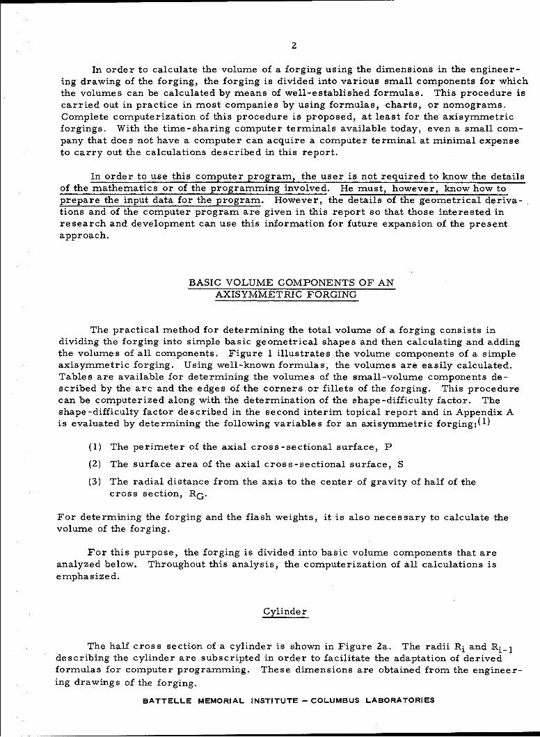
In order to calculate the volume of a forging using the dimensions in the engineer-ing drawing of the forging, the forging is divided into various small components for whichthe volumes can be calculated by means of well-established formulas. This procedure iscarried out in practice in most companies by using formulas, charts, or nomograms.Complete computerization of this procedure is proposed, at least for the axisymmetricforgings. With the time-sharing computer terminals available today, even a small com-pany that does not have a computer can acquire a computer terminal at minimal expenseto carry out the calculations described in this report.
In order to use this computer program, the user is not required to know the detailsof the mathematics or of the programming involved. He must, however, know how toprepare the input data for the program. However, the details of the geometrical deriva-tions and of the computer program are given in this report so that those interested inresearch and development can use this information for future expansion of the presentapproach.
BASIC VOLUME COMPONENTS OF ANAXISYMMETRIC FORGING
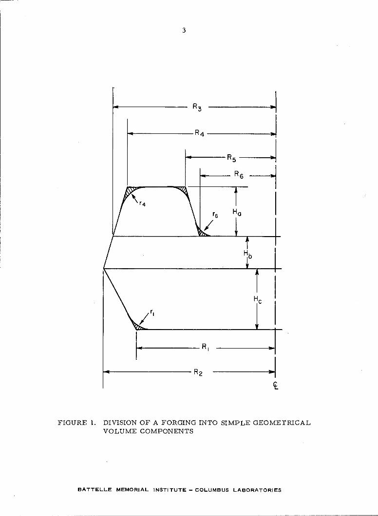
The practical method for determining the total volume of a forging consists individing the forging into simple basic geometrical shapes and then calculating and addingthe volumes of all components. Figure I illustrates the volume components of a simpleaxisymmetric forging. Using well-known formulas, the volumes are easily calculated.Tables are available for determining the volumes of the small-volume components de-scribed by the arc and the edges of the corners or fillets of the forging. This procedurecan be computerized along with the determination of the shape-difficulty factor. Theshape-difficulty factor described in the second interim topical report and in Appendix Ais evaluated by determining the following variables for an axisymmetric forging:(I)
(1) The perimeter of the axial cross-sectional surface, P
(2) The surface area of the axial cross-sectional surface, S
(3) The radial distance from the axis to the center of gravity of half of thecross section, RG.
For determining the forging and the flash weights, it is also necessary to calculate thevolume of the forging.
For this purpose, the forging is divided into basic volume components that areanalyzed below. Throughout this analysis, the computerization of all calculations isemphasized.
Cylinder
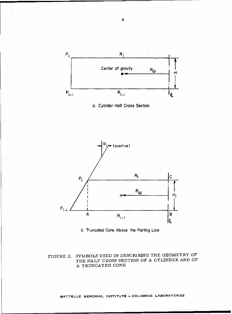
The half cross section of a cylinder is shown in Figure 2a. The radii Ri and Ri_1describing the cylinder are subscripted in order to facilitate the adaptation of derivedformulas for computer programming. These dimensions are obtained from the engineer-ing drawings of the forging.
BATTELLE MEMORIAL INSTITUTE- COLUMBUS LABORATORIES
3
_ R4
i• R5
< R6
/7r4a
r 6 H0
RII
FIGURE 1. DIVISION OF A FORGING INTO SIMPLE GEOMETRICALVOLUME COMPONENTS
BATTELLE MEMORIAL INSTITUTE- COLUMBUS LABORATORIES
4
P1 R1
Center of gravity R
Pi-I RI-,I H
a. Cylinder Half Cross Section
a1 (positive)
PP Ri C
Pi- IA Ri-I B
b. Truncated Cone Above the Parting Line
FIGURE Z. SYMBOLS USED IN DESCRIBING THE GEOMETRY OF
THE HALF CROSS SECTION OF A CYLINDER AND OF
A TRUNCATED CONE
BATTELLE MEMORIAL INSTITUTE- COLUMBUS LABORATORIES
5
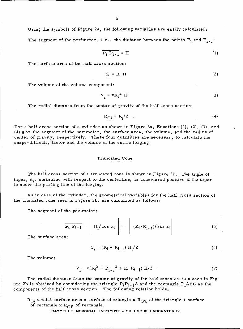
Using the symbols of Figure 2a, the following variables are easily calculated:
The segment of the perimeter, i.e., the distance between the points Pi and Pi-l1:
Pi Ni-i = H (1)
The surface area of the half cross section:
Si = Ri H (2)
The volume of the volume component:
Vi = ?TRi2 H (3)
The radial distance from the center of gravity of the half cross section:
RGi = Ri/2 (4)
For a half cross section of a cylinder as shown in Figure 2a, Equations (1), (2), (3), and(4) give the segment of the perimeter, the surface area, the volume, and the radius ofcenter of gravity, respectively. These four quantities are necessary to calculate theshape-difficulty factor and the volume of the entire forging.
Truncated Cone
The half cross section of a truncated cone is shown in Figure 2b. The angle oftaper, ci, measured with respect to the centerline, is considered positive if the taperis above the parting line of the forging.
As in case of the cylinder, the geometrical variables for the half cross section ofthe truncated cone seen in Figure 2b, are calculated as follows:
The segment of the perimeter:
Pi Pi-l Hj/cos aji (Pi-Ri-l)/sin aix (5)
The surface area:
Si = (Ri + Ri_1) Hi/2 (6)
The volume:
V 7T(Ri2 + R 2 + RR /3.(7)Si ii) H/31(-)
The radial distance from the center of gravity of the half cross section seen in Fig-ure 2b is obtained by considering the triangle PiPi_lA and the rectangle PiABC as thecomponents of the half cross section. The following relation holds:
RGi x total surface area = surface of triangle x RGT of the triangle + surfaceof rectangle x RGR of rectangle,
BATTELLE MEMORIAL INSTITUTE- COLUMBUS LABORATORIES
6
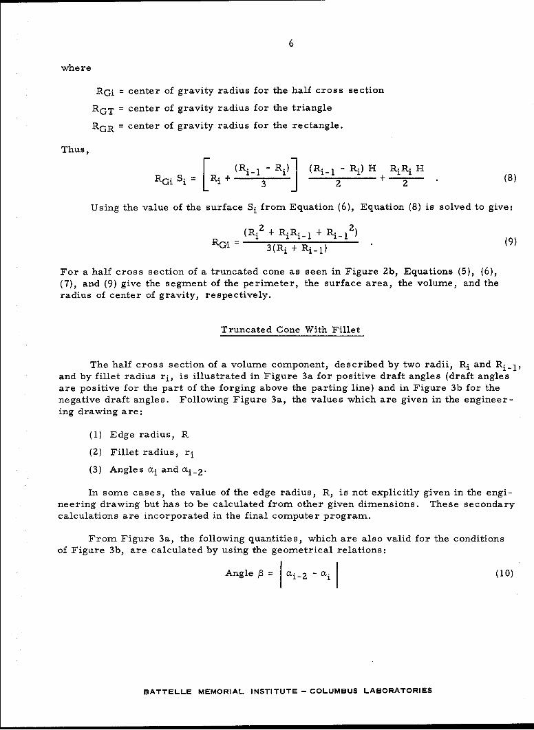
whe re
RGi = center of gravity radius for the half cross section
RGT = center of gravity radius for the triangle
RGR = center of gravity radius for the rectangle.
Thus,
i (Ri_1 - Ri)] (Ri_ 1 - Ri) H RiRi HRG Si = Ri + 3 J 2 + 2 (8)
Using the value of the surface Si from Equation (6), Equation (8) is solved to give:
(Ri2 + RiRi-i + Ri-12RGi - 3(Ri + Ri-l)
For a half cross section of a truncated cone as seen in Figure 2b, Equations (5), (6),(7), and (9) give the segment of the perimeter, the surface area, the volume, and theradius of center of gravity, respectively.
Truncated Cone With Fillet
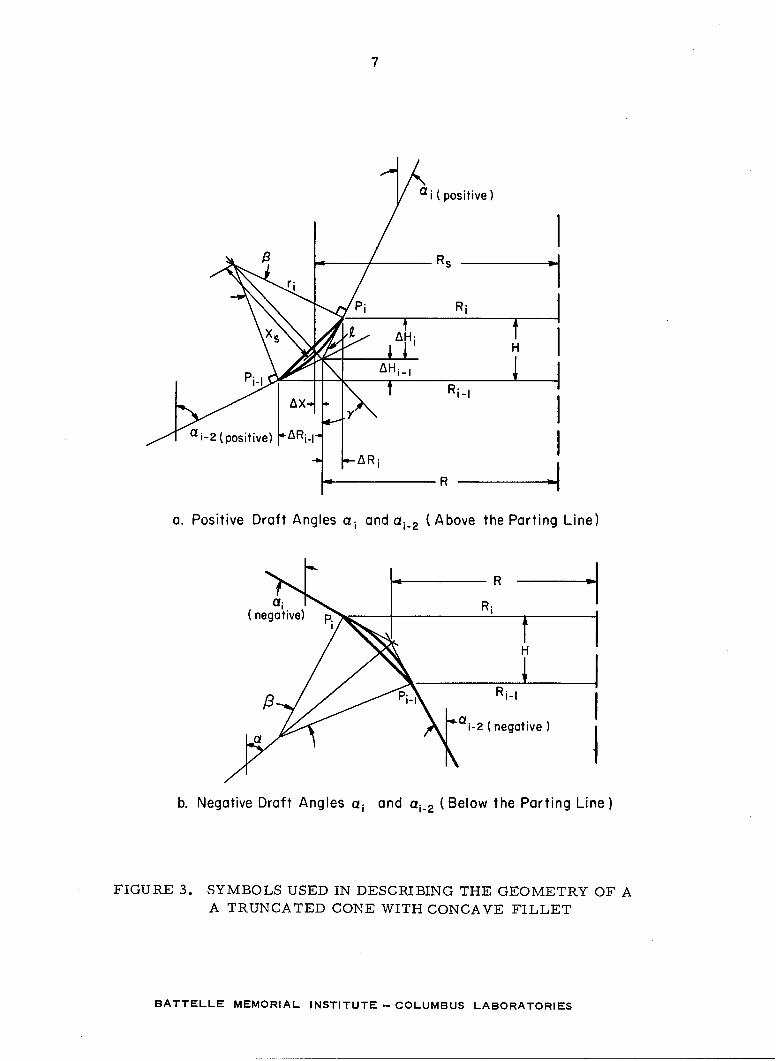
The half cross section of a volume component, described by two radii, Ri and Ri-1,and by fillet radius ri, is illustrated in Figure 3a for positive draft angles (draft anglesare positive for the part of the forging above the parting line) and in Figure 3b for thenegative draft angles. Following Figure 3a, the values which are given in the engineer-ing drawing are:
(1) Edge radius, R
(2) Fillet radius, ri
(3) Angles cmi and 0i_2.
In some cases, the value of the edge radius, R, is not explicitly given in the engi-neering drawing but has to be calculated from other given dimensions. These secondarycalculations are incorporated in the final computer program.
From Figure 3a, the following quantities, which are also valid for the conditionsof Figure 3b, are calculated by using the geometrical relations:
Angle = i2 - ori f (10)
BATTELLE MEMORIAL INSTITUTE -COLUMBUS LABORATORIES
7
a i ( positive)
a1i2 (positive) ~RiI
a. Positive Draft Angles ai and ai.2 (Above the Parting Line)
le Rs
(negative) p
rii ______. Ri-I
2 ( negative) Ib. Negative Draft Angles ai and ai_2 (Below the Parting Line)
FIGURE 3. SYMBOLS USED IN DESCRIBING THE GEOMETRY OF AA TRUNCATED CONE WITH CONCAVE FILLET
BATTELLE MEMORIAL INSTITUTE -- COLUMBUS LABORATORIES
8
and, using
£= ri tan (/3/2) (11)
AKi = £ sin mi (12)
AHi = 2 cos ai (13)
ARi_1 = sin 0i-2 (14)
AzHi_1 = cos ai-2 (15)
Using Equation (12), the radius for the point Pi is
Ri = R - ARi . (16)
Using Equation (14), the radius for the point Pi-I is
Ri1--I =R + Ai_1 (17)
The height, H, of the volume component considered is
H = AHi + AHi_1 , (18)
where Hi and Hi_1 are given by Equations (13) and (15), respectively.
The surface area of the circular segment defined by the straight line PiPi_ I and bythe arc PiPi-l is
r 2A =--(13 - sin l3) ,(19)
where the angle, /3, is given by Equation (10).
The distance between the center of the arc and the center of gravity of the circularsegment is
2r.3~ sin3 /3/2
3 AXs= A (20)
The distance, Ax, as seen in Figure 3a, is
Ax = x( sin (21)
whe re
angle y = /3/2 + 7 - _2 for ai_2 > 0 (Figure 2a) (22a)
P= -/3/2- ai_2 for ci_2 < 0 (Figure 2b) (22b)
BATTELLE MEMORIAL INSTITUTE- COLUMBUS LABORATORIES
9
The radius for the center of gravity of the circular segment defined by the arcPiPiI and by the line PiPi_l is given by
Rs = R + Ax (23)
The quantities given by Equations (10) through (23) are calculated by using only the valuesof the edge radii R, fillet radii ri and of the angles ci and ai-2, all of which are given inengineering drawings.
Now, the important geometrical variables for the volume component under consid-eration can be calculated:
The segment of perimeter, arc PiPi = 3 ri (24)
(Ri + Ri-1) HThe surface area, Si = 2 - A (25)
The volume, Vi = 'T(Ri 2 + Ri_ 2 + RiRiI)H/3 - 2'RsA (26)
The radius of the center of gravity, obtained from RGi = (RGcSC - A Rs)/Si . (27)
In Equation (27), the radius RGC is the radius of the center of gravity of the half-truncated cone described by Pi and Pi-l" RGC is calculated by applying Equation (9).SC is the surface area of the same half cross section of the truncated cone and is calcu-lated with Equation (6). All other quantities used in Equations (24) through (27) are cal-culated by using one or more of Equations (10) through (23).
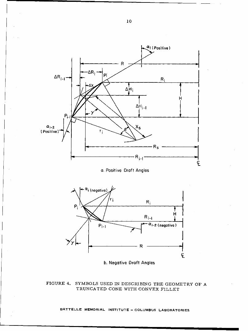
Truncated Cone With Corner
The half cross section of a volume component with a corner is shown in Figure 4 afor positive draft angles and in Figure 4b for negative draft angles. Again, the edgeradius, R, the corner radius, ri, and the angles ai and ai_2 are given in the engineeringdrawing of the forging.
Equations (10) through (21) are still valid for calculating various geometrical quan-tities shown in Figure 4a.
The angle -y is given by
- - - /3/2 - ai_2 for ai_ 2 > 0 (Figure 3a) (2 8a)
' = f- I 0i-2 + /3/2 for ai_2 < 0 (Figure 3b) (28b)
The radius for the center of gravity of the circular segment is given by
Rs = R - Ax . (29)
BATTELLE MEMORIAL INSTITUTE- COLUMBUS LABORATORIES
10
AR.C1
a1 i -.. ..2 '
a. Positive Draft Angles
RiIR
R Pi-I -2(ngtv )
i~
b. Negative Draft Angles
FIGURE 4. SYMBOLS USED IN DESCRIBING THE GEOMETRY OF ATRUNCATED GONE WITH CONVEX FILLET
BATTELLE MEMORIAL INSTITUTE- COLUMBUS LABORATORIES
'~~~~~ ~~~ S R S
11
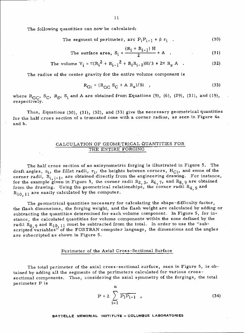
The following quantities can now be calculated:
The segment of perimeter, arc PiPi-l = /3 ri (30)
(Ri + Ri-l.) H
The surface area, Si = 2 +A (31)
The volume Vi = 7T(Riz + Ri- 12 + RiRiI)H/3 + 27f Rs A (32)
The radius of the center gravity for the entire volume component is
RGi = (RGC SC + A Rs)/Si , (33)
where RGC, SC, RS, Si and A are obtained from Equations (9), (6), (29), (31), and (19),
respectively.
Thus, Equations (30), (31), (32), and (33) give the necessary geometrical quantities
for the half cross section of a truncated cone with a corner radius, as seen in Figure 4a
and b.
CALCULATION OF GEOMETRICAL QUANTITIES FORTHE ENTIRE FORGING
The half cross section of an axisymmetric forging is illustrated in Figure 5. The
draft angles, ai, the fillet radii, ri, the heights between corners, HCi, and some of the
corner radii, Ri, i-1, are obtained directly from the engineering drawing. For instance,
for the example given in Figure 5, the corner radii R 2 3, R 6 , 7, and R 8 , 9 are obtained
from the drawing. Using the geometrical relationships, the corner radii R 4 5 and
RI0, I Iare easily calculated by the computer.
The geometrical quantities necessary for calculating the shape-difficulty factor,
the flash dimensions, the forging weight, and the flash weight are calculated by adding or
subtracting the quantities determined for each volume component. In Figure 5, for in-
stance, the calculated quantities for volume components within the zone defined by the
radii R 8 9 and RI 0 11 must be subtracted from the total. In order to use the "sub-
scripted variables" of the FORTRAN computer language, the dimensions and the angles
are subscripted as shown in Figure 5.
Perimeter of the Axial Cross-Sectional Surface
The total perimeter of the axial cross-sectional surface, seen in Figure 5, is ob-
tained by adding all the segments of the perimeters calculated for various cross-
sectional components. Thus, considering the axial symmetry of the forgings, the total
perimeter P isn
P = 2 PiPil 1 (34)
i=l
BATTELLE MEMORIAL INSTITUTE - COLUMBUS LABORATORIES
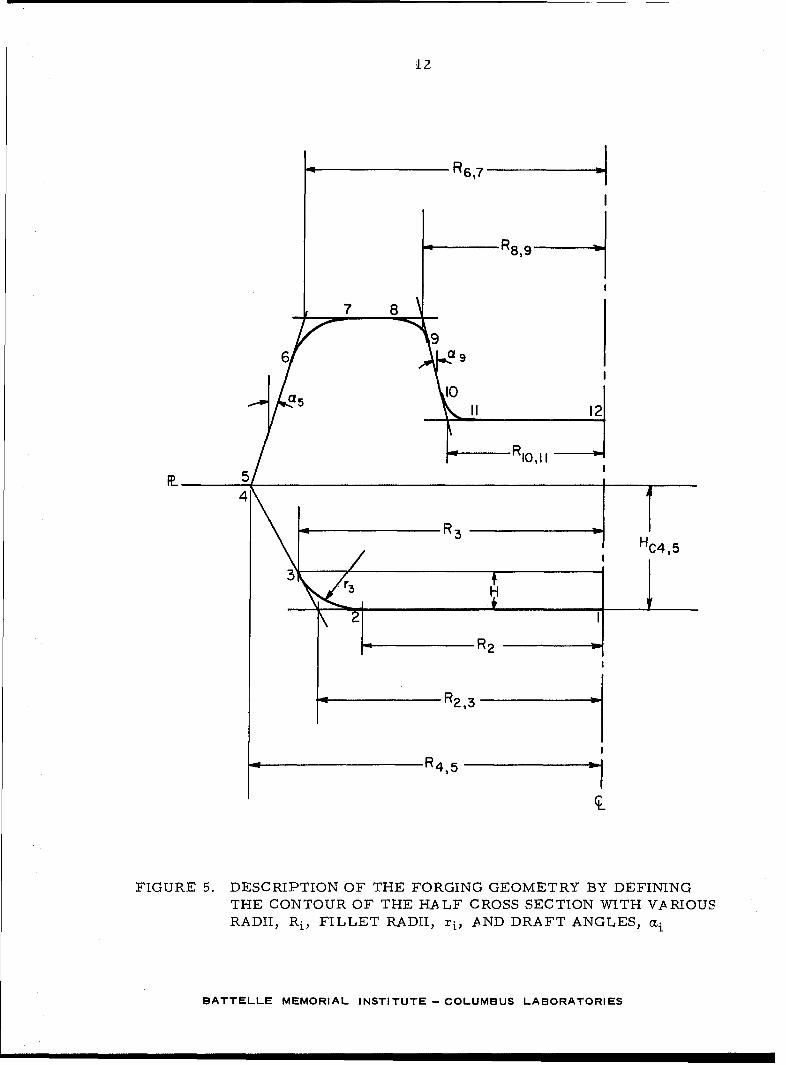
12
"R6 17
R8 ,9
7 8 _
96 a 9
a 5 o5 a 5 12
I 5/
R3 HC4 5
2R2
R2 ,3
R 4 15
FIGURE 5. DESCRIPTION OF THE FORGING GEOMETRY BY DEFININGTHE CONTOUR OF THE HALF CROSS SECTION WITH VARIOUSRADII, Ri, FILLET RADII, ri, AND DRAFT ANGLES, ai
BATTELLE MEMORIAL INSTITUTE- COLUMBUS LABORATORIES
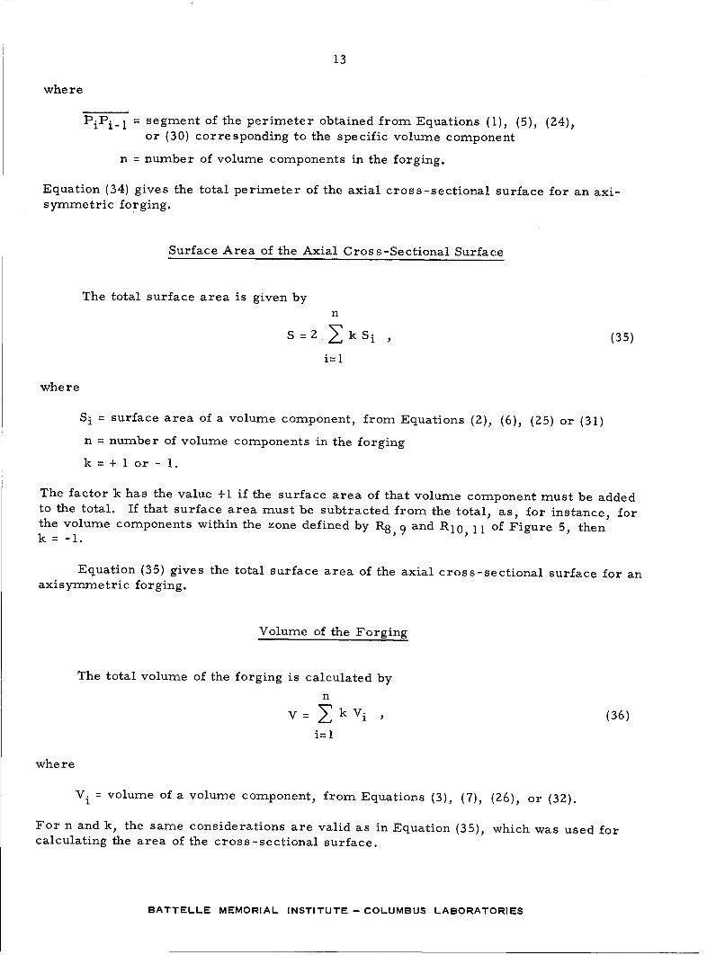
13
where
PiPi-l = segment of the perimeter obtained from Equations (1), (5), (24),or (30) corresponding to the specific volume component
n = number of volume components in the forging.
Equation (34) gives the total perimeter of the axial cross-sectional surface for an axi-symmetric forging.
Surface Area of the Axial Cross-Sectional Surface
The total surface area is given byn
S=2 ZkSi (35)
i=l
where
Si = surface area of a volume component, from Equations (2), (6), (25) or (31)
n = number of volume components in the forging
k = + 1 or - 1.
The factor k has the value +1 if the surface area of that volume component must be addedto the total. If that surface area must be subtracted from the total, as, for instance, forthe volume components within the zone defined by R 8 , 9 and RIO, 11 of Figure 5, thenk= -1.
Equation (35) gives the total surface area of the axial cross-sectional surface for anaxisymmetric forging.
Volume of the Forging
The total volume of the forging is calculated by
n
V = k Vi , (36)i=1
where
V. = volume of a volume component, from Equations (3), (7), (26), or (32).
For n and k, the same considerations are valid as in Equation (35), which was used forcalculating the area of the cross-sectional surface.
BATTELLE MEMORIAL INSTITUTE-COLUMBUS LABORATORIES
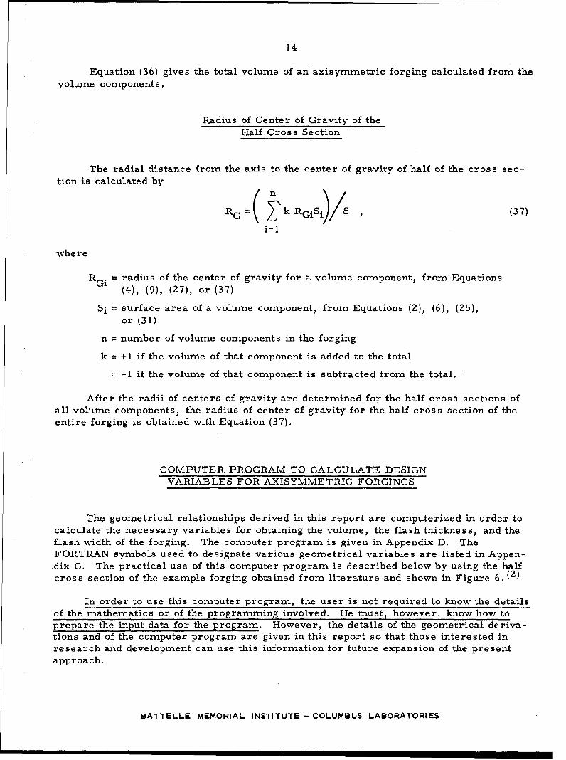
14
Equation (36) gives the total volume of an axisymmetric forging calculated from thevolume components.
Radius of Center of Gravity of theHalf Cross Section
The radial distance from the axis to the center of gravity of half of the cross sec-tion is calculated by
RG= k RGiS)/S , (37)
i--1
where
RGi = radius of the center of gravity for a volume component, from Equations(4), (9), (27), or (37)
Si = surface area of a volume component, from Equations (2), (6), (25),or (31)
n = number of volume components in the forging
k = +1 if the volume of that component is added to the total
= -1 if the volume of that component is subtracted from the total.
After the radii of centers of gravity are determined for the half cross sections ofall volume components, the radius of center of gravity for the half cross section of theentire forging is obtained with Equation (37).
COMPUTER PROGRAM TO CALCULATE DESIGNVARIABLES FOR AXISYMMETRIC FORGINGS
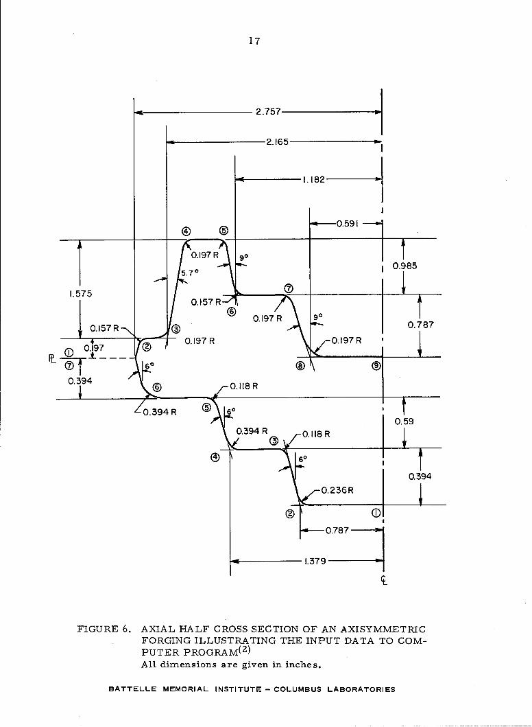
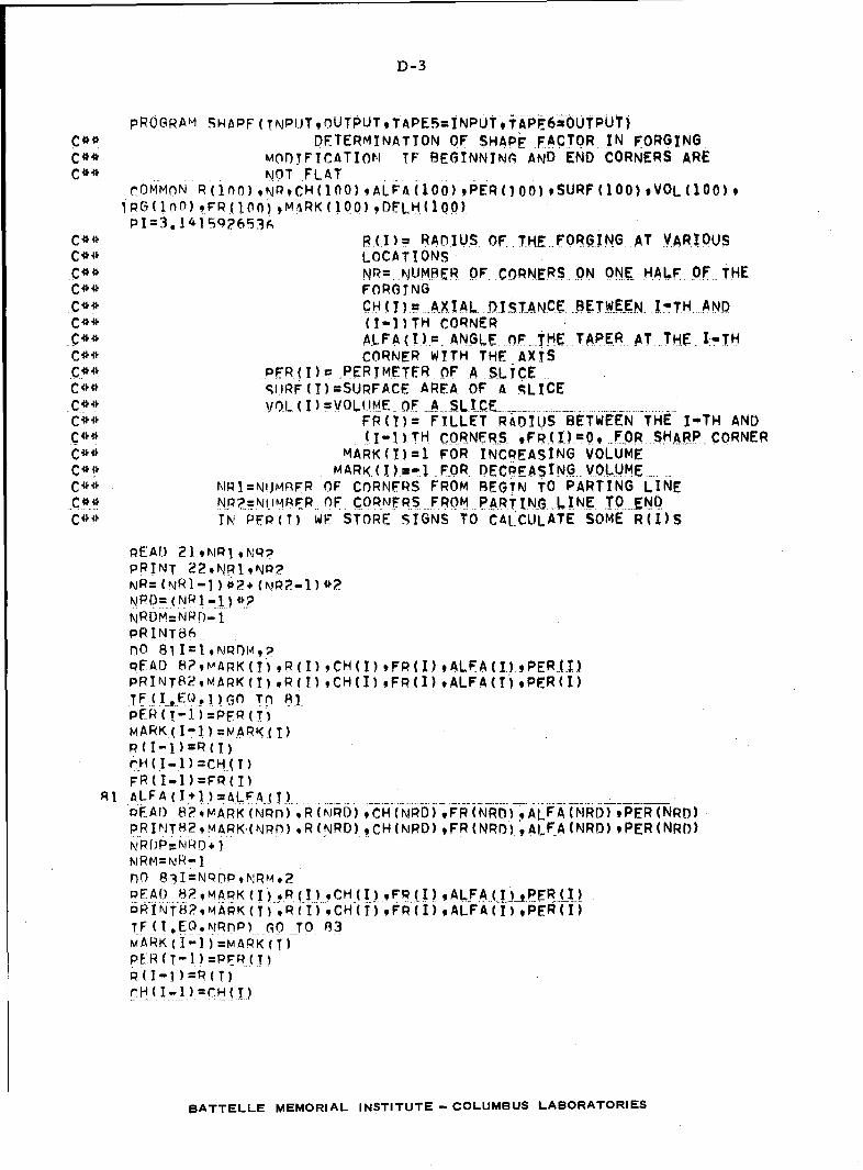
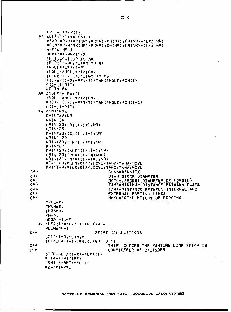
The geometrical relationships derived in this report are computerized in order tocalculate the necessary variables for obtaining the volume, the flash thickness, and theflash width of the forging. The computer program is given in Appendix D. TheFORTRAN symbols used to designate various geometrical variables are listed in Appen-dix C. The practical use of this computer program is described below by using the halfcross section of the example forging obtained from literature and shown in Figure 6. (2)
In order to use this computer program, the user is not required to know the detailsof the mathematics or of the programming involved. He must, however, know how toprepare the input data for the program. However, the details of the geometrical deriva-tions and of the computer program are given in this report so that those interested inresearch and development can use this information for future expansion of the presentapproach.
BATTELLE MEMORIAL INSTITUTE - COLUMBUS LABORATORIES
15
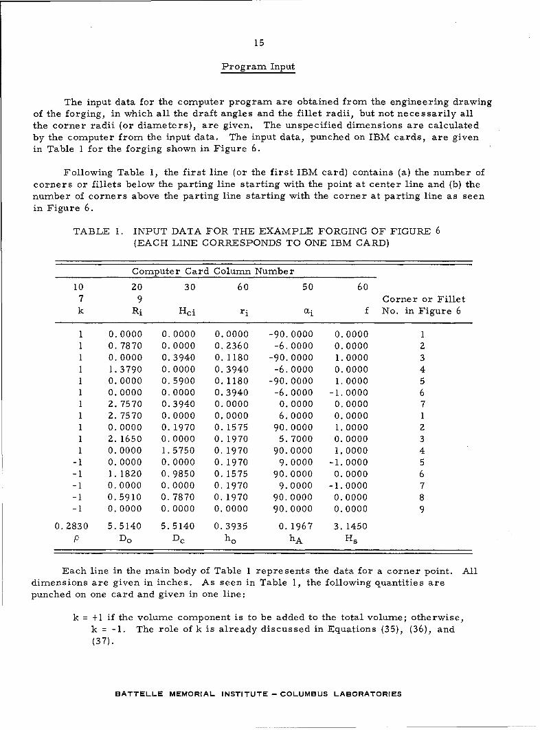
Program Input
The input data for the computer program are obtained from the engineering drawingof the forging, in which all the draft angles and the fillet radii, but not necessarily allthe corner radii (or diameters), are given. The unspecified dimensions are calculatedby the computer from the input data. The input data, punched on IBM cards, are givenin Table 1 for the forging shown in Figure 6.
Following Table 1, the first line (or the first IBM card) contains (a) the number ofcorners or fillets below the parting line starting with the point at center line and (b) thenumber of corners above the parting line starting with the corner at parting line as seenin Figure 6.
TABLE 1. INPUT DATA FOR THE EXAMPLE FORGING OF FIGURE 6(EACH LINE CORRESPONDS TO ONE IBM CARD)
Computer Card Column Number
10 20 30 60 50 607 9 Corner or Filletk Ri Hci ri 0i f No. in Figure 6
1 0.0000 0.0000 0.0000 -90.0000 0.0000 11 0.7870 0.0000 0.2360 -6.0000 0.0000 21 0.0000 0.3940 0. 1180 -90. 0000 1.0000 31 1.3790 0.0000 0.3940 -6.0000 0.0000 41 0.0000 0.5900 0.1180 -90.0000 1.0000 51 0.0000 0.0000 0.3940 -6.0000 -1.0000 61 2.7570 0.3940 0.0000 0.0000 0.0000 71 2. 7570 0.0000 0.0000 6.0000 0.0000 11 0.0000 0. 1970 0. 1575 90.0000 1.0000 21 2. 1650 0.0000 0. 1970 5. 7000 0.0000 31 0.0000 1.5750 0. 1970 90.0000 1.0000 4
-1 0.0000 0.0000 0. 1970 9.0000 -1.0000 5-1 1. 1820 0.9850 0. 1575 90.0000 0.0000 6-1 0.0000 0.0000 0. 1970 9.0000 -1.0000 7-1 0.5910 0.7870 0. 1970 90.0000 0.0000 8-1 0. 0000 0.0000 0.0000 90.0000 0.0000 9
0.2830 5.5140 5.5140 0.3935 0. 1967 3. 1450P Do Dc ho hA Hs
Each line in the main body of Table 1 represents the data for a corner point. Alldimensions are given in inches. As seen in Table 1, the following quantities arepunched on one card and given in one line:
k = +1 if the volume component is to be added to the total volume; otherwise,k = -1. The role of k is already discussed in Equations (35), (36), and(37).
BATTELLE MEMORIAL INSTITUTE - COLUMBUS LABORATORIES
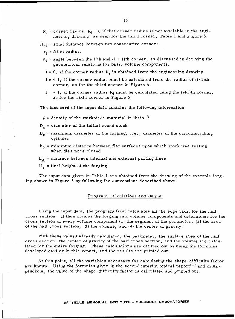
16
Ri = corner radius; Ri = 0 if that corner radius is not available in the engi-neering drawing, as seen for the third corner, Table 1 and Figure 6.
Hci = axial distance between two consecutive corners.
ri = fillet radius.
(Xi = angle between the i'th and (i + 1)th corner, as discussed in deriving thegeometrical relations for basic volume components.
f = 0, if the corner radius Ri is obtained from the engineering drawing.
f = + 1, if the corner radius must be calculated from the radius of (i-1)thcorner, as for the third corner in Figure 6.
f = - 1, if the corner radius Ri must be calculated using the (i+l)th corner,as for the sixth corner in Figure 6.
The last card of the input data contains the following information:
p = density of the workpiece material in lb/in. 3
Do = diameter of the initial round stock
Dc = maximum diameter of the forging, i. e. , diameter of the circumscribingcylinder
ho = minimum distance between flat surfaces upon which stock was restingwhen dies were closed
hA = distance between internal and external parting lines
Hs = final height of the forging.
The input data given in Table 1 are obtained from the drawing of the example forg-ing shown in Figure 6 by following the conventions described above.
Program Calculations and Output
Using the input data, the program first calculates all the edge radii for the halfcross section. It then divides the forging into volume components and determines for thecross section of every volume component (1) the segment of the perimeter, (2) the areaof the half cross section, (3) the volume, and (4) the center of gravity.
With these values already calculated, the perimeter, the surface area of the halfcross section, the center of gravity of the half cross section, and the volume are calcu-lated for the entire forging. These calculations are carried out by using the formulasdeveloped earlier in this report, and the results are printed out.
At this point, all the variables necessary for calculating the shape-difficulty factorare known. Using the formulas given in the second interim topical report(1 ) and in Ap-pendix A, the value of the shape-difficulty factor is calculated and printed out.
BATTELLE MEMORIAL INSTITUTE - COLUMBUS LABORATORIES
17
2.757
'- 2.165
1.182 -
0 •0.591
0.O197 R g
5.70 -- 0.985
1,575
0.157R 0.787
0.3940
--O.394R () 0.0.197R 0. 1 97RI 05
0.3940.0359
-0.78 7
1.379-
FIGURE 6. AXIAL HALF CROSS SECTION OF AN AXISYMMETRICFORGING ILLUSTRATING THE INPUT DATA TO COM-PUTER PROGRAM( 2 )
All dimensions are given in inches.
BATTELLE MEMORIAL INSTITUTE- COLUMBUS LABORATORIES
18
The flash thickness is calculated by using the empirical formula suggested by
Wolf. (1) For the computation of the flash ratio, the formula suggested by Wolf is used
if the forging weighs less than I pound. Otherwise, Teterin and Tornovskij's formula
is applied for both in calculating the flash ratio and the flash weight. All these formulas
were discussed in detail in the second interim topical report and are given in Appendix B.
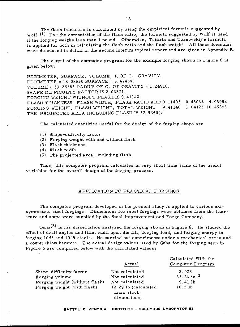
The output of the computer program for the example forging shown in Figure 6 is
given below:
PERIMETER, SURFACE, VOLUME, R OF C. GRAVITY.
PERIMETER = 18. 08550 SURFACE = 8.47459.
VOLUME = 33.25583 RADIUS OF C. OF GRAVITY = 1.24910.
SHAPE DIFFICULTY FACTOR IS 2.02221.
FORGING WEIGHT WITHOUT FLASH IS 9.41140.
FLASH THICKNESS, FLASH WIDTH, FLASH RATIO ARE 0. 11403 0.46062 4.03952.
FORGING WEIGHT, FLASH WEIGHT, TOTAL WEIGHT 9.41140 1.04123 10.45263.
THE PROJECTED AREA INCLUDING FLASH IS 32. 52509.
The calculated quantities useful for the design of the forging shape are
(1) Shape -difficulty factor(2) Forging weight with and without flash
(3) Flash thickness(4) Flash width(5) The projected area, including flash.
Thus, this computer program calculates in very short time some of the usefulvariables for the overall design of the forging process.
APPLICATION TO PRACTICAL FORGINGS
The computer program developed in the present study is applied to various axi-symmetric steel forgings. Dimensions for most forgings were obtained from the liter-
ature and some were supplied by the Steel Improvement and Forge Company.
Guha( 2 ) in his dissertation analyzed the forging shown in Figure 6. He studied the
effect of draft angles and fillet radii upon die fill, forging load, and forging energy in
forging 1043 and 1045 steels. He carried out experiments under a mechanical press and
a counterblow hammer. The actual design values used by Guha for the forging seen in
Figure 6 are compared below with the calculated values:
Calculated With the
Actual Computer Program
Shape-difficulty factor Not calculated 2. 022
Forging volume Not calculated 33. 26 in. 3
Forging weight (without flash) Not calculated 9. 41 lbForging weight (with flash) 12. 29 lb (calculated 10. 5 lb
from stock
dimensions)
BATTELLE MEMORIAL INSTITUTE- COLUMBUS LABORATORIES
19
Calculated With theActual Computer Program
Flash thickness in die 0. 12 in. 0. 114 in.Flash width in die 0. 59 in. 0.46 in.Flash ratio in die 5 4.04
The above comparison clearly shows that the flash dimensions determined by the com-puter program are close to the actual values used in Guha's experiments. The flash and
scale losses used by Guha are about 30 percent of the actual forging weight, while theflash losses predicted by the computer program are 12. 0 percent of the forging weight.
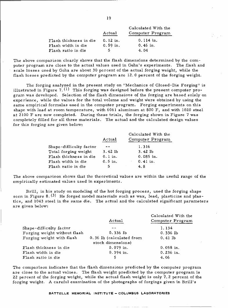
The forging analyzed in the present study on "Mechanics of Closed-Die Forging" isillustrated in Figure 7. (1) This forging was designed before the present computer pro-gram was developed. Selection of the flash dimensions of the forging are based solely on
experience, while the values for the total volume and weight were obtained by using thesame empirical formulas used in the computer program. Forging experiments on thisshape with lead at room temperature, with 6061 aluminum at 800 F, and with 1020 steelat 2100 F are now completed. During these trials, the forging shown in Figure 7 wascompletely filled for all three materials. The actual and the calculated design valuesfor this forging are given below:
Calculated With the
Actual Computer Program
Shape-difficulty factor -- 1.316Total forging weight 3.42 lb 3.42 lbFlash thickness in die 0. 1 in. 0. 085 in.Flash width in die 0.5 in. 0.41 in.Flash ratio in die 5 4.8
The above comparison shows that the theoretical values are within the useful range of theempirically estimated values used in experiments.
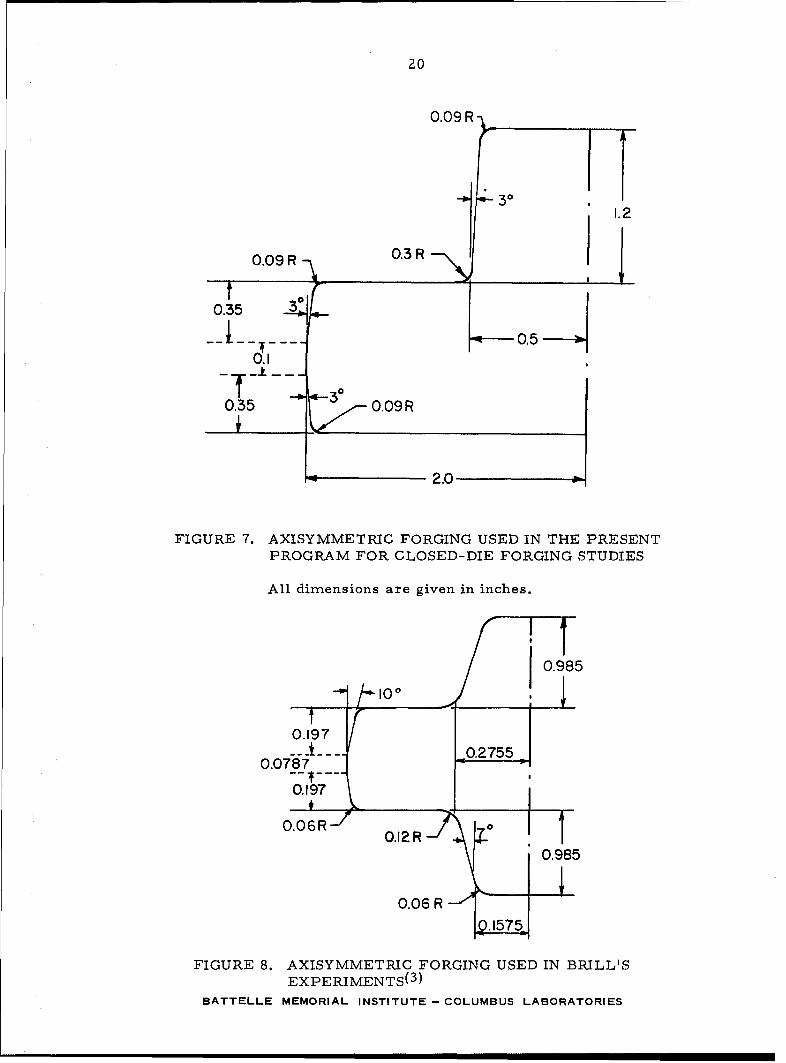
Brill, in his study on modeling of the hot forging process, used the forging shape
seen in Figure 8. (3) He forged model materials such as wax, lead, plasticine and plas-tics, and 1043 steel in the same die. The actual and the calculated significant parametersare given below:
Calculated With theActual Computer Program
Shape -difficulty factor -- 1. 134Forging weight without flash 0. 336 lb 0. 336 lbForging weight with flash 0. 36 lb (calculated from 0. 41 lb
stock dimensions)
Flash thickness in die 0. 079 in. 0. 058 in.Flash width in die 0. 394 in. 0. 236 in.Flash ratio in die 5 4.06
The comparison indicates that the flash dimensions predicted by the computer programare close to the actual values. The flash weight predicted by the computer program is2Z percent of the forging weight, while the actual flash weight is only 7. 2 percent of theforging weight. A careful examination of the photographs of forgings given in Brill's
BATTELLE MEMORIAL INSTITUTE - COLUMBUS LABORATORIES
20
0.09 R
3 01.2
0.09 R 0.3R L
0.35 _3:
0.5
0.35 0.09 R
2.0
FIGURE 7. AXISYMMETRIC FORGING USED IN THE PRESENTPROGRAM FOR CLOSED-DIE FORGING STUDIES
All dimensions are given in inches.
S~0.985
0.197/
--- ___ .... 0.27550.0787-
0.197
0.985
0.06 R
FIGURE 8. AXISYMMETRIC FORGING USED IN BRILL'SEXPERIMENTS(
3 )
BATTELLE MEMORIAL INSTITUTE - COLUMBUS LABORATORIES
21
dissertation indicates, however, that the die cavity was not always completely filled.The top of the spikes on the top and bottom of some forgings do not appear to have theexact contour of the die cavity at the spike. (3) Consequently, the theoretically predictedvalues for flash weight and flash dimensions seem to be more realistic design values thanthe ones used by Brill. (3)
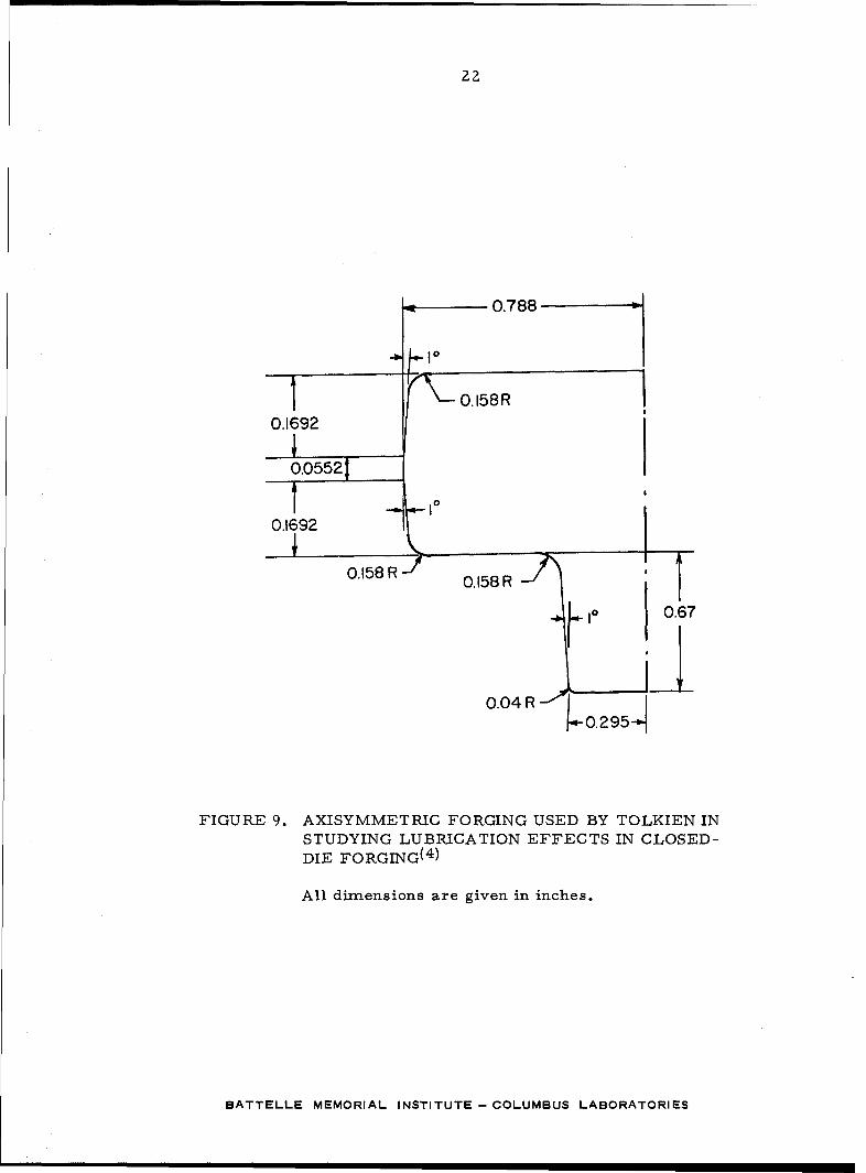
Tolkien made an extensive experimental study on various lubricants in closed-dieforging. (4) He evaluated the friction and the sticking forces of lubricants by using theclosed-die forging seen in Figure 9. The actual and the calculated design parametersfor this forging are given below:
Calculated With theActual Computer Program
Shape -difficulty factor -- 1.014Forging weight without flash 0. 260 lb 0. 260 lbForging weight with flash 0. 336 lb 0. 317 lbFlash thickness in die 0. 0552 in. 0. 0564 in.Flash width in die 0. 138 in. 0.23 in.Flash ratio in die 2.5 4. 1
The agreement between theoretical and actual values is good. The flash thick-nesses are nearly identical, while the theoretical flash width is slightly larger. Theflash weight predicted by computer calculations is less than the actual weight used byTolkien (22 percent versus 29. 2 percent).
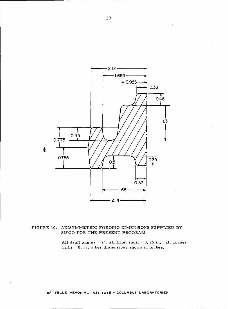
One of the participating companies in this program, Steel Improvement and ForgeCompany, supplied the die and forging drawings for the axisymmetric forging seen inFigure 10. Using the dimensions given in Figure 10, the computer program was used tocalculate the following parameters:
Shape -difficulty factor 1. 8Forging weight without flash 5. 74 lbForging weight with flash 6. 33 lbFlash thickness 0. 100 in.Flash width 0.431 in.Flash ratio 4.35
These values appear to be reasonable for forging the shape seen in Figure 10 fromlow-alloy steel. In SIFCO's actual forging, the material was 347 stainless steel, withone blocker die and one finishing die used. It is interesting to observe that SIFCO's forg-ing (Figure 10) has a shape-difficulty factor of 1. 8, while Guha's forging (Figure 6) has ashape-difficulty factor of 2. 02. Guha could forge his shape without using a blocker diebecause the workpiece material was low-alloy steel. SIFCO's example illustrates thewell-known fact that, in addition to the geometrical shape-difficulty factor, factors de-scribing the influence of forging material, die wear, and forging tolerances must also beconsidered in designing a forging process. Those latter parameters are not included inthe computer program described in this report.
BATTELLE MEMORIAL INSTITUTE- COLUMBUS LABORATORIES
22
0.788
1004
0.1692
0.05521 ..
0.1692
0.158 R 0. 158
0.158 R
0.. 295 I 06
FIGURE 9. AXISYMMETRIC FORGING USED BY TOLKIEN INSTUDYING LUBRICATION EFFECTS IN CLOSED-DIE FORGING(
4 )
All dimensions are given in inches.
BATTELLE MEMORIAL INSTITUTE - COLUMBUS LABORATORIES
23
"2.12"A--1.685
""0.955"-"
0.38
A0.46
0.450.775
0.785 •03
S0.51 03
0.37
1.68
2.14
FIGURE 10. AXISYMMETRIC FORGING DIMENSIONS SUPPLIED BYSIFCO FOR THE PRESENT PROGRAM
All draft angles = 70; all fillet radii = 0. 25 in. ; all cornerradii = 0. 12; other dimensions shown in inches.
BATTELLE MEMORIAL INSTITUTE- COLUMBUS LABORATORIES
24
DISCUSSION
The determination of the number of preforming operations, the design of flash, andthe prediction of flash and scale losses are significant steps in designing a forging pro-cess. The flash geometry has a marked influence upon die loads and stresses and upondie filling. The prediction of flash weight, including scale losses, is a very importantfactor in the overall cost of large-quantity-production forgings. The blocker shapes arenecessary in forging complex shapes of difficult-to-forge materials, and they add toforging costs. It normally takes extensive experience to reasonably estimate these vari-ables and to design the forging process, and they are not included in the current com-puter program. It may be possible to handle such decisions later as experience and dataaccumulate and are introduced into the program.
The difficulty in forging a part depends upon various factors, such as the geomet-rical shape of the forging, the forging material, the forging tolerances, and the expecteddie wear. The "shape-difficulty factor" has been suggested for axisymmetric shapes bySoviet workers. (1) Using the shape-difficulty factor described in Appendix A and statis-tically obtained empirical equations given in Appendix B, it appears to be possible topredict the flash dimensions and the flash weight for axisymmetric low-alloy steel forg-ings. This procedure is extended to calculate the volume of a forging, also, and it isprogrammed for a computer in FORTRAN language. The program uses only informationgiven in the engineering drawing and calculates the total weight of the forging (forgingweight and flash weight). In order to use this computer program, the user is not re-quired to know the details of the mathematics or the programming involved. He mustonly know how to prepare the input data, as shown in Table 1.
The computer program is applied to various forgings, and results have been com-pared with actual experimental data. The agreement between theoretical-empirical pre-dictions and with design data developed experimentally (or suggested by extensive forgingexperience) is very good. The developed computer program is now available to inter-ested forging companies. It could be used for a systematic analysis of existing forgingdata, for making cost estimates after incorporating in-house cost factors, or for design-ing axisnymmetric forgings with a minimum amount of additional effort.
The information presented in this report is not intended to be a ready answer fordesign problems of individual forgers. In order to establish a more exact analysis ofthe forging process, the concept of shape-difficulty factor must be complemented byexperimental-empirical factors describing the effect of forging material, forging toler-ances, and die wear. Every company could find and develop this information to suit itsown needs and operations. The concept of a shape-difficulty factor could be further ex-tended to nonaxisyrmmetric forgings, if there is interest within the industry for this kindof developmental work.
REFERENCES
(1) Altan, T., Henning, H. J., and Sabroff, A. M. , "Methods for Estimating Flash-GapDimensions and Flash Weight in Closed-Die Steel Forging", Second Interim TopicalReport to AMMRC, Watertown, Massachusetts, January 30, 1969.
BATTELLE MEMORIAL INSTITUTE - COLUMBUS LABORATORIES
25 and 26
(2) Guha, S. P. , "Einfluss der Abrundungen an den Werkzeugen beim Gesenkschmiedenauf Kraft-und Arbeitsbedarf sowie den Steigvorgang" (Influence of Fillet Radii onLoad and Energy Requirements and on Die Fill in Closed-Die Forgings). Disserta-tion, Aachen, 1964.
(3) Brill, K. , "Modellwerkstoffe fdr die Massivumformung von Metallen" (Model Mate-rials for Forging of Metals), Dissertation, Hannover, 1963.
(4) Tolkien, H. , "Schmierwirkungen in Schmiedegesenken" (Lubrication Effects in Forg-ing Dies), Dissertation, Hannover, 1961.
BATTELLE MCT3,ORIES
- STU•PTh,
BATTELLE MEMORIAL INSTITUTE -COLUMBUS LABORATORIES
APPENDIX A
THE SHAPE-DIFFICULTY FACTOR FORAXISYMMETRIC FORGINGS
BATTELLE MEMORIAL INSTITUTE - COLUMBUS LABORATORIES
A-1
APPENDIX A
THE SHAPE-DIFFICULTY FACTOR FORAXISYMME TRIC FORGINGS
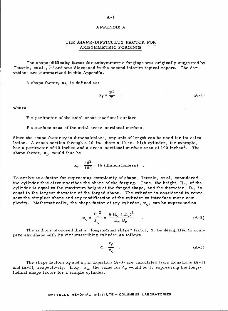
The shape-difficulty factor for axisymmetric forgings was originally suggested byTeterin, et al., (1) and was discussed in the second interim topical report. The deri-vations are summarized in this Appendix.
A shape factor, xf, is defined as:
f =-(A-i)
where
P = perimeter of the axial cross-sectional surface
F = surface area of the axial cross-sectional surface.
Since the shape factor xf is dimensionless, any unit of length can be used for its calcu-lation. A cross section through a 10-in. -diam x 10-in. -high cylinder, for example,has a perimeter of 40 inches and a cross-sectional surface area of 100 inchesZ. Theshape factor, xf, would thus be
402f 0? 16 (dimensionless)xf-100
To arrive at a factor for expressing complexity of shape, Teterin, et al, consideredthe cylinder that circumscribes the shape of the forging. Thus, the height, Hc, of thecylinder is equal to the maximum height of the forged shape, and the diameter, Dc, isequal to the largest diameter of the forged shape. The cylinder is considered to repre-sent the simplest shape and any modification of the cylinder to introduce more com-plexity. Mathematically, the shape factor of any cylinder, xc, can be expressed as
Pc 2 4 (Hc + Dc)2xc = F7 H D (A-2)
The authors proposed that a "longitudinal shape" factor, a, be designated to com-pare any shape with its circumscribing cylinder as follows:
XfS=--(A-3)xc
The shape factors xf and xc in Equation (A-3) are calculated from Equations (A-l)and (A-2), respectively. If xf = xc, the value for a•c would be 1, expressing the longi-tudinal shape factor for a simple cylinder.
BATTELLE MEMORIAL INSTITUTE- COLUMBUS LABORATORIES
A-2
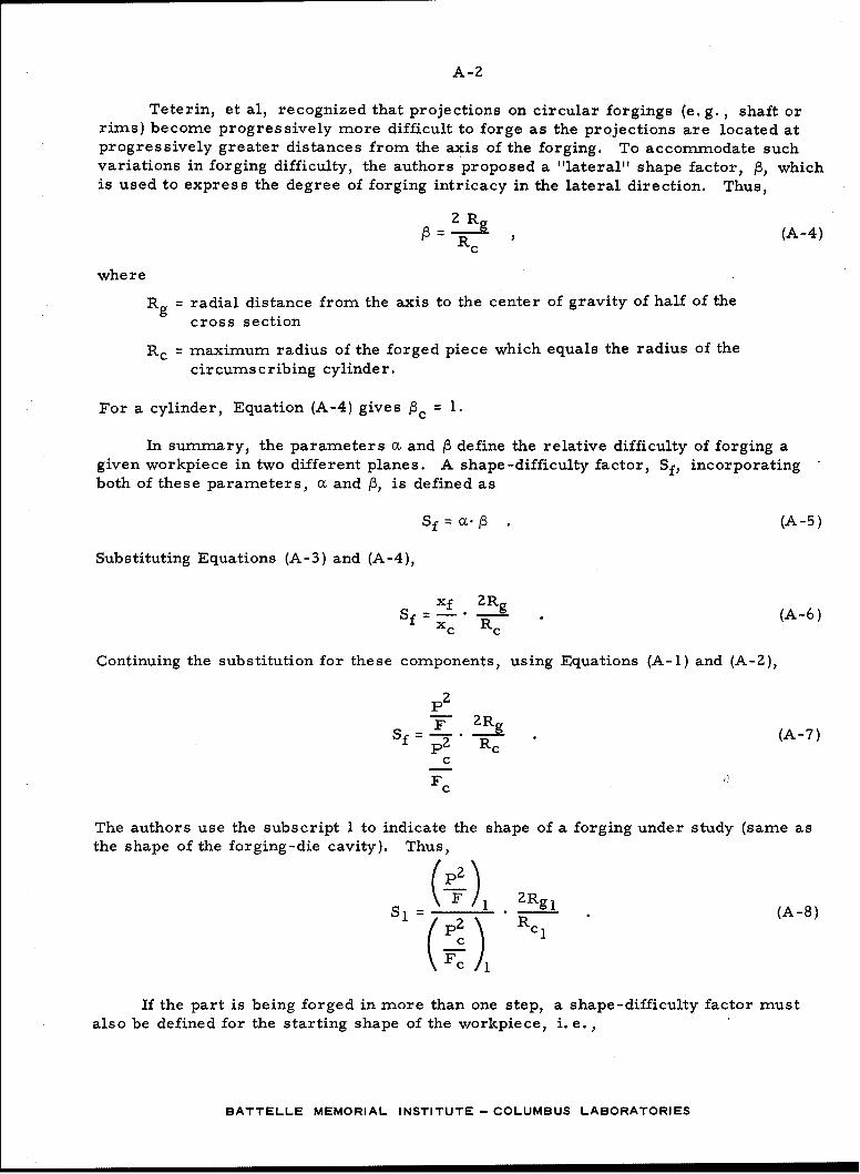
Teterin, et al, recognized that projections on circular forgings (e. g. , shaft or
rims) become progressively more difficult to forge as the projections are located at
progressively greater distances from the axis of the forging. To accommodate such
variations in forging difficulty, the authors proposed a "lateral" shape factor, 3, which
is used to express the degree of forging intricacy in the lateral direction. Thus,
2 Rg=3 , (A-4)
Rc
where
Rg = radial distance from the axis to the center of gravity of half of thecross section
Rc = maximum radius of the forged piece which equals the radius of the
circumscribing cylinder.
For a cylinder, Equation (A-4) gives Pc = 1.
In summary, the parameters a and /3 define the relative difficulty of forging a
given workpiece in two different planes. A shape-difficulty factor, Sf, incorporating
both of these parameters, a and P, is defined as
Sf . (A-5)
Substituting Equations (A-3) and (A-4),
=xf ZRg (A-6)xc Rc
Continuing the substitution for these components, using Equations (A-i) and (A-2),
P2
Rc (A-7)Sf=p2 "Rc
c
Fc
The authors use the subscript 1 to indicate the shape of a forging under study (same as
the shape of the forging-die cavity). Thus,
Si = _ _ . 2Rgl (A-8)PC 1
If the part is being forged in more than one step, a shape-difficulty factor must
also be defined for the starting shape of the workpiece, i. e.,
BATTELLE MEMORIAL INSTITUTE- COLUMBUS LABORATORIES
A-3 and A-4
(Z 2Rg
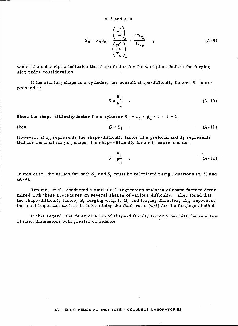
so = mogo = " (A-9)
kF
where the subscript o indicates the shape factor for the workpiece before the forgingstep under consideration.
If the starting shape is a cylinder, the overall shape-difficulty factor, S, is ex-pressed as
S i (A-10)Sc
Since the shape-difficulty factor for a cylinder Sc = -c = I • 1 = I,
then S = S1 (A-Il)
However, if SO represents the shape-difficulty factor of a preform and S1 representsthat for the final forging shape, the shape-difficulty factor is expressed as
S = S . (A-12)so
In this case, the values for both S1 and So must be calculated using Equations (A-8) and(A -9).
Teterin, et al, conducted a statistical-regression analysis of shape factors deter-mined with these procedures on several shapes of various difficulty. They found thatthe shape-difficulty factor, S, forging weight, Q, and forging diameter, Do, representthe most important factors in determining the flash ratio (w/t) for the forgings studied.
In this regard, the determination of shape-difficulty factor S permits the selectionof flash dimensions with greater confidence.
BATTELLE MEMORIAL INSTITUTE -COLUMBUS LABORATORIES
APPENDIX B
EMPIRICAL FORMULAS FOR PREDICTING FLASHDIMENSIONS AND FLASH WEIGHT
BATTELLE MEMORIAL INSTITUTE - COLUMBUS LABORATORIES
B-1
APPENDIX B
EMPIRICAL FORMULAS FOR PREDICTING
FLASH DIMENSIONS AND FLASH WEIGHT
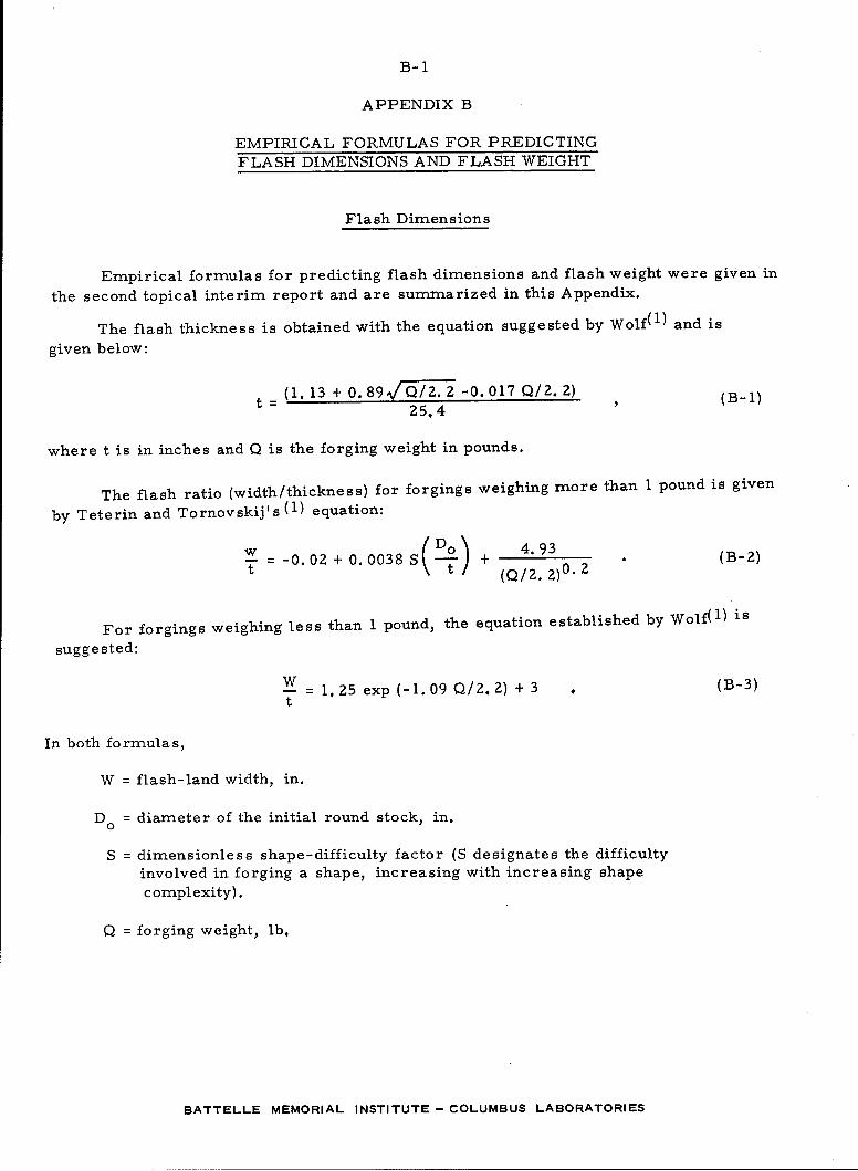
Flash Dimensions
Empirical formulas for predicting flash dimensions and flash weight were given in
the second topical interim report and are summarized in this Appendix.
The flash thickness is obtained with the equation suggested by Wolf(1 ) and is
given below:
t=(1.13 + 0.89/Q/2.2 -0.017Q/2.2) (B-i)25.4
where t is in inches and Q is the forging weight in pounds.
The flash ratio (width/thickness) for forgings weighing more than 1 pound is given
by Teterin and Tornovskij's (1 ) equation:
w- = -0.02 + 0.0038S(DO) + 4.93 (B-2)t \t (Q/2. 2)0. 2
For forgings weighing less than 1 pound, the equation established by Wolf(1 ) is
suggested:
S= 1. 25 exp (-1. 09 Q/2. 2) + 3 . (B-3)
t
In both formulas,
W = flash-land width, in.
Do = diameter of the initial round stock, in.
S = dimensionless shape-difficulty factor (S designates the difficulty
involved in forging a shape, increasing with increasing shapecomplexity).
Q = forging weight, lb,
BATTELLE MEMORIAL INSTITUTE- COLUMBUS LABORATORIES
B-2
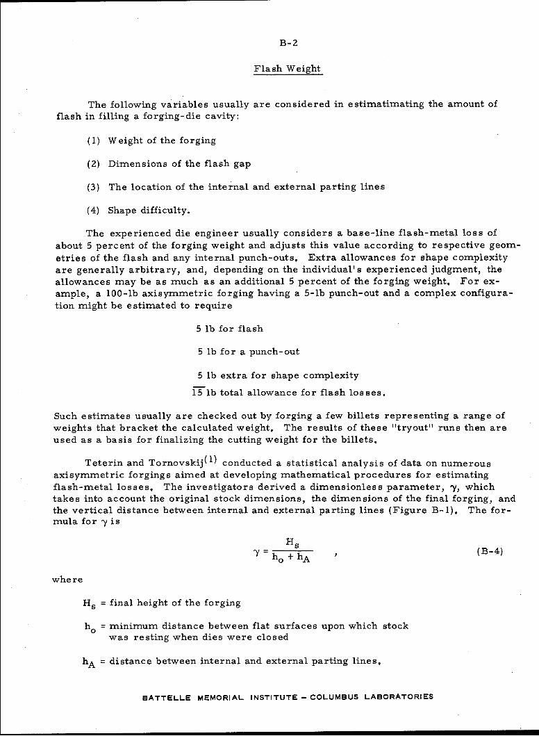
Flash Weight
The following variables usually are considered in estimatimating the amount offlash in filling a forging-die cavity:
(1) Weight of the forging
(2) Dimensions of the flash gap
(3) The location of the internal and external parting lines
(4) Shape difficulty.
The experienced die engineer usually considers a base-line flash-metal loss of
about 5 percent of the forging weight and adjusts this value according to respective geom-
etries of the flash and any internal punch-outs. Extra allowances for shape complexityare generally arbitrary, and, depending on the individual's experienced judgment, theallowances may be as much as an additional 5 percent of the forging weight. For ex-ample, a 100-lb axisymmetric forging having a 5-lb punch-out and a complex configura-tion might be estimated to require
5 lb for flash
5 lb for a punch-out
5 lb extra for shape complexity
15lb total allowance for flash losses.
Such estimates usually are checked out by forging a few billets representing a range ofweights that bracket the calculated weight. The results of these "tryout" runs then areused as a basis for finalizing the cutting weight for the billets.
Teterin and Tornovskij( 1 ) conducted a statistical analysis of data on numerous
axisymmetric forgings aimed at developing mathematical procedures for estimating
flash-metal losses. The investigators derived a dimensionless parameter, 'Y, whichtakes into account the original stock dimensions, the dimensions of the final forging, andthe vertical distance between internal and external parting lines (Figure B-1). The for-mula for -y is
Hs(B-4)
"ho + hA
whe re
Hs = final height of the forging
ho = minimum distance between flat surfaces upon which stockwas resting when dies were closed
hA = distance between internal and external parting lines.
BATTELLE MEMORIAL INSTITUTE- COLUMBUS LABORATORIES
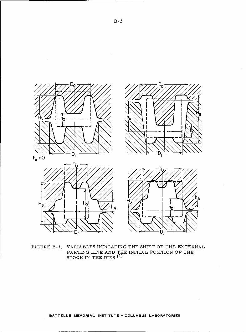
B-3
4 -- s
\\ \0\\
"hA= D, DI \ 'hA 0
I - sh ho i
FIGURE B-I. VARIABLES INDICATING THE SHIFT OF THE EXTERNALPARTING LINE AND THE INITIAL POSITION OF THESTOCK IN THE DIES (1)
BATTELLE MEMORIAL INSTITUTE - COLUMBUS LABORATORIES
B-4
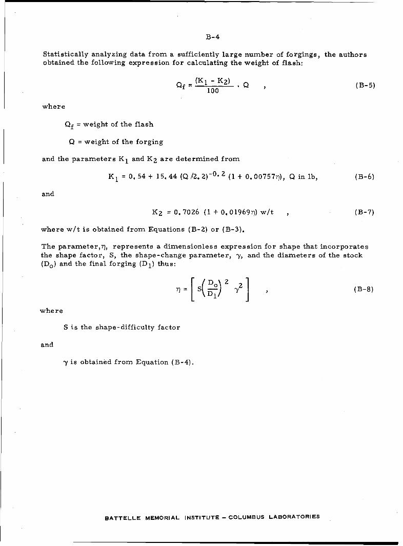
Statistically analyzing data from a sufficiently large number of forgings, the authorsobtained the following expression for calculating the weight of flash:
Qf( 2) 10 , (B-5)
where
Qf = weight of the flash
Q = weight of the forging
and the parameters K 1 and K 2 are determined from
K 1 = 0.54 + 15.44 (Q /2. 2)-0 2 (1 + 0. 00757-0), Q in lb, (B-6)
and
K 2 = 0. 7026 (1 + 0. 01969r)) w/t , (B-7)
where w/t is obtained from Equations (B-2) or (B-3).
The parameter,?), represents a dimensionless expression for shape that incorporatesthe shape factor, S, the shape-change parameter, y, and the diameters of the stock(DO) and the final forging (Dl) thus:
D 2 i (B-8)
whe re
S is the shape-difficulty factor
and
y is obtained from Equation (B-4).
BATTELLE MEMORIAL INSTITUTE- COLUMBUS LABORATORIES
APPENDIX C
SYMBOLS USED IN THE FORTRAN PROGRAM
BATTELLE MEMORIAL INSTITUTE - COLUMBUS LABORATORIES
C-1
APPENDIX C
SYMBOLS USED IN THE FORTRAN PROGRAM
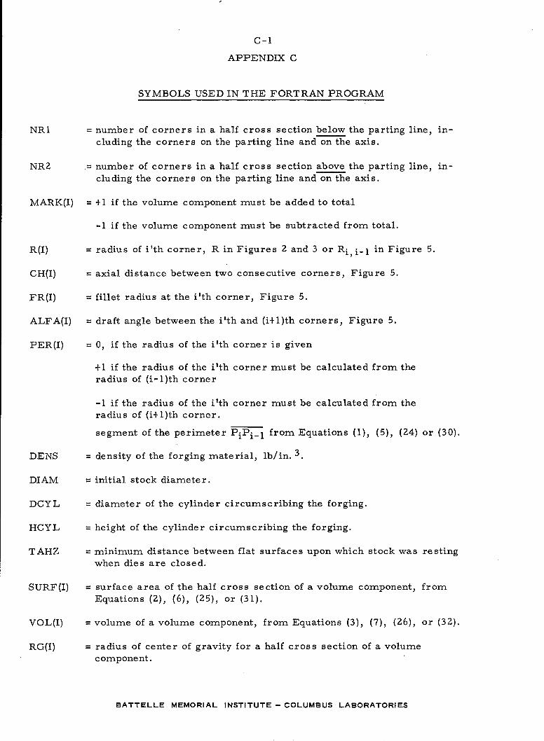
NRl = number of corners in a half cross section below the parting line, in-cluding the corners on the parting line and on the axis.
NR2 = number of corners in a half cross section above the parting line, in-cluding the corners on the parting line and on the axis.
MARK(I) = +1 if the volume component must be added to total
-1 if the volume component must be subtracted from total.
R(I) = radius of i'th corner, R in Figures 2 and 3 or Ri, i_ in Figure 5.
GH(I) = axial distance between two consecutive corners, Figure 5.
FR(I) = fillet radius at the i'th corner, Figure 5.
ALFA(I) = draft angle between the i'th and (i+l)th corners, Figure 5.
PER(I) = 0, if the radius of the i'th corner is given
+1 if the radius of the i'th corner must be calculated from theradius of (i-l)th corner
-1 if the radius of the i'th corner must be calculated from the
radius of (i+l)th corner.
segment of the perimeter PiPi- 1 from Equations (1), (5), (24) or (30).
DENS = density of the forging material, lb/in. 3.
DIAM = initial stock diameter.
DCYL = diameter of the cylinder circumscribing the forging.
HCYL = height of the cylinder circumscribing the forging.
TAHZ = minimum distance between flat surfaces upon which stock was restingwhen dies are closed.
SURF(I) = surface area of the half cross section of a volume component, fromEquations (2), (6), (25), or (31).
VOL(I) = volume of a volume component, from Equations (3), (7), (26), or (32).
RG(I) = radius of center of gravity for a half cross section of a volumecomponent.
BATTELLE MEMORIAL INSTITUTE- COLUMBUS LABORATORIES
C-2
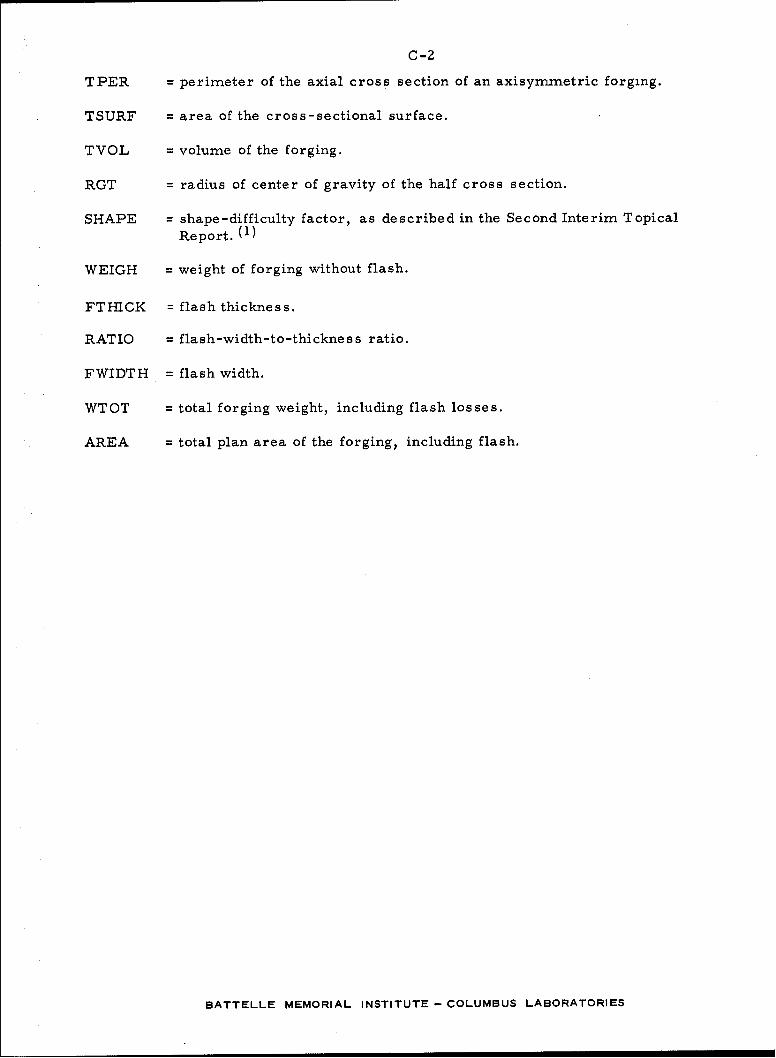
TPER = perimeter of the axial cross section of an axisymmetric forging.
TSURF = area of the cross-sectional surface.
TVOL = volume of the forging.
RGT = radius of center of gravity of the half cross section.
SHAPE = shape-difficulty factor, as described in the Second Interim TopicalReport. (1)
WEIGH = weight of forging without flash.
FTHICK = flash thickness.
RATIO = flash-width-to-thickness ratio.
FWIDTH = flash width.
WTOT = total forging weight, including flash losses.
AREA = total plan area of the forging, including flash.
BATTELLE MEMORIAL INSTITUTE- COLUMBUS LABORATORIES
APPENDIX D
FORTRAN COMPUTER PROGRAM FOR CALCULATING DESIGNPARAMETERS IN AXISYMMETRIC FORGINGS
BATTELLE MEMORIAL INSTITUTE- COLUMBUS LABORATORIES
D-1
0 aC 0 00000000cl00
0C 0000 00 C)Ca 0 c0
4444V44v4444444444444444
6p bF t. waaa6pW, W
ip.~~~~a a- 4At Ai A t . W.
V. w tpipa tp ta t.
V4~~a a ep4 * aA t wt$A tAa~ 4Awwtp* A w
w w1A.W bl.aa-*A~~~~ ~ ~ ~ 0w6AV#At AtfA OR t
a~~to wta (f wa
Vta b.a W. i 4 I 4
alAal aatAl if, a 4 ba
Y. aaFaw
W a 4F if o... V W 6F -aa. *~a Vff a ta6a
w 6F tp 0. A 6Fba6aEA EpIdA 6 #A Ir- I ba UP to tp
wa ak a #A w A6 ,. aaV~a V ~ a *FkFVaa t a V
6 t b a v .v w w to b, a. av ip w 6 * Ea EVý~~~~ v aab .'
LF9 VF. W c a aaFb.
Yaa t. v WtaWW -a- a. a p a p a p ta 'r- ap- F Or
aP1 A - aL V4 bp h. a-,A P
t. a1 ai W, t U' tr tP- b- aýW
a-a v aa _w cv a
ae a. f. a.ba, V. a a'I
a.F Wa a vv- a F v--v
BATTELLE MEMORIAL INSTITUTE - COLUMBUS LABORATORIES
D- 2
0 00 000 *0 0pi
6A 44A444444o4A4
im 4 4A p 6AfA Vbp 4pp
ip ip 4A 4 6A 4 to ipto~~ ~ ~ ~ qp# ppAI^W4
p op 6p p
p p p p p 4A W #4AWA p pAf
p" p k"Vp pA pp 4 pPfAtA#A# #AP W, WAR
pp #A Aw P w 6A FAA4A#
fp w I 6(APP P *A IAP*
fp wp pA tp fp pAppF 4P p p
ip~~~ ~ ~ ~ pA p" pA6 ot i A4
bp~ pF p pip ~ ~~ wp pp# f
p p p iP P 6p 6p PA t. PA P PP pP
pp pFW p pp Wpv pp
if t w w b w p *p
ip vpp
V ~ ~ ~ ~ ~ ~ p ppt c pwVV
p pp pp v p to .bp pF
QP P b.ppp p V. 46 v w Ib Pp
p F p A ppp ýp pF pF pFq P V
w~~~ ~ ~ v p4po.iV4pte V4 bg ýp p pA pA%
p ppp pp p t&bVp p. pF
vVP PPpp tp tp
6p p PP pppwp
P. PP P W_ p P bp pIF~~ #p pf pAv ~ ~ ~ ~ ~ ~ ~ ~ ~ p ppv1-9 vv4 ývv .
BATTELL ppORA ppTTT CLMBSLBRTRE
D-3
PROGRAm SHAPF(TNPI.ToUTPUTTAPEt~=INPUTTAPE-6 OUTPUT)C**DETERMI!NATION OF SHAPEFfACTOR IN FORGING
C**MOOTFCATION IF BEGINNTNeA AND END CORNERS AREC** NOT FLAT(COMMON R(100),NPCH(100),ALFA(100),PER(100),SURF(100),VOL(100),iPGUOnO) FP (100') MARK (100) ,DFLH( 10.0).pl=,3.1419q?693A
C*4s ~R,(J)m RADIUS O)F .TI+E FORG.ING. AT VARIOUSC ** LOCATIONS
C** ~NP= NU.M8ER OF CORNERS. ON ONE HALF..OF THEC** FORGINGC** ~~CH (I)!FAXIAL.JDIlSTANCE. BETWfENJ-TH_.ANDC** (!-H)TH CORNERC** ~~ALFA (1).M ANGLE .OF-.THE- TAPER .AT .THEI-TC** CORNER WITH THE AXIS
.c*4 PER.(1)= ~PFRTMETER OF A..SLTCEC** qliRF(I)=SURFACE AREA OF A qLICEcl* v ~~~OL( I v 0L IME -F -.A -SL.CE-....
C ** FRUT)= FILLET RADIUS BETWEEN THE I-TH ANDC ** (I-I)TH.CORNERS =F(I0.9 FOR. SHARP CORNER
MAR'K(I):1 FOR INCREASING VOLUMEC ~~MARK,(1, Y-1 .FOR. OECP!ASING .VOLUME
C** r\PI=N'JMRFR OF CORNERS FROM REGTN TO PARTING LINEC** ~ NP?=NIHIMRR OF COPNFPS FROM PARTING-LINE, TP-ENDC** TN PFP(T) WF STORE SIGNS TO CALCULATE SOME R(I)S
PEA!. 21,NIP1,NR;,PRINT 2?,NR1,Np?
NPO(NQ1-1)*?+Npl*NPDM (NPI.-1)
PRINT86no 8111,$Npnm,pPEAD 8?,gMARK(T),P (I) eCH (1) 9FP.(.).,ALFA (1),9PER(I)PRINTF8i? MARK (I ) R I),CHCI) ,FP( I) eALFA(T') ,PER (I)TFCIE(O.1)GO TO 8_]
pERK(1-1)= APRK ( T)
p I-i) =R (I)rH H1-1) =CH,( )FR(I-I)=FR (I)
Al A ýFA (1 +1_)=ALFA (T) __. . . . .. ..
PE.A!) 8?.-M-A'R-K(-N'n),R(NRD),CH(NRD)qFR(NRfl)+,ALFA(NRD)q0ER(NRD)pRINIT82,MARK.(NRO)oR(NRD) ,CH(NRD) ,FR(NRO)),_ALFA.(NRO) ,PER (NRD)
NR(pm=Npr3,
nO 8j1=N~r)PqN!Rmq
PRINT8PM.ARPK .(I.R( I0)__jCH( I) FR( I) ,ALFA(I) ,PER (I)
TF I(T9 EQ.JRflP) SO _TO 83M4RK (j-_])'=MAPK (1)PfR(T-1 )=PFER(T)
r H (I 1-1) =CH. (J)
BATTELLE MEMORIAL INSTITUTE - COLUMBUS LABORATORIES
D -4
FR (II) FR T)A 3 11L F A i +! i =nLF A (T)
READ) 8?,MAPK(NP),q(NR.),CHCNP),FRCN.R).,ALF.A(NR)PRINT82,oMAPK(NP) , )R(NR)t CH (NQ) FR NR) .ALF4CNR)NRM.N=NP_-In084T=1 ,NRMTN,?
QFCE.1)G-0 T n, !44yF(PCI)eNF.A.)C,) TO R4.ANG3LF=ALFAC ,T-P)ANGLF=ANGLF *PT/iRnoTF(.PER(I). L.T.O.'CO To 85R CI)=R I-?) -PFP (11*TAN (ANGLE) *CH CI)p =11 R CJ)SO To 84
85..ANGLE:ALFA(T)ANGLE=ANGLF*0T /TR A(CI)=RC(.T+I)-.PER (1)*TAN (ANGLE) *CHCI1#1)
p CI-])=R T)A4 CONTINUE
PRINT229NRPRI NT24pPINT239(RCT),y=19NR)PPRINT 2PR1NT23, CCH(t) ,T1,NR).PRINT ?9PRINT23, (FR(Tl oT=l ,NR)PRINT27PRINT23, (ALFA( T)% =1 -NR)PRINT23, (PERCI) ,T~l.NR.)PRINT?], (MARK(T ),T=1 NR)READ ?3,OENS~flTAM,DCYLTAHZTAHAHCYLPR4IN-T?.2,nENSD)TAM.DCYL 'TAHZTAHAHCYLC** 0 F N 5= DEN SITT.Yt** DIAM=STOCK DIAMETERC** DCYL=LARGEST DIAMETER OF-FORGINGC** TAHZ=MINIMUM DISTANCE BETWEEN FLATS
C ** TAH=ISAC Y~TEEN JNJERN AL- AJNDC* EXTERNAL PARTING LINESC** ~~~HCYL=,TOTALHEI~GHT OFF.ORGING
TVOL=O.TPER=OeTRGS=O.
3?' ALFA(I)=ALFA (T)*PT/IRO.KIL IM=M'R-1C** START CALCULATIONS
TFC(ALFA(T-1).Eo.o.)Go TO 41C** THIS* CHECKS THE PARTING LINE WHICH ISC** ~~CONSIDERED ..AS_.CYLINQER
nIVF=AlFA CI-?) -ALFA CT)RFTA=AHS (01FF)EP CT) =RFTA*FR(T)
R2=HFTA/?o
BATTELLE MEMORIAL INSTITUTE - COLUMBUS LABORATORIES
D-5
T?=TAN CR?)
FR1FPPCT) *T?_n)FLRM:FRl*STN(Al.FA (I-2))r)ELRP =FRj *tT I A I_ FACTI))C** CORNIER RADIUS WAS ORIGINALLY STORED AT
C ** ROTH R(I) AND RUT-I)rFLHdI)=F~R1*CO5(ALFA(I).)0FLH(I)=AR9(CDEIH(I))nELHCT-I) =FRl*CnS (ALFA (1-?)_)nFLHCI-1=ARSCDFIH(T-1))TAHrnE.HC ( T) +r)FIH ( T1-isHETA=SIN CAFTA)TAS=FR (1) *42* (RTA-SRETA) /2.TAX(S=2**FR CT) **3*5?**3/ (3.*TAS)PALF?=ARS(ALFA(T-2))A~AM M rA=82+*0,5~* PT_-PAL F2
c* * mfo IFY H FRPErF(ALFA(T-2).LrT.0.)C,AMllMA=O.5*PI-82-PALF2rsAtMA=ARq (GAMMA) 5TF(ALFA(T).,GTAtFAC1-?_))GO To 5r)FLX= (FR(I) /C;?-TAXS) *STN (GA.MMA).PS=R (I) *F[_LX
5? CONTTNIIFJ
PC I-ti R CT-i) +nlLPM11=R() +P CT-I)
V/OL Cl) =PT* (R!RMT*TAH/3.-TTAS*2.,*RS)PGCON=RTPMI/ (l,*s1)p G I ) =(R GCO N* S *O,5* TAH- T AS*P S), /SUR-F T-)
42 cONTTIN(EmiOW CALCULATF. F~oPTHE TRUNCATDCN
C~i AS DEFINED BY POTNTS 1-1 AND 1-2TAHl=CH( T)-OELH CT-I )DELHC I-?)_,_.I C* CHCT)=HEiGHT BETWEEN CORNERS STORED ATC*BOTH CHCT_ AN -±4T1)
43 CON7T NUF
50RFCI-I)=PTl *n,c;*TAHI
VOLCT-)=T*TAH14$RIRM1/3*nEN~cIN(ALFAC!-'>))7 .FCALFACT-;?),Eno..)tFN1l.PERCT-l)=ARS((P(T-1)-P(I-2))/flEN)PG I-I.)=PTRM1 /(l.*R~l)
TABS=A6S CTAR)_l
7F(TA.BS.GT.0.0OnO0l)Cl) TO 31
PGl (-1) =O.\/OL Cr-i) =0GO To-3.
BATTELLE MEMORIAL INSTITUTE - COLUMBUS LABORATORIES
D-6
41 rONTTNUEC** CALCULATIONS FOR CYLTNDER AT PARTING LINE
C** AKII) FOR THE ADJACENT.TRUNCATED CONEPG (1=R (T) /?.cvOLR (1),IOR (I) *CHCH (1)
PEIR (.Tf=C-H.(T)TAH1=CH ( I-1 -fFLH(CI-?)oELH( I)=o.60 To 43
51 CON.TiNuEPALF2=AI.4(ALFA (I-2))
GFAMM 'A (T~* -2) LT?-P4L AF?* I- AL P+
sklA=~A3ARS (GAMMA)0*ELx( ( =FR( T) /C?-TAXS)*SIN(GAMmA)
TAS=.TASn'O To 52
31 CONT INUJETK=I.1n013pK=1 .3KK=IK-K
13?, PRINT133.KK.PFR(KK),SURF(KK),VOL(KK),RG(KK)
ORINTl33,IRFTAI)FLH(I),DELH(T..1),TAHR(T).RCI1m1),TAHlGAMqFT8=8ETA*1R0.,pPRINT133, I ,IETgRRT2,S2,C2,FR1,DELRDELRM
131 CONTINUE.SU#F(NR)=0.VOL (NR)=0,PG (NR)=0.PER (NR) =A8 5ý((R (NR.) -.R.ONRI-11TPER=O.7 SURF = 0TVOL=Oo
C******CALCUJLATE PEPIMETFRPVOLUMEtSURFACE AND RADe OF CENT. OFC*****GPAVITvT
n,06l T=2,N.FMARKI.TPER=TPER+PER CT)
IF CMAR((T) _,_!I) FMARKZ-1T SURF TSkJPF +FMAP4K *SUPF (1)TVOL=TVOL+FMRKVLC)PGS~pGS+FMARK*PG (I)*SURF (I)
61 CONTINUEPG T =PG / T StJR FTSUPF=2.*TSUPPTPE.4=2.*TPFRPRINT 911PRINT67,TPE-Rpe,TSIRF TVOLtRGTC** STAIRT CALCULATION OF SMAKE FACT-OR
FXF=TPER**2-/TSIJPF
BATTELLE MEMORIAL INSTITUTE - COLUMBUS LABORATORIES
D-7
ALFS=EXF/EXCPCYL=DCYL/2.PETS =2,*RGT/Pc*YLSHAPE=ALFS*8ETe,PRINT 62,,SHAPRE_,ALFSRE.TSWEIGH=TvOL*DENSPRINT 63,WEjo.QqjTvo.L.
C** FOR FLASH THICKNESS WE USE WOLF-S FORMULA
FTATUO0.89*Tl**6*5uu.O.017*TlFTHI.CK c(.1.1,tF. 'lEA)15
C*41 FOR FLASH RATIO WE USE wOLF-S FORmULA IF WEIGHT ISC** ~~SNIALLE-P.-HAN 1 LJR$.QI.HERAI5_E_.TE.TLERN S FORMULA
TFCWEIGH.LT.3*)tGO TO 71
rO To 7271 PARTx-1. 094TI
pATIO=1 .?5*F2XP (PART) .3.72 .COQNTIj.NUE
FWIDTH*RATTO4&FTHICKPP I .T. _4,tk FTH KFWDJ ~ A1.oAMZHCYL/ (TAH7.TAHA)FTAý=SHAPF*O I A.Mi4*?GAM**R/ Y**2
FLAS`HW=(AK) -AKp2)*WETGH/1OO.
PRINT 65vWFIGH9FLASHW9WTOTODTQ.TuD CYL,2q.*FWjRTHAREA=PI*fTOT**P/4,PRINT 66oAREA
9.11. FORMAT (40H PFR.IMFTERSU5RF-A-C-EVLUMER OF C,AR-A-ITY)62 FORMAT(27H SHAPE DIFFICULTY FACTOR IS93F1505)63 FORMAT(32H FORGINC9, WFIGHT WTTHOUT FLASH 4_qSgIji5A5Is64 FORMAT (44H FLASH THICKNESSFL-ASH WIDTHFLASH RATIO ARE,3F15#5)65 FORMATC4I.HF0L~eTjNG WFIGHTFLASH WEIGHT9+oTAL WEIGHT,3FI5S.),66 FORMAT (38H THF -PROJECTED AREA INCLUDINr, FLASH ISfF15.5)67 FORMATC1IH PERTM4ET.ERzFj5,_5,9H SURFACEl!U1FA5ff5//,SH VOLUME.,F1595,2.
19H RADIu)5 OF C. OF CRAVITYtF1S,5)?A FORMAT(19H MATFRIAL OENSITYx AJ.A±.SOKDAEE ,1.,1
IH LARGEST DIAMETER =qF1O.4,/lOH4 HEIGHTS .,oF1Oo4)27 FORMAT(;?7H ANGLESBETWEEN CORNERS ARE)29 FORMAT(lRH FILLET RADII ARE25FORMAT(36H AXTA DSTANCES BETWEEN CORNERS ARE)
?4 FORMAT(25H RAnTT OF THE CORNERS ARE)22 .FORNIAT(IPH NUMRF-R-OF CORNERSo2l1 s)86 FORMAT(9?H INPUT DATA92N40 NUMRER CORNER OADIIAXIAL DISTANCE BETWE
lFN.CnRNEPS9F,Flj FT RAnIIDRAFT ANGLES)23 FORMAT(8FI0,4)
1-33 FORMAT(/T5,RF)P.3)21 FORMAT(8TIO)82 FORMAT(II0,6F.In,4)
END
BATTELLE MEMORIAL INSTITUTE - COLUMBUS LABORATORIES

D- 8
'C 0,
CD 0o C>
o C
0
o 01
C>C
Q 00
11, %fr r-- p.- P.-%i 0 m IL P- u)tr*m f-. C, m,
a CD 0 0 0:
*MM W c- cMin P- CN F- 0 - i . ýcm r-I nM-COOmmm4w4f-WL o NNM M 00 Q f-Ne N00 0 c 0z c0= 0 Q0>C 0 000000 CýCQC'C 'L C C00C ýC "CCC 0aQCC'C ' Da 0 0 000C -
z zlL, -M i I� -C jVI 1 FUN4---WCL ZIC4(I-p. C -.Ca .- rp- Ctý-* - r-m ?- I� C%, C
Ul .fti C 0 CO 0 000c . =c C~0 C Z ý 0 c C>C0 00000c C 41 0 C0'C0 000 I= 0 LjC C(C0 -
cl a, Z C
v- A- cr IL m ICr , A c ,4 4 m m C " 'N t - C c
Cr L c z cc C Ct C'- 0ý 0 C.C 4( C. CL . 'rC--. Cf- -0c0 ~ ý0=c r( V'-4= -C o_jcc mc .cI c~ IaD N>C J---.-m ( CC 00.-..-'44cD0 f_- Q > _ C--- .0 ILJ t jc c
2O C 0 O 0 0 0 0 0 o o o ~ 0 0 C O Ou i i LLJ i0 0 0 C 0 0 . 0 0 0 00 0 00 0
-r ft z~L. ~ U ~ L) U J.....J U U )...'~L .~ ' Ufr. M LL W
UL c W. op W,~ >
BATEL MEORA INTTT -CLUBU LABRATRIE