111 11111 11111 11111 11111 1111ll111111111111 - nasai11111111 111 11111 11111 11111 11111...
TRANSCRIPT
I11111111 111 11111 11111 11111 11111 1111ll111111111111 N6922173
One Source. One Search. One Solution.
DESIGN AND FABRICATION OF THE BRAYTON CYCLE HIGH PERFORMANCE COMPRESSOR RESEARCH PACKAGE FINAL REPORT
AIRESEARCH MFG. CO., PHOENIX, ARlZ
29 NOV 1967
US. Department of Commerce National Technical Information Service
https://ntrs.nasa.gov/search.jsp?R=19690012811 2020-05-05T16:25:21+00:00Z
One Source. One Search. One Solution.
Providing Permanent, Easy Access to U.S. Government Information
National Technical Information Service is the nation's largest repository and disseminator of government- initiated scientific, technical, engineering, and related business information. The NTlS collection includes almost 3,000,000 information products in a variety of formats: electronic download, online access, CD- ROM, magnetic tape, diskette, multimedia, microfiche and paper.
Search the NTlS Database from 1990 forward NTlS has upgraded its bibliographic database system and has made all entries since 1990 searchable on www.ntis.gov. You now have access to information on more than 600,000 government research information products from this web site.
Because many Government agencies have their most recent reports available on their own web site, we have added links directly to these reports. When available, you will see a link on the right side of the bibliographic screen.
NTIS can now provides the full text of reports as downloadable PDF files. This means that when an agency stops maintaining a report on the web, NTlS will offer a downloadable version. There is a nominal fee for each download for most publications.
link to Full Text Documents at Government Web Sites
Download Publications (1997 - Present)
For more information visit our website:
\IV\IV\IV= nt 3 s ,gov
US. DEPARTMENT OF COMMERCE Technology Administration
NASA CR-72533 APS-5269-R
FINAL REPORT DESIGN AND FABRICATION
OF THE BRAYTON CYCLE HIGH mRF’ORMANCE COMPRESSOR RESEARCH PACKAGE
Prepared for
National Aeronautics and Space Administration
by
AiResearch Manufacturing Company of Arizona
November 29, 1967
Contract NAS3-9427
Technical Management NASA L e w i s Research Center
Cleveland, Ohio
Space Power Systems Division Jams H. Dunn
AIRESEARCH MANUFACTURINP COMPANY OF ARIZONA A Olv'l010Y OI T M t m A I . I T T C D I L O ~ A T l O *
L*OP.*l". .1120N.
I ABSTRACT
AiResearch Manufacturing Company of Arizona designed, fabricated, performed acceptance testing and delivered to the NASA a Brayton-Cycle Compressor Research Package under NASA Contract NAS3-9427.
The research package is aerodynamically identical to the compressor used in the NASA Brayton Rotating Units (BRU) to be delivered under the same contract, This compressor research package will be utilized at the NASA Lewis Research Center for complete component performance evaluation.
I
AIRESEARCH MANUFACTURING COMPANY OF ARIZONA I DIYI.IO* O r 1 ° C O I m M C l T C O I L O R I T I O *
P * O C * I X ."1*0*.
TABLE OF CONTENTS
1 .O INTRODUCTION
2 .O DETERMINATION OF DESIGN CONDITIONS
3 .0 COMPRESSOR DESIGN
3 .1 Aerodynamic Design Approach 3 .2 Aerodynamic Design Data 3.3 Compressor Wheel Stress Analysis 3.4 Critical-Speed Analyses 3 .5 3.6 compressor Instrumentation
Bearing and Seal Design Data and Drawings
4.0 GENERAL UNIT DESCRIPTION
5 -0 COMPRESSOR RESEARCH PACKAGE ACCEPMNCE TESTING
ATTACHMENTS: Drawing 699683 Drawing 699680 Drawing 699667 Drawing 699767 Drawing 699768 Drawing 699681 Drawing 358500
APS-5269- R Page i
Page
1
2
3
3 5
11 15 20 24
29
AIRESEARCH MANUFACTURING COMPANY O F ARIZONA I 0111S1011 O r 111 01111~1 C O S L O I I I I O W
Figure
1.
2.
3. 4.
5 .
6.
7.
8.
9. 10
11.
12 0
13 . 14
LIST OF FIGURES
BRU Compressor Wheel
Compressor Impe l l e r Diagrams
C r mpressor Diffuser and Sc ro l l Velocity Diagrams
NASA BRU Compressor Rotor and S ta to r Physical Dimensions
NASA BRU Compressor I m p e l l e r Radial Stress Di s t r ibu t ion
NASA BRU Compressor Impeller Tangential Stress D i s t r ibu't ion
System Used i n C r i t i c a l Speed and Bearing Load Ana1ysi.s of The BRU Compressor Research Package
BRU Compressor Research Package C r i t i c a l Speeds A s A Function of Mounting F l e x i b i l i t y For Both Mounts Equal
Bearing Loads For BRU Compressor Research Package
Bearing System Life, B1, NASA BRU Compressor Research
Bearing Power Loss For NASA BRU Compressor Research Package
Compressor Research Package Mounted i n Acceptance T e s t Rig-Front V i e w
Compressor Research Package Mounted In Acceptance T e s t Rig-Left Side View
Compressor Research Package Mounted In Acceptance Test Rig-Right Side V i e w
Page
4
7 8
10
13
14
17
18
19
2 1
22
31
32
33
APS-5269- R Page ii
LIST OF TABLES
Tab l e - 10 Pressure, Temperature and Eff ic iency A t
Stations Through The Compressor
2. Compressor Research Package Operating Speed Range
30 Unidirectional Bearing Loads Assumed For Bearing Analysis, Compressor Research Package
I 4. Compressor Research Package Bearing System B1 Life (TBO)
I
I
I
I
Page
9
16
23
23
APS-5269 -R Page iii
' 1x1 AIRESEARCH MANUFACTURING COMPANY OF ARIZONA
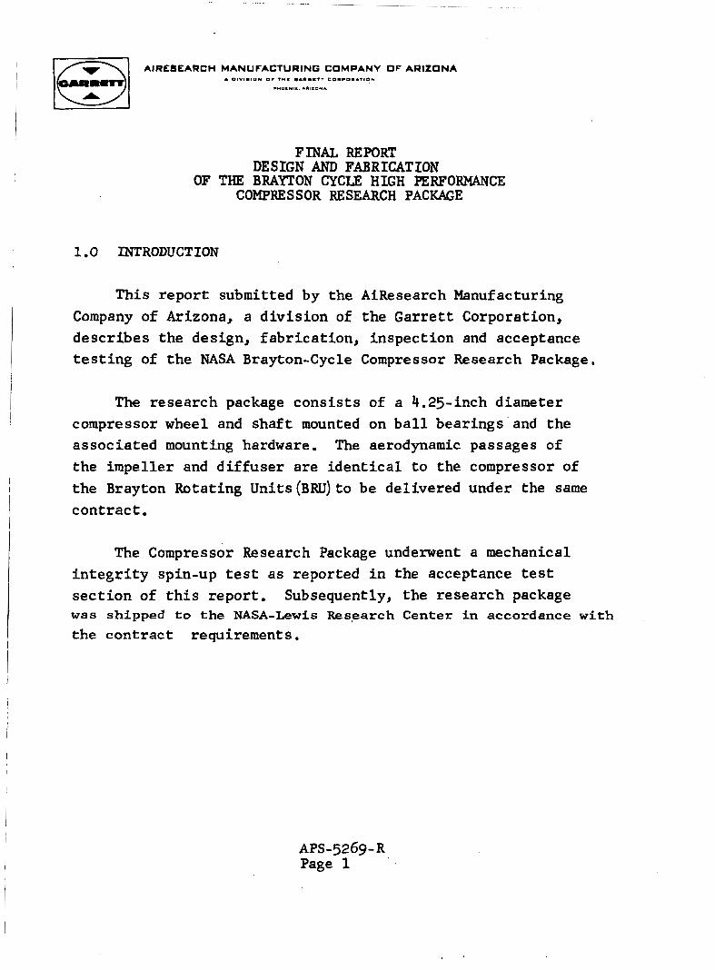
FINAL REPORT DESIGN AND FABRICATION
OF THE BRAYTON CYCLE HIGH PERFORMANCE COMPRESSOR RESEARCH PACKAGE
1 .O INTRODUCTION
This report submitted by the AiResearch Manufacturing Company of Arizona, a d iv i s ion of the Garre t t Corporation, descr ibes the design, fabr ica t ion , inspect ion and acceptance t e s t i n g of the NASA Brayton-Cycle Compressor Research Package.
The research package cons i s t s of a 4.25-inch diameter
The aerodynamic passages of compressor wheel and sha f t mounted on b a l l bearings ' and the associated mounting hardware. the impeller and d i f fuse r a re iden t i ca l t o the compressor of the Brayton Rotating Units (BRU) t o be delivered under the same con t rac t
The Compressor Research Package underwent a mechanical i n t e g r i t y spin-up tes t a s reported i n the acceptance tes t sec t ion of t h i s repor t Subsequently, the research package was shipped to the NASA-Lewis Research Center in accordance with the contract requirements.
APS-5269- R Page 1
2.0 DETERMINATION OF DESIGN CONDITIONS
I
During the preliminary design phase of the BRU Program, system s tudies were performed t o determine trends toward est:ablishing the opt imum BRU configuration and i t s correspond- ing design points a t th ree representat ive power levels-- 2.25 kwe, 6.0 kwe, and 10.5 kw, Extensive parametric ana lys i s evolved a system design which yielded high cycle e f f ic iency and conditions favorable to the BRU throughout the 2.25 kwe t o 10.5 kwe power range.
ne t e l e c t r i c a l output,
I The compressor design conditions r e su l t i ng from t h a t analysis a t the reference design power l eve l of 6 .0 kwe a re as follows:
Working f l u i d
Compressor i n l e t pressure ( t o t a l )
Compressor i n l e t temperature ( t o t a l ) Compressor pressure r a t i o Compressor mass flow ra t e ' Compressor ro t a t ing speed Compressor spec i f i c speed
XeHe mixture , e q u iva l e n t molecular weight
13.5 psia
54 0 OR
1.9 0.756 lb/ sec. 36,000 rpm
= 83.8
0.11
3.0 COMPRESSOR DESIGN
3.1 Aerodynamic Design Approach
A f t e r reviewing the compressor design condi t ions obtained from the s y s t e m a n a l y s i s , i t was determined t h a t an exact sca le of an e x i s t i n g compressor s tage would y i e ld exce l l en t e f f ic iency . To ass is t i n reaching t h i s conclusion, the measured performance .
o f t he e x i s t i n g compressor was u t i l i z e d , i n a computer program t o p red ic t the performance in the XeHe mixture and appropriate cor rec t ions w e r e made t o account f o r expected e f f i c i ency changes. Similar p a s t performance predict ions based on air data f o r com- pressors t o be operated in gases other than a i r have proven t o be r e l i a b l e .
The only new component required-- the scrol l - -was designed t o provide a minimum t o t a l pressure loss from the d i f f u s e r e x i t t o the s c r o l l e x i t using standard s c r o l l design p rac t i ce . I n addi t ion , only minor mechanical d i f f u s e r modification would be required. Fur ther study indicated t h a t based on the e x i s t i n g technology, i t was not l i k e l y t h a t a new compressor designed specifically for the BRU would exceed the expected efficiency of
a scaled stage. Estimates of e f f ic iency deterioration due t o lower Reynold's number, smal le r and less accura te par t s , and h igher . r e l a t i v e a x i a l c learance l e d t o a predicted design e f f i c i ency of g r e a t e r than 80 percent .
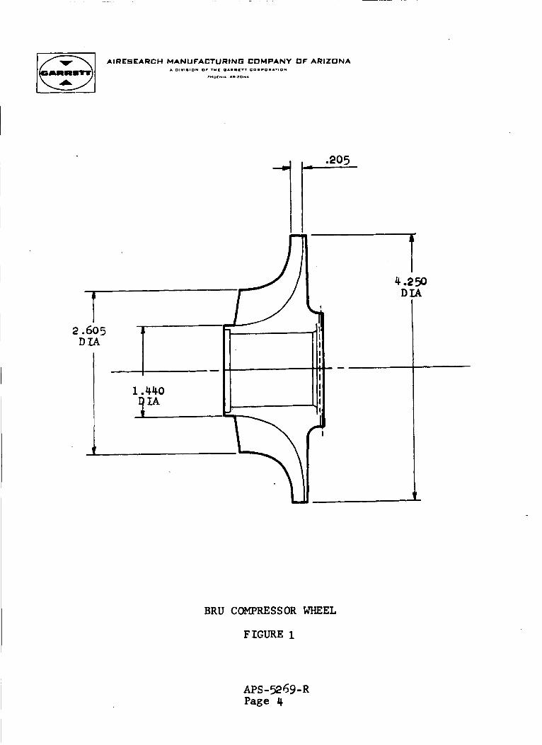
The f i n a l ca lcu la ted sca l e f a c t o r was 0.514. The meridional dimensions of t he scaled wheel a r e given i n Figure 1.
I
AIRESEARCH MANUFACTURING COMPANY OF ARIZONA A 0IYI . IOY 0. 7 ° C 0 1 . l r T T C D . C O I A ' I 0 M
P"Ol * l , ..,IO*.
4.250 D I A
I I I I
I
1.440 I I
.I
Y
t
BRU COMPRESSOR WHEEL
FIGURE 1

The compressor wheel from which the BRU has been scaled i s I t y p i c a l of the l a t e s t generation of small cen t r i fuga l compressors which employ backward curved blading ( t h e blade i s not r a d i a l a t the e x i t ) , Using advanced ana lys i s techniques and sophis t icated development procedures, t h i s type of design has exhibited consis- t e n t l y high e f f i c i e n c i e s over a wide range o f pressure r a t i o s .
3.2 Aerodynamic Design Data
The following is a tabula t ion of the aerodynamic design data , f o r the compressor.
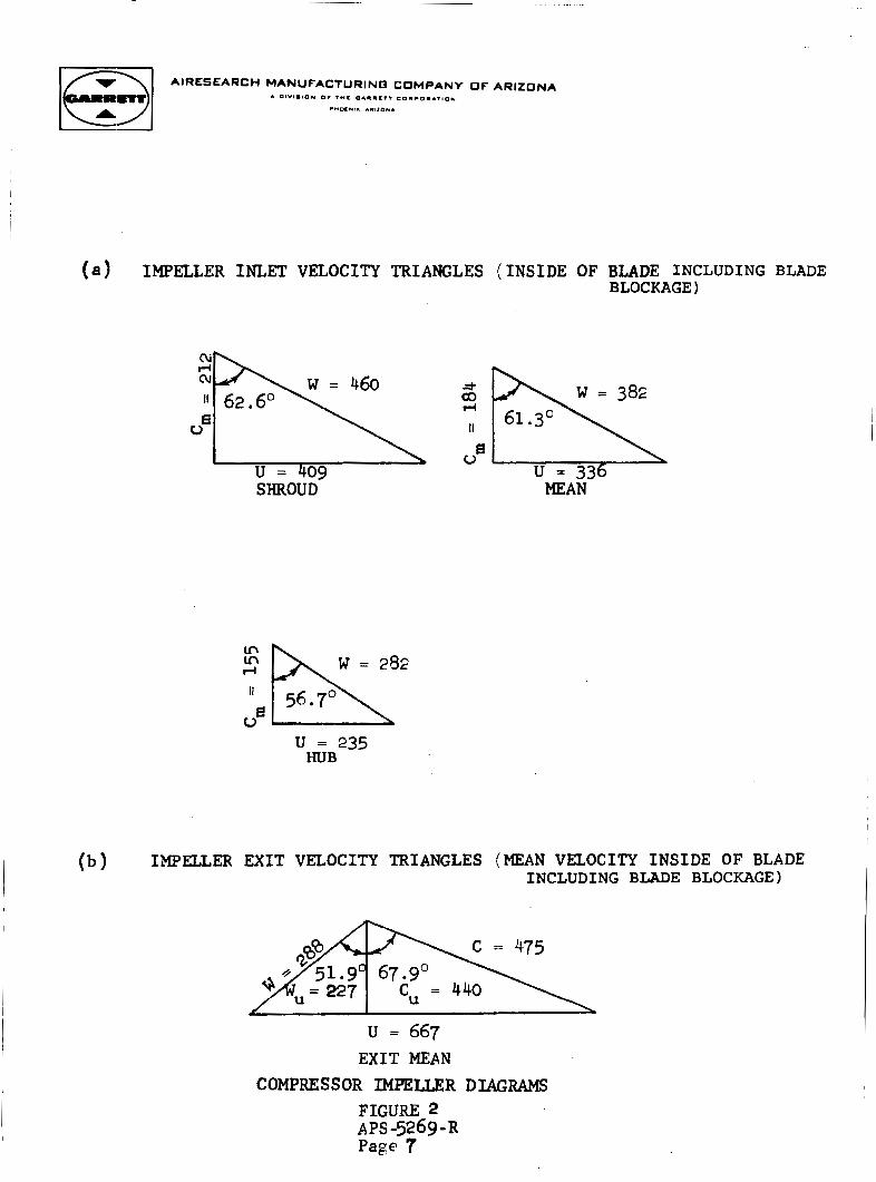
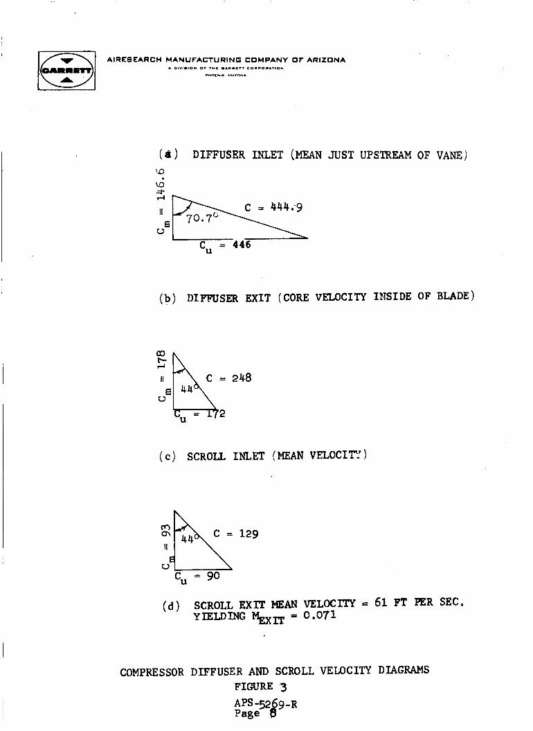
( a ) Velocity vector diagrams. (See Figure 2 f o r impeller ve loc i ty diagrams and Figure 3 fo r d i f f u s e r and s c r o l l ve loc i ty diagrams),
( b ) Ef f ic ienc ies (See Table 1 )
( c ) Pressure r a t i o s T o t a l - t o - t o t a l pressure r a t i o = 1.900 Tota l - to - s t a t i c pressure r a t i o = 1.981
( a ) Actual spec i f i c work = 16.58 hp per l b per sec.
(e) Weight flow = 0.756 lb per sec.
(f) S t a t o r and r o t o r physical dimensions (See Figure 4 )
(8) Tota l and s t a t i c pressures a t i n l e t and e x i t of s t a t o r and r o t o r (See Table 1)
(h) Tota l temperatures a t i n l e t and e x i t (See Table 1 )
AIRLSLARCH MANUFACTURINO COMPANY OF ARIZONA A DIVIW~DU nv m e wAwmm?? cnmcnaAnnn
IO.”,.. “,ID*.
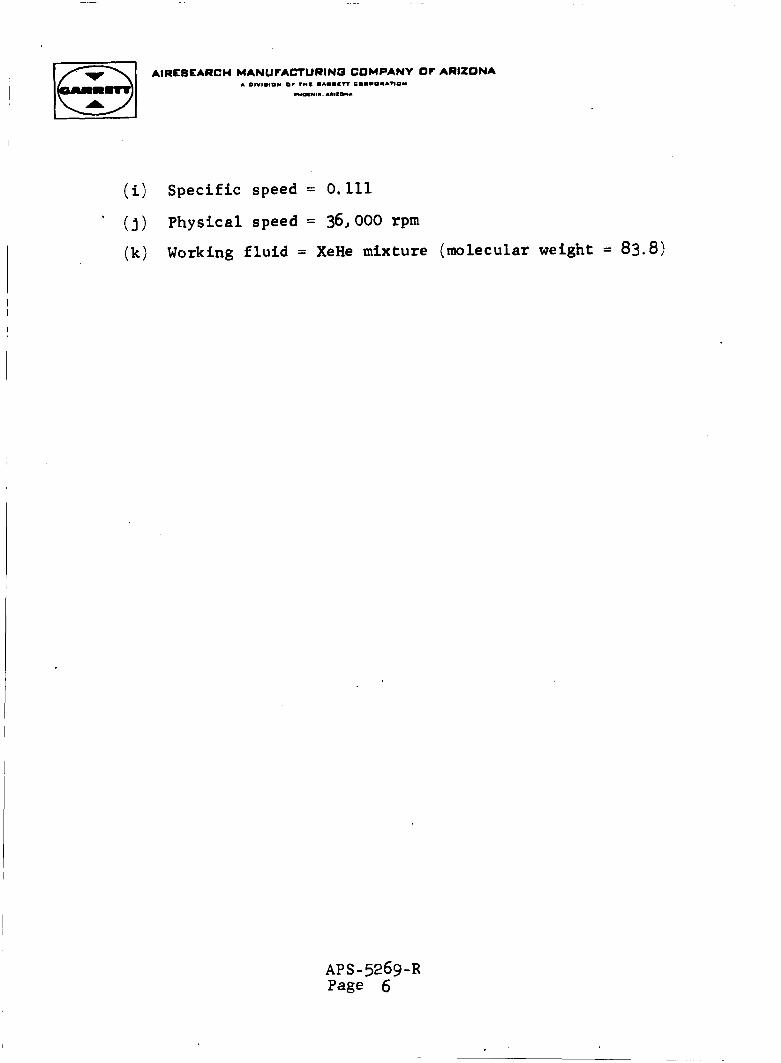
(i) Specif ic speed = 0.111
(j)
( k )
Physical speed = 36,000 rpm
Working f l u i d = XeHe mixture (molecular weight = 83.8)
AP S - 5269 -R Page 6
AIRESEARCH MANUFACTURINB COMPANY OF ARIZONA
( a ) IMPELLER INLET V ~ O C I T Y TRIANGLES (INSIDE OF BLADE INCLUDING BLADE BLOCKAGE)
SHROUD
U = 235 HUB
(b) IMPELLER EXIT VEZOCITY TRIANGLES (MEAN VELOCITY I N S I D E OF BLADE INCLUDING BLADE BLOCKAGE)
c = 475
u = 667 EXIT MEAN
COMPRESSOR IMPELLER DIAGRAMS FIGURE 2
Page 7 APS -5269-R
I
AIRESEARCH MANUFACTURING COMPANY OF ARIZONA
(d ) DIFFUSER INLET (MEAN JUST UPSTREAM OF VANE)
a-
;; 6 u
= 446 cu
(b ) DIFFUSER EXIT (CORE VELOCITY INSIDE OF BLADE)
a3 P-
u
2 48
( C ) SCROLL INLET (MEAN VELOCITY)
m II *A u c, = go 129
(d 1
COMPRESSOR
VELOCITY = 61 FT PER SEC. 0.071
DIFFUSER AND SCROLL VELOCITY DIAGRAMS FIGURE 3
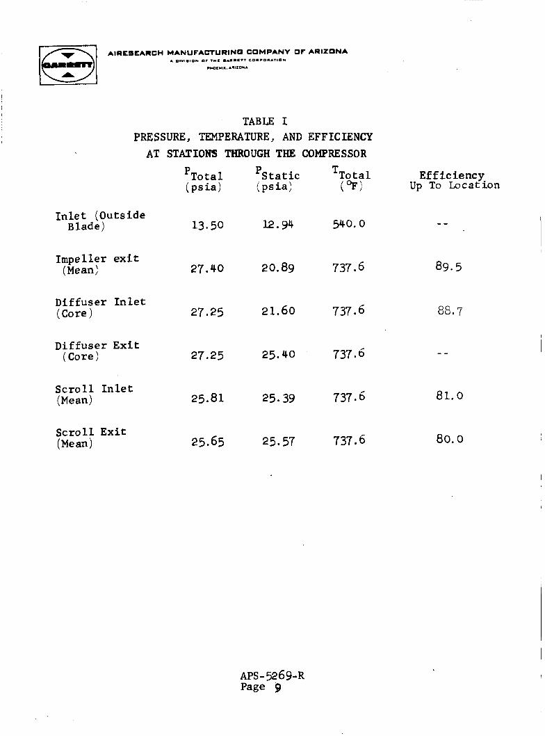
TABLE I PRESSURE, TEMPERATURE, AND EFFICIENCY
AT STATIONS THROUGH THE COMPRESSOR
'Total 'Static TTotal ( ps ia) ( p s i 4 (9)
Efficiency Up To Locat ion
Inlet (Outside Blade) 12.94 540.0 13.50
Impeller exit (Mean) 89.5 20.89 737 6 27.40
Diffuser In le t (Core ) 21.60 737 t5 88.7 27.25
Diffuser Exi t (Core) 737.6 27.25 25.40 - -
Scro l l In le t (Mean) 737.6 81.0 25.81 25.39
Scrol l Exit (Me an) 737 6 80.0 25.65 25.57
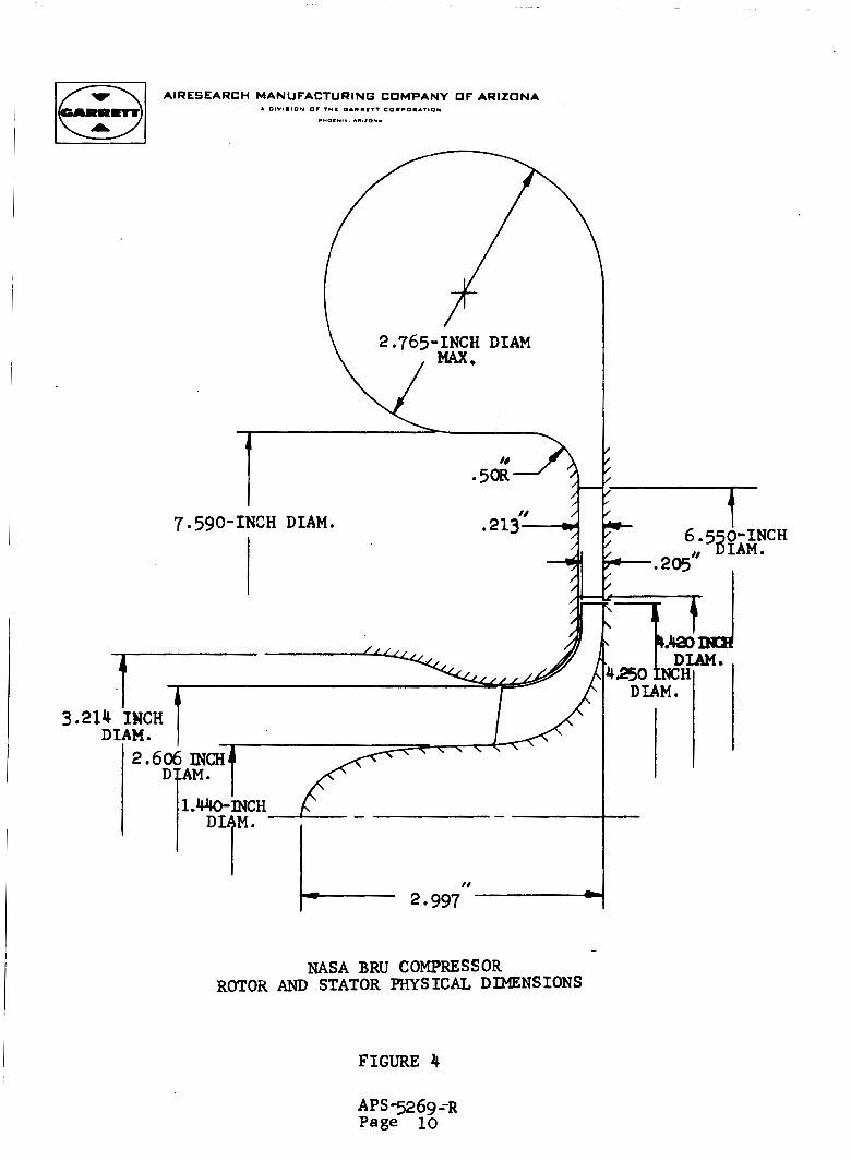
NASA BRU COMPRESSOR ROTOR AND STATOR PHYSICAL DIMENSIONS
FIGURE 4
APS -52 69 --R Page 10
1 x 1 AIRESEARCH MANUFACTURINO COMPANY O F ARIZONA
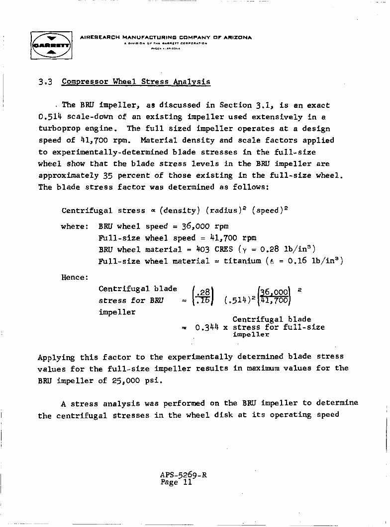
3.3 Compressor Wheel S t r e s s Analysis
- The BRU impeller, a s discussed i n Section 3.1, is an exact 0.514 scale-down of an ex i s t ing impeller used extensively i n a
turboprop engine. The full sized i m p e l l e r operates a t a design speed of 41,700 rpm. Material dens i ty and sca le f a c t o r s applied t o experimentally-determined blade stresses i n t h e f u l l - s i z e wheel show t h a t the blade stress l e v e l s i n the BRU i m p e l l e r are approximately 35 percent of those ex i s t ing in the f u l l - s i z e wheel. The blade stress f a c t o r was determined a s follows:
I
Centrifugal stress = (dens i ty) ( rad ius)* ( s p e e d ) 2
where: BRU wheel speed = 36,000 rpm Full-size wheel speed = 41,700 rpm BRU wheel mater ia l = 403 CRES (y = 0.28 lb/in3) F u l l - s i z e wheel mater ia l = t i tanium ( 6 = 0.16 lb/in")
Hence: Centr i fugal blade stress f o r BRU impeller
Centrifugal blade
irnpe 1 le r = 0.344 x stress f o r f u l l - s i z e
Applying t h i s f a c t o r t o the experimentally determined blade stress va lues f o r t he f u l l - s i z e impel le r results i n maximum values f o r the BRU i m p e l l e r of 25,000 psi.
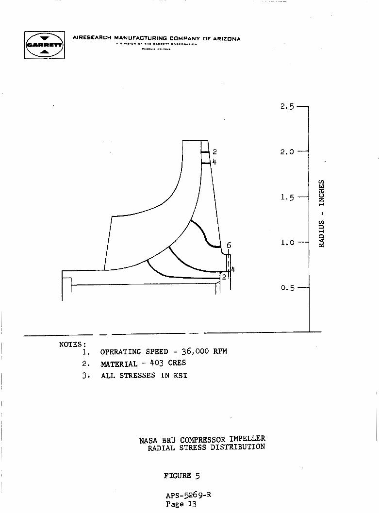
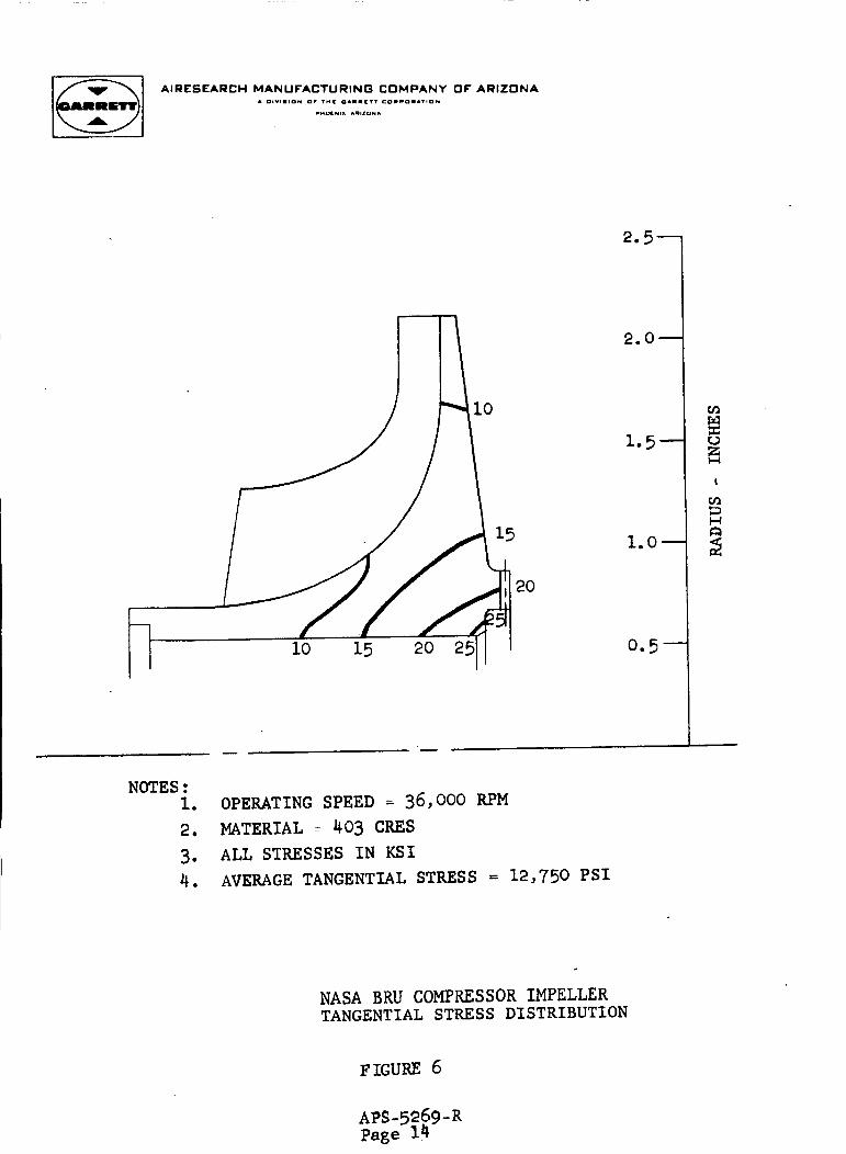
A s t r e s s ana lys i s was performed on the BRU impeller t o determine I t he cen t r i fuga l stresses i n the wheel d i sk at i t s operating speed
A ~ S - 5 2 6 9 - ~ Page 11
of 36,000 rpm. and t a n g e n t i a l stresses expected i n the disk.
Figures 5 8~ 6 present, graphically, the r a d i a l
Yielding of the d i s k may be expected a t a minimum speed of 65,000 rpm and the minimum burst speed may be expected a t 95,000 rpm. negl igable a t the temperatures and stress levels encountered i n this appl ica t ion , t h e BRU compressor wheel may be considered e s s e n t i a l l y an i n f i n i t e - l i f e w h e e l .
Since c reep of the 403 CRES wheel material i s
APS-5269-R Page 12
-1 AIRESEARCH MANUFACTURING COMPANY OF ARIZONA
NOTES : 1. OPERATING SPEED = 36,000 RPM 2. MATERIAL = 403 CRES 3. ALL STRESSES IN KSI
NASA BRU COMPRESSOR IMPELLER RADIAL STRESS DISTRIBUTION
FIGURE 5
AIRESEARCH MANUFACTURING COMPANY OF ARIZONA A OIVI.IO* 0. 7 ° C 0.11171 CO.CD..VIO*
C"OC*ll .91*0*.
2.5-
2.0-
1.5-
1.0-
0.5 -
-
NOTES : 1. 2. MATERIAL = 403 CRES 3. ALL STRESSES I N KSI 4.
OPERATING SPEED = 36,000 RPM
AVERAGE TANGENTIAL STRESS = 12,750 PSI
NASA BRU COMPRESSOR IMPELLER TANGENTIAL STRESS DISTRIBUTION
cn W
Ei I
v1 3 H
9
L
FIGURE 6
APS-5269-R Page 14
3 .4 C r i t ical-Speed Analysis
' In order t o perform a c r i t i ca l - speed analysis f o r the compressor research package, the operating speed range fo r performance t e s t i n g had t o be determined. range f o r t he package is s e t f o r t h i n Table 2 . Selection of the speed range was coordinated w i t h the cognizant personnel a t the NASA-Lewis Research Center.
The desired speed
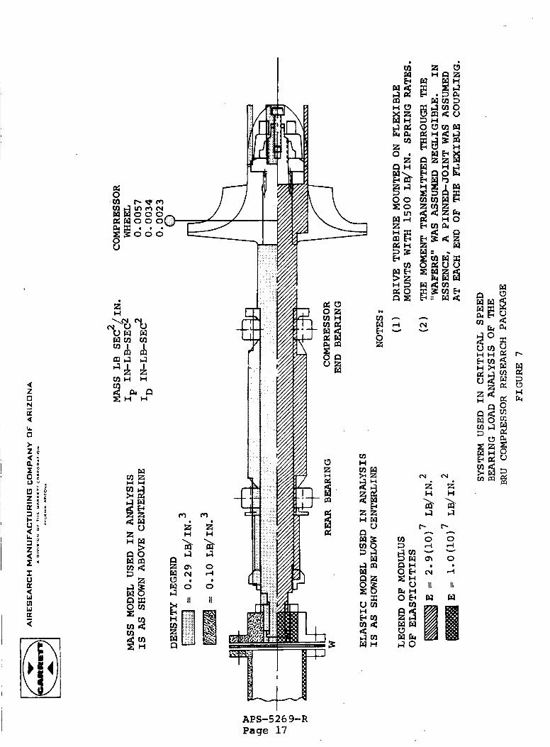
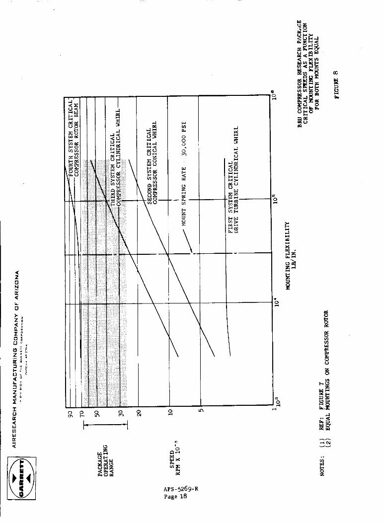
The e l a s t i c and mass model of the ro t a t ing a s s m b l i e s * used in the c r i t i ca l - speed ana lys i s i s shown i n Figure 7
As can be noted, the balanced f l ex ib l e coupling was included i n the e l a s t i c and mass model. I n addi t ion , the Contractor- se lec ted dr ive turbine, t h a t was used for the acceptance t e s t i n g of the research package was included t o determine whether o r not t he f l ex ib l e coupling arrangement wou ld s i g n i - f i c a n t l y influence the rigid-body c r i t i c a l speeds of t h e
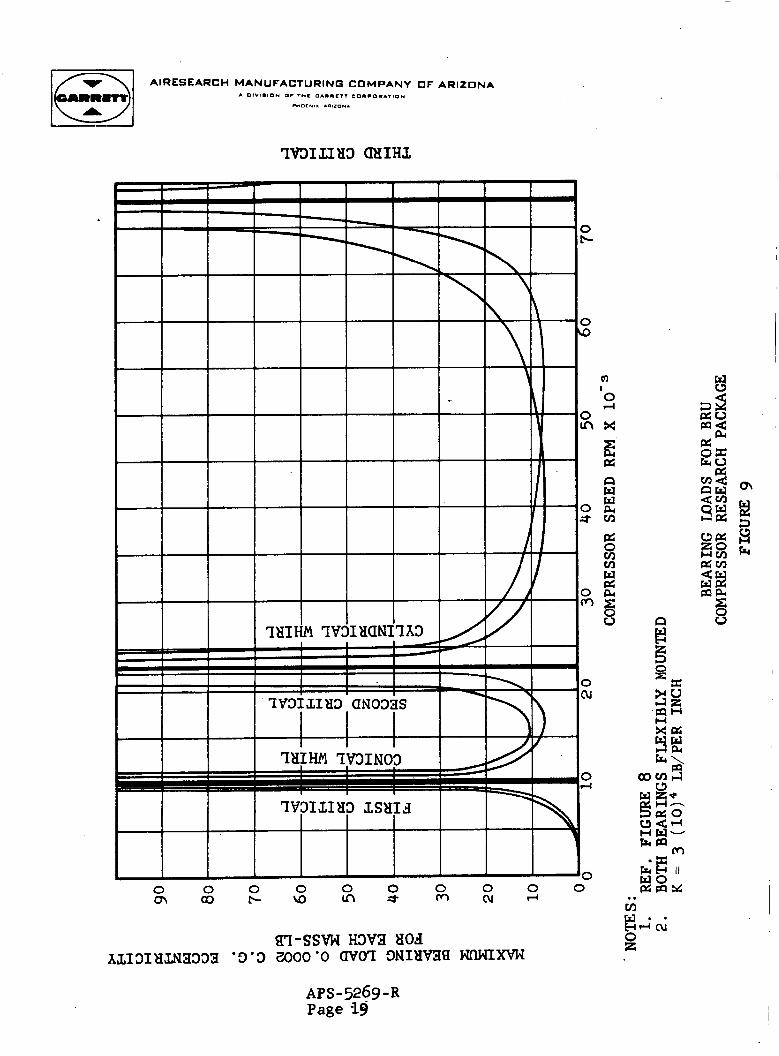
research package. The c r i t i c a l speeds of the compressor package r o t a t i n g assembly, p lo t ted as a function of bearing resi l ient-mount spring r a t e s , a r e shown i n Figure 8 f o r the case of equal spring r a t e mounts a t both bearings. Figure 8 shows that the use of 30,000 ppf r e s i l i e n t mounts a t each bearing w i l l allow t h e corhpressor research package t o operate over the range of 25,550 t o 66,165 rpm without encountering rigid-body c r i t i c a l speeds . The bending mode c r i t i c a l i s shown t o be approximately 74,000 rpm. It should be noted t h a t t he dr ive turb ine system c r i t i c a l speed ( f i r s t s y s t e m c r i t i c a l ) i s very l o w and does not influence the c r i t i c a l speeds of the compressor package. Bearing loads f o r t he an t i c ipa t ed operating range (25,550 to 66,165 rpm) a r e p lo t ted as a function of speed i n Figure 9 f o r an assumed r o t o r c .g . e c c e n t r i c i t y of 0.0002 inch.
APS-5269-R Page 15
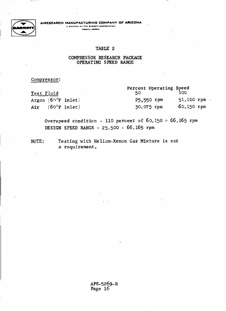
TABLE 2
COMPRESSOR RESEARCH PACKAGE OPERATING SPEED RANGE
Compressor:
Test F l u i d Argon (6Q°F i n l e t ) Air ( 6 0 O ~ i n l e t )
Percent Operating Speed 50 100
25,550 rpm 51,100 rpm 30,075 rpm 60,150 rpm
Overspeed condition - 110 percent of 60,150 = 66,165 rpm DESIGN SPEED RANGE = 25,500 - 66,165 rpm
NOTE : Testing with Helium-Xenon Gas Mixture i s not a requirement.
APS-5269- R Page 16
U 2 0
U U !!!
LL 0
I 0 K a W In
U
' E w
& 0 ii3 r c q c o d l n m r a w 0 0 p s w o o
0 u 3%;
i H
APS-526 9-R Page 17
- - r l c u u w
hl
i H
hl
E c
i ? H O B N f-l
!8 w w W
W
0 ' o\
i
n
APS - 5 2 6 9 - ~ Page 18
ac !4 s 3 a
d 0
d
z 0
AIRESEARCH MANUFACTURING COMPANY OF ARIZONA A DIV I8 ION O r T-C O A I I L I T C O I L O I A T I O N
P*OT* l " .0110*.
1763IL183 mIH3
0 cc
0 0
0
0 I
0 In
0 t
0 m
0 (u
0 PI
0 0 0 0 0 0 0
M cu r( 0 0 0 0 m a3 b \ O I n *
FI
X
E s w W &I cn
n

I I AIRESEARCH MANUFACTURINO COMPANY OF ARIZONA
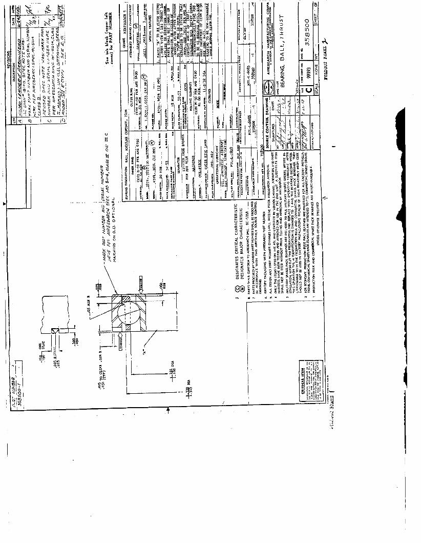
3.5 Bearing and Seal Design Data and Drawings
The angular-contact roll ing-element bearing selected as a r e s u l t of a d i g i t a l computer program optimization f o r the research package shou'ld adequately meet the design object ive of a time-between-over- haul (TBO) of 300 hours minimum when using a i r - o i l m i s t lubr ica t ion (MIL-L-7808). The major c h a r a c t e r i s t i c s of the chosen bearing
, ( P a r t 358500) are :
Bore diameter Outside diameter Width Number of b a l l s Bal l diameter Inner-race curvature
Outer-race curvature
Contact angle Ring and b a l l mater ia l
Separator mater ia l
20 mm 42 mm 12 mm 11 9/32 inch 52 to 53 percent of b a l l diameter 52 t o 53 percent of b a l l diameter 16 degrees Consumable - Electrode vacuum- m e l t e d M-50 t oo l s t e e l I ron-s i l icon- bronze, si lver- plated
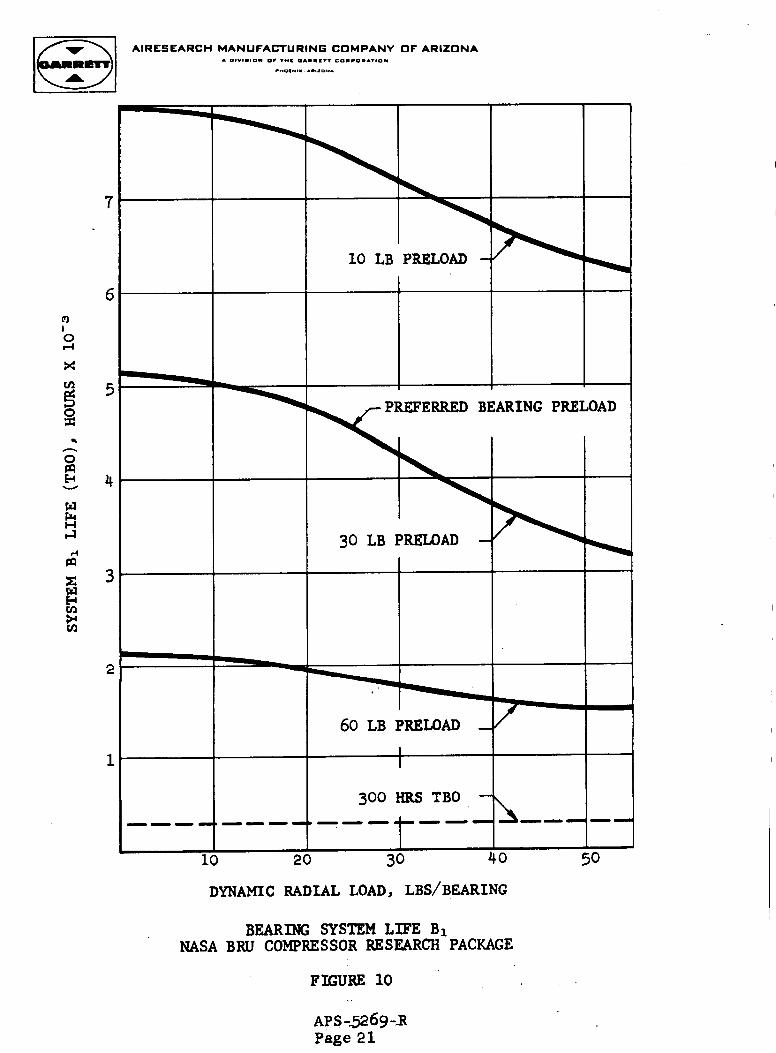
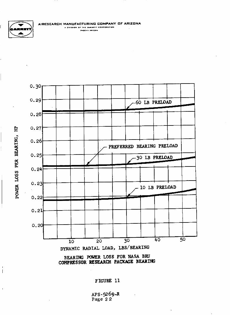
I The un id i r ec t ion (1 "g") r a d i a l bearing loads and t h r u s t loads assumed f o r the ana lys i s a r e shown i n Table 3. The predicted bearing system l i f e , B1, f o r preloads of 10, 30, and 60 pounds f o r the compressor i s shown i n Figure 10. The predicted power l o s s p e r bearing f o r preloads of 10, 30, and 60 pounds f o r the compressor package is plot ted i n Figure 11. Representative package speeds, bearing loads, and predicted system B1 l i f e f o r the package i s presented i n Table 4. It i s evident t h a t the TBO design objec t ive (300 hours minimum) can be e a s i l y m e t . f i g u r a t i o n and mater ia l requirements a re shown in Drawing 358500.
I
I The bearing con-
I APS -5269- R Page 20
AIRESEARCH MANUFACTURING COMPANY OF ARIZONA . 0l"l.IO" or ,"I 0 A m m I r T COICO.AVIO*
C"0.U.. ..L.D*.
- -- . ID
60 LB PRELOAD - I
300 HRS TBO - t-- ---
I I I I
I 20 30 40 50 1
DYNAMIC RADIAL LOAD, LBS/BEARING
BEARING SYSTEM LIFE B1 NASA BRU COMPRESSOR RESEARCH PACKAGE
FIGURE 10
AP S -5269 -R Page 21
AIRESEARCH MANUFACTURING COMPANY OF ARIZONA 1 01v11.10* 01 I"= O.l.ClT colco".IIo*
c(oc*m. .1110*. I
I I I I DYNAMIC RADIAL LOAD, LBS/BEARING
BEARING PWER LOSS FOR NASA BRU CORPRESSOR RE- PACKAGE BEARING
FIGURE 11
AP S - 52 69-14 Page 2 2
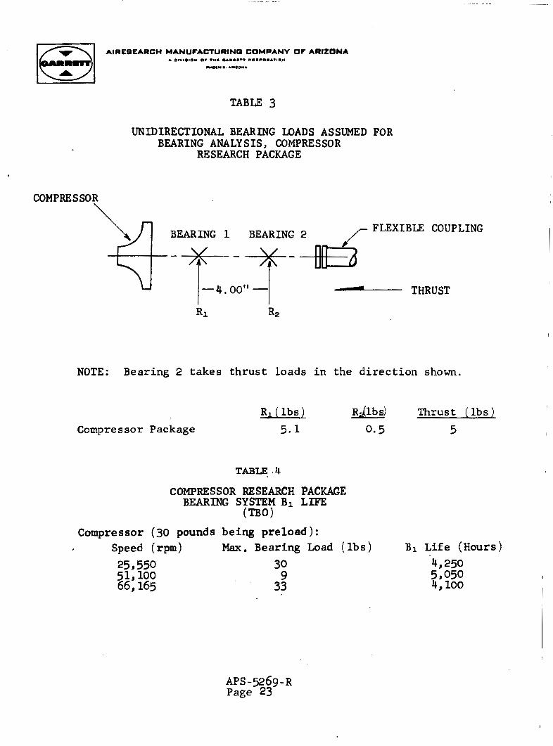
TABLE 3
UNIDIRECTIONAL BEARING LOADS ASSUMED FOR BEARING ANALYSIS, COMPRESSOR
RESEARCH PACKAGE
COMPRESSOR
NOTE: Bearing 2 takes thrust loads i n the direct ion shown.
R 1 ( l b s ) RAlb s) Thrust ( l b s 1 Compressor Package 5 . 1 0.5 5
TABLE .4
COMPRESSOR RESEARCH PACKAGE BEARING SYSTEM B1 LIFE
(TBO) Compressor (30 pounds
Speed (rpm) 253 550 66,165 51,100
being preload ) : Max. Bearing Load ( l b s ) B1 Life (Hours)
30 9
33
A P S - 9 6 9 - R P a g e 23
AIRESEARCH MANUFACTURING COMPANY OF ARIZONA
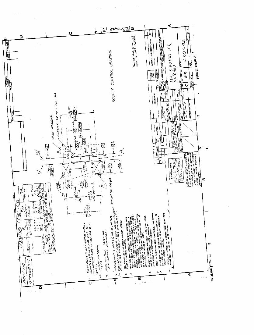
The carbon-face contact s e a l f o r t he compressor i s shown on Drawing 699683. p a r t i c i p a t e i n t h i s program, th ree of whom were selected by the Contractor a s being approved. The s e a l designs proposed by each of the three vendors were qu i t e s imi l a r (standard O-ring configurat ion with wave washer spring loading). i n t e r n a l configurat ion of the s e a l design allows f o r a constant pressure d i f f e r e n t i a l o r d i r e c t i o n of the pressure d i f f e r e n t i a l , The only f ace pressure incurred w i l l r e s u l t from the spring loading and O-ring drag. back-face pressures can be r ead i ly accommodated without s e a l carbon-face leakage o r des t ruc t ion .
Five vendors indicated t h e i r des i r e t o
The
Thus, a very w i d e range of compressor wheel
3 - 6 Compressor Instrumentation
The compressor research package has a full compliment of s t a t i c pressure instrumentation and provisions f o r the addi t ion by the NASA, of t o t a l pressure and temperature instrumentation t o a s s i s t i n the aerodynamic performance evaluat ion of the compressor. The following i s a l i s t of the instrumentation and the provisions therefore as i n s t a l l e d on the compressor research package:
( a ) I n l e t
(1) Three (3) s t a t i c pressure t aps i n the same plane 120' apar t , pipe threads and a 0,030-inch diameter s t a t i c pressure t a p hole.
The bosses a re machined with 1/8-inch
APS -5269-R Page 24
(2) Three (3) basses for t o t a l pressure taps, 0.5-inch down- stream of the s t a t i c pressure taps and ro ta ted 60° t o the s t a t i c taps and 120° apa r t , The bosses a re machined with 1/8-inch threads,
(1) Three ( 3 ) sets of f i v e s t a t i c pressure taps along, the ro to r leading edge sect ion of the r o t o r shroud set 120' apar t .
( 2 ) One (1) set of th ree (3) equally spaced machined bosses located a x i a l l y a t the ro to r t i p f o r blade clearance probes.
( c ) Diffuser
(1) Vaneless sec t ion - Three (3) s t a t i c pressure taps equal ly spaced on the ro to r shroud located between r o t o r o u t l e t and vaned d i f f u s e r i n l e t .
(2) Vaned sec t ion - Two ( 2 ) sets of f i v e (5) s t a t i c pressure t a p s each along the diffuser mid-channel streamline, one (1) set on each side of a diffuser passage.
( d ) Scro l l e x i t
(1) Four ( 4 ) s t a t i c pressure taps i n the same plane, 90' apar t . pipe threads and a 0.030-inch diameter s t a t i c pressure t ap hole.
The bosses a re machined with 1/8-inch
APS-5269-R Page 25
(2) Four ( 4 ) bosses for t o t a l pressure t a p s , 085-inch down- stream of the s t a t i c taps, rotated 4 5 O t o the s t a t i c t a p s
and goo apart. inch p i p e threads.
The bosses are machined with 1/8-
e .
f .
Bearings
(1) Three ( 3 ) C.A. thermocouples on each bearing
Shaft speed
(1) Three (3) Elec tro Products (No. 3016) shaft speed
pickups spaced 45' apart.
APS-5269-R Page 26
4.0 GENERAL UNIT DESCRIPTION
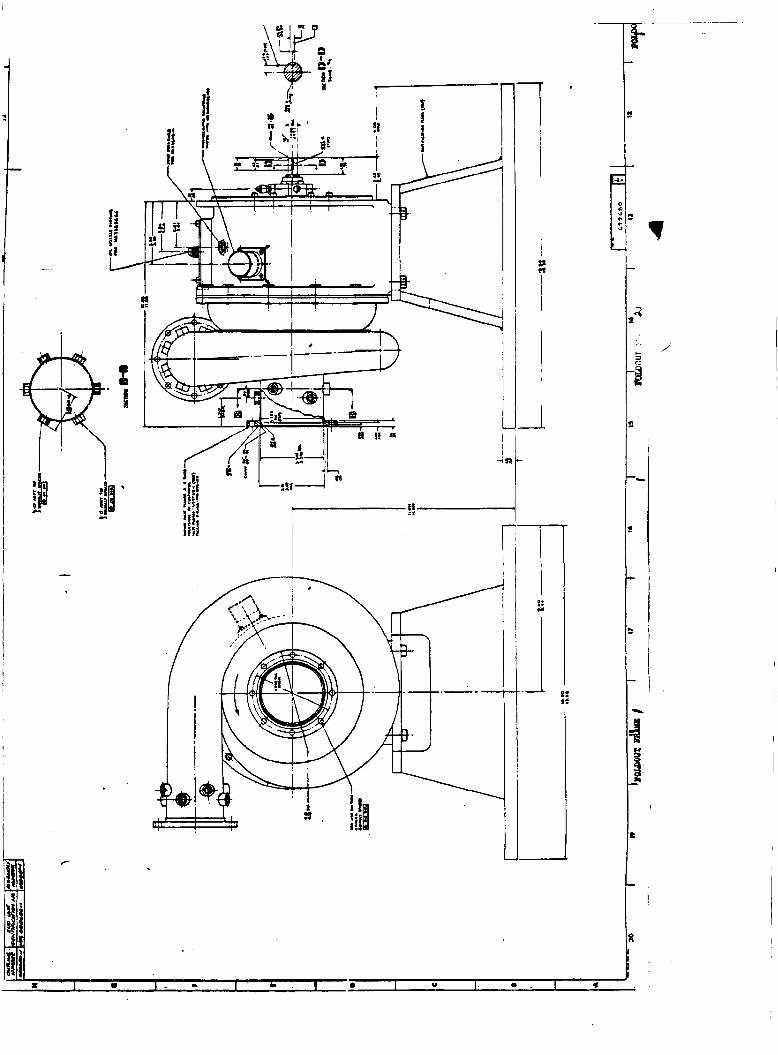
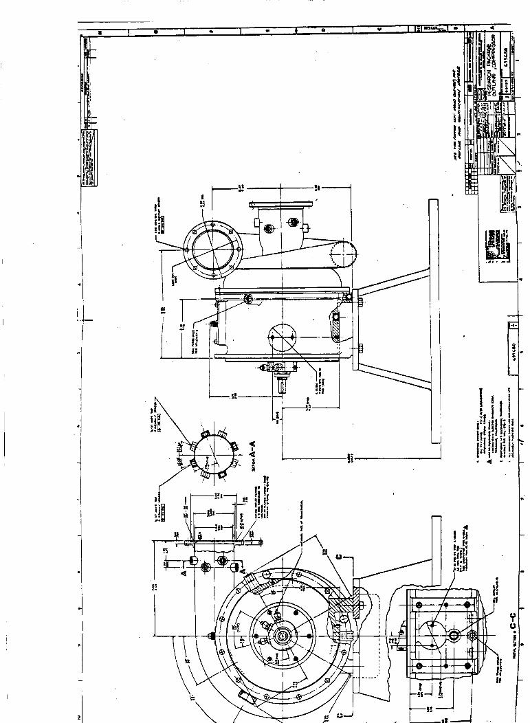
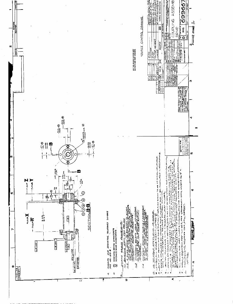
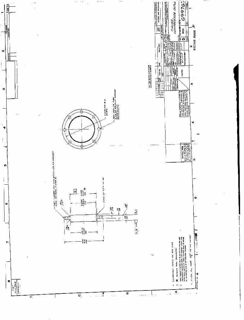
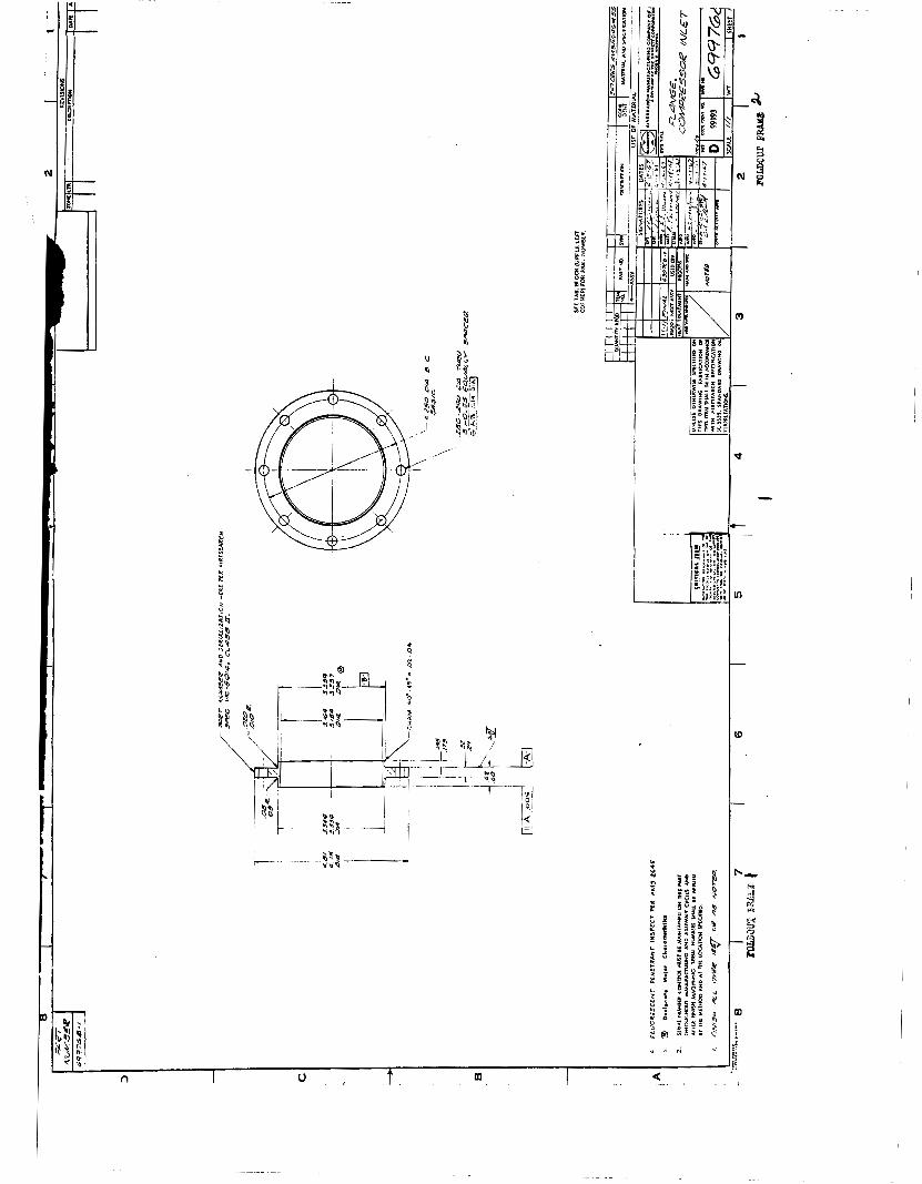
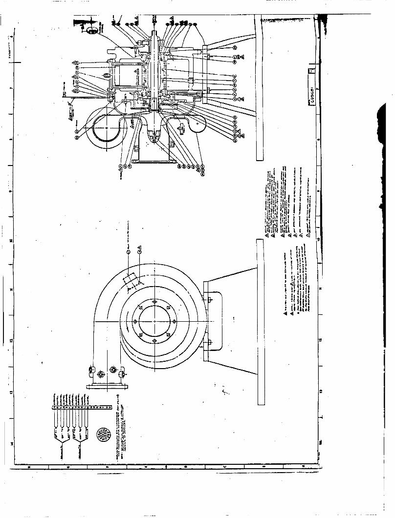
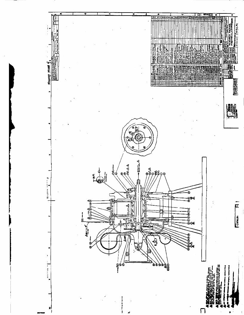
. The dimensional ou t l i ne of the compressor research package is shown i n Drawing 699680. f aces between ( a ) the end of the impeller s h a f t machined t o mate w i t h the d r ive coupling, Drawing 699667 (NASA Drawing CC844330) ( b ) the b o l t f langes a t the compressor i n l e t and discharge t o p e r m i t attachment t o adaptor flanges, Drawings 699767 and 699768 and ( c ) the mating e l e c t r i c a l connectors (temperature, speed and power) and pipe f i t t i n g s . General operating conditions for the u n i t a r e a l s o spec i f ied .
This drawing a l s o d e f i n e s the i n t e r -
A c ross -sec t iona l view of the compressor research package i s shown i n Assembly Drawing (699681). impeller assembly (Item 8) mounted i n the main housing (Item 1) on two a n t i f r i c t i o n bearings (Item 6y a l s o Drawing 358500). Both bearings a r e r e s i l i e n t l y mounted with a s p r i n g r a t e of 30yOO0 pounds p e r inch using the bearing mount assembly (Item 5) . r a t e was chosen so t h a t the operating speed range would be be- tween a low second c r i t i c a l and a ve ry high th i rd c r i t i c a l ; a
coil s p r i n g ( I t e m 30) provides 30 pounds of a x i a l preload on the bearings. An o i l j e t ( I t e m 27) suppl ies pressurized, a i r - o i l mist to each bearing.
The u n i t cons i s t s of the
T h i s spring
Labyrinth type s e a l s a r e provided a t each end of the housing, The impeller end sea l has a purge chamber located i n the middle of the s e a l . The i m p e l l e r end i s a l s o equipped with a carbon-face type oil s e a l ( I t e m 9, a l s o Drawing 699683).
APS-5269-R Page 27
AIRESEARCH MANUFACTURING COMPANY OF ARIZONA
The compressor s c r o l l (I tems 24, 25, and 26) is attached t o the main housing by a bolted flange. the. desired compressor-wheel-shroud-face clearance i s accomplished a t t h i s f lange by providing a shim of predetermined thickness between the housing and the scroll f lange. clearance was es tab l i shed a t 0.007-0.009 inch. Sealing a t t h i s shim is accomplished with the O-rings (NAS 1593-174). A r ig id mounting base (Item 2 ) provides f o r mounting the compressor research package on a test stand bed-plate.
Shimming t o obtain
A design value of the
APS -5269- R Page 28
AIRESEARCH MANUFACTURINO COMPANY OF ARIZONA A OIVI.10N O I 7 ° C . A M M C T t C D M C O M A T I O *
- 0 C N l X . AM11ON1
5.0 COMPRESSOR RESEARCH PACKAGE ACCEPTANCE TESTING
' The compressor research package acceptance tes t was per-
A l l te6t ing was conducted a t the Phoenix formed a t t he AiResearch Manufacturing Company, Phoenix, Arizona on August 15, 1967. Division laboratory f a c i l i t y and was witnessed by a representat ive of the NASA.
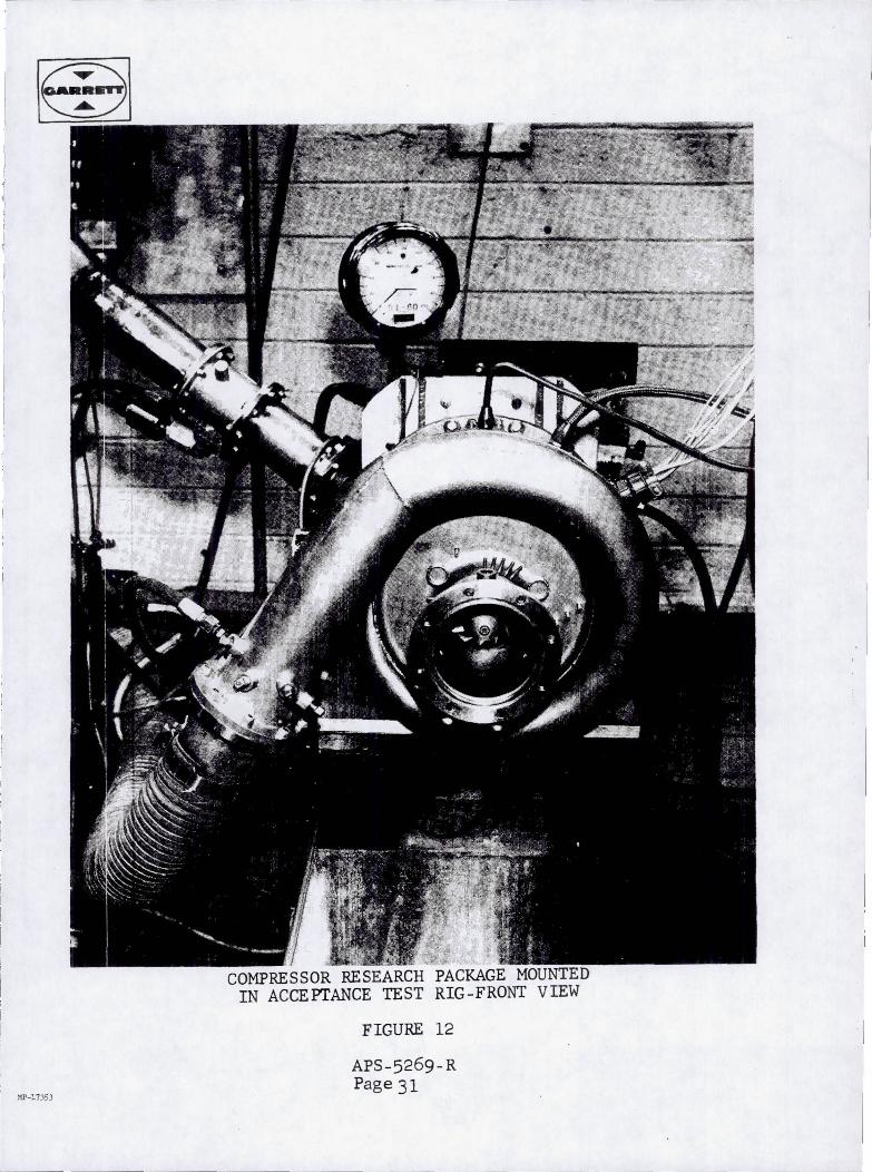
The acceptance test setup consisted of three bas ic components mounted on an aluminum f i x t u r e (see Figures 12, 13, and 1 4 ) a s follows:
( a ) A i h s e a r c h Constant Speed Drive S t a r t e r (CSDS) turbine
( b ) Coupling (NASA Drawing CC844330)
( c ) Compressor Research Package
During the test the CSDS turbine, supplied with p lan t com- pressed a i r energy, was used t o d r ive the compressor package through the 699667 coupling. package w a s furnished by a ca l ib ra t ed Norgren o i l e r .
A i r -o i l m i s t l ub r i ca t ion f o r the
The acceptance tes t was conducted as follows: of the system t o 51,200 rpm (100 percent design speed). system was then s t a b i l i z e d a t design speed f o r the required 30 m i n u t e s , during which t i m e u n i t speed, v ibra t ion , and bearing temperatures were manually recorded a t f ive minute in t e rva l s .
A c r i t i c a l speed The
Following t h i s 30 minute cycle, the speed was increased t o 61,400 rprn (120 percent design speed) f o r 10 minutes. The
APS-5269-R Page 29
~
acceptance test was then complete and the system w a s shut down.
* Acceptance test data, including assembly instructions, parts l i s t , del ivery spares and the unit build history have been delivered t o the NASA Lewis Research Center i n a separate document in accordance with contract requirements.
APS-5269-R Page 30
MP-11J5J
COMPRESSOR RESEARCH PACKAGE MOUNTED IN ACCEPTANCE TEST RIG-FRONT VIEW
FIGURE 12
APS-5269-R Page 31
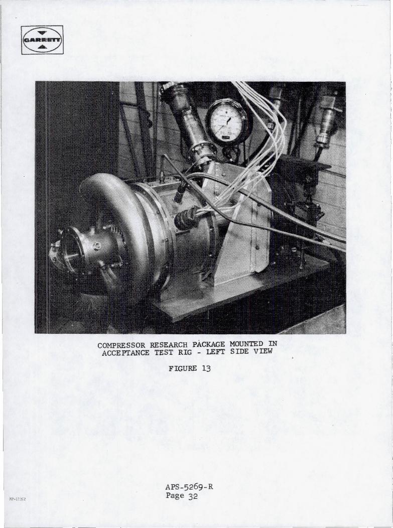
COMPRESSOR RESEARCH PACKAGE MOUNTED IN ACCEPTANCE TEST RIG - LEFT SIDE VIEW
FIGURE 13
APS-5269-R Page 32
---------
I !
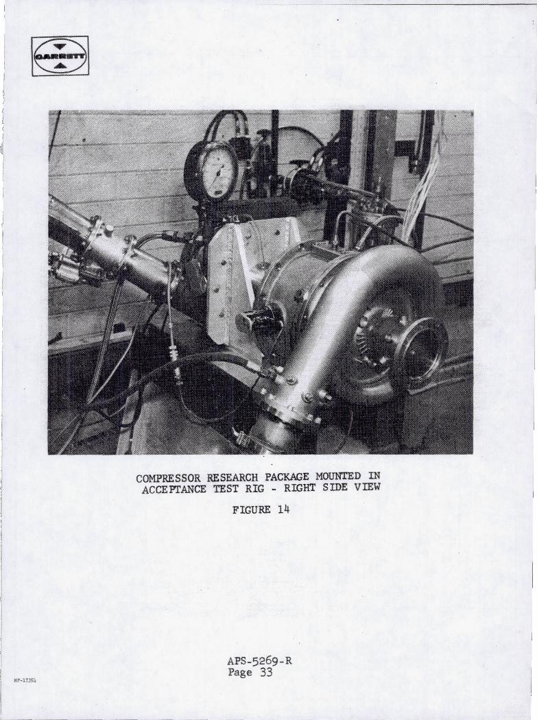
COMPRESSOR RESEARCH PACKAGE MOUNTED IN ACCEPTANCE TEST RIG - RIGHT SIDE VIEW
FIGURE 14
APS-5269-R Page 33
g af
%!
' t L( % n
c I I
.-
.
L
E I I
T I: ,,
9: 1:
.I
I
I
c
GI
I
i V * B E<*_.
..
I
u1
a
I
. . I %.
1
I-
?
L .
U
E3 (li 0
L
9 4. W
Reproduced by N m National Technical Information Service Springfield, VA 221 61
This report was printed speciica/& for your order from nearly 3 million tit/es avai/ab/e in our collection.
For economy and efficiency, NTlS does not maintain stock of its vast collection of technical reports. Rather, most documents are custom reproduced for each order. Documents that are not in. electronic format are reproduced from master archival copies and are the best possible reproductions available. If you have questions concerning this document or any order you have placed with NTIS, please call our Customer Service Department at (703) 605-6050.
About NTlS NTlS collects scientific, technical, engineering, and related business information -then organizes, maintains, and disseminates that information in a variety of formats - including electronic download, online access, CD-ROM, magnetic tape, diskette, multimedia, microfiche and paper.
The NTlS collection of nearly 3 million titles includes reports describing research conducted or sponsored by federal agencies and their contractors; statistical and business information; U.S. military publications; multimedia training products; computer software and electronic databases developed by federal agencies; and technical reports prepared by research organizations worldwide.
For more information about NTIS, call 1-800-553-6847 or 703-605-6000 and request a free copy of the NTlS Catalog, PR-827LPG, or visit the NTlS Website at http://www.ntis.aov.
I
I
Ensuring Permanent, Easy Access to U.S. Government Information Assets
*N6922173*
*BF*
B I N : M2 18-14-83 INVOICE: 1266813 SH I PTO : 1 *85776 PAYMENT : NONE