1.1 history of electric heating - marathon...
TRANSCRIPT
1.1 HISTORY OF ELECTRIC HEATING
Most people consider Thomas Edison as the inventor of electric heater but there is an ambiguity
to it. Some people also believe that Alexander Grahmbell was the man behind the idea of electric
heating. The basic electric heater has been altered very modestly as it is still used the same way.
The electric heater converts electric energy into heat. Electric currents flow through the metal
component which radiates heat in the surrounding area. In 1905, Albert Marsh discovered
chromel. It was the first metallic amalgamation to serve as a heat element and was made of four
parts nickel and one part chromium. This new alloy, called Nichrome was 300 times stronger
than other heat elements founded so far. It created and dispersed heat more efficiently than the
light bulbs in Bell's heater. After Marsh's invention, electric heating began to overtake the sales
of fuel-based heating sources. For this reason, Marsh is called the “father of the electrical heating
industry”. A patent on the development was acquired in 1906.
1.2 BENEFITS OF ELECTRIC HEATING
1.2.1 ECONOMIC ADVANTAGES
It is a frequent delusion that electric heating is pricey to run. Although other forms of fossil fuels
are cheaper to buy than electricity, but, when on the whole running costs are analyzed, electric
heating is a feasible substitute.
Lifecycle Costs
This is one of the foremost things to be considered, when comparing the fiscal impact of heating
technologies. Among the many factors, the energy cost and the operating costs (including the
depreciation costs) over the life span of the equipment are the most important. Electric heaters
are 100% efficient at the point of use, i.e. all the electricity used is converted directly into heat,
unlike fuel based systems where energy is wasted through flue. Also this kind of heating has
virtually no moving parts; most systems can be expected to last for at least 15 years. But, it might
be obligatory to compute the lifetime cost of the complete line including all its investment,
production, and maintenance factors to make a reasonable assessment.
Low capital & installation costs
Electric heating is very easy to install, thereby installation costs are minimum. It simply requires
a connection to the electrical circuit, so it can frequently be installed in a short span of time. As
the heaters can work as stand-alone units or as a system, it is easy and cheap to add heaters to a
system at anytime as budgets permit.
Initial Investment
In addition to lifecycle costs, another economic argument, the initial investment cost of the
installation is to be kept in mind while making a decision. Except for dielectric heating, other
electro-heat technologies usually have an upper hand on this point. In several cases, this will
prove to be a major motive to prefer electro-heat technologies over heating techniques
employing fossil fuel.
Electricity pricing Tariffs
In many applications heating is preferred principally during night. The availability of low-cost
base-load electricity during low load periods of the day, such as night time is, by default,
exceptionally favorable in such cases. Also, larger electricity consumers may gain from
discounted special rates based on average annual load demand.
Depleting resources
An environmental cum economic argument in support of all electro-heat technologies is that
electricity prices are less volatile than the prices of fossil fuels or natural gas. Natural gas is a
diminishing energy source and its price will rise substantially greater before the last reserves are
cracked. The Energy Return on Energy Investment (EROEI) is a fine gauge for evaluating the
economic viability of an energy source. Trending nowadays, the EROEIs of both oil and natural
gas are in sheer decline, showing that most accessible treasures have already been used. This
implies that even without considering environmental issues into the big picture, we will be
enforced to budge to a non-fossil-fuel economy at some point in the forthcoming decades.
Safe & Reliable Systems
Safety is always an important consideration in any process. Because no fuel is burnt internally to
generate heat, they are protected from associated safety risks, such as carbon monoxide
poisoning or explosions. Also, there is less risk of damage to system, as there are no leakages or
radiators. With virtually no moving parts to break down or wear out, electric heating is
exceptionally reliable and will usually run adequately for a much longer period.
1.2.2 LOGISTIC ADVANTAGES
Accessible technologies
Low initial investment cost owing to the high power density of electro heat technologies in
addition to compact installations are a major leap in this area. Another fact is that there are no
storage issues and fuel transport involved, as with some fossil fuels. These rewards coalesce to
make electro-heat technologies much more accessible and hence popular among SMEs,
especially in the food and metal processing industries.
Suitable for control and automation
The output of electro-heat equipment can be easily adapted to the ambient conditions and the
target material by regulating parameters such as voltage and current. This makes them highly
sensitive to errors and suitable for fully automated production. Thanks to PID controllers, SSR
and SCR (thyristor) controllers, the installations can be turned on and off at high speed. Fossil
fuel heaters are much trickier to control, often being limited to simple on-off control with a
consequential loss of efficiency.
Conversion efficiency of electric heating
100% efficiency is a major milestone that promotes electric heating and is unaffected by running
at less than full load. Although, fossil fuel heaters achieve maximum efficiencies in the range of
80% but when the heater is not running at full load or is subjected to cycling on-off, efficiencies
can drop to as low as 5%. This should be kept in mind when comparing the running costs of
electric heating with other fuel types.
1.2.3 ENVIRONMENTAL ADVANTAGES
Electro-heat techniques exhibit considerably better results than fossil fuel heating systems in
terms of CO2 emissions, transmission and distribution losses taken into account. Water
vapour is another by-product of combustion in fossil fuel heating, so this is a problem in
cases where dehumidification is necessary. Electric heaters produce no fumes or water
vapour, thereby eliminating the need for supplementary ventilation or dehumidification.
1.3 ELECTRO-HEAT TECHNOLOGIES
Mentioned below are the most practiced industrial electric process heating (electro-heating)
technologies:
1. Direct Resistance Heating: The most commonly used heating technology; it operates by
passing electric current directly through an electrically-conductive object to directly heat
it by Joule heat utilizing the internal resistance of object. Direct Resistance Heating
technology enables rapid heating of materials, thereby contributing to size reduction of
heating equipment, improved heating efficiency, a clean work environment and simple
operation. Due to these features, it is preferred over fuel based heating.
2. Indirect Resistance Heating: An electric current is driven through a resistor, which
heats up, and through convection and radiation, heats up a surrounding fluid or gas. Its
energy efficiency is rather poor, but can still be cost-effective by making use of special
electricity tariffs and by optimizing the geometrical position. Advantages include a
consistent product quality (essential in the food and drinks industry) and uniform energy
supply over the volume (essential in metallurgy). It leads to an exact production capacity,
consistent production quality, uniform energy supply over the volume and a high degree
of modularity.
3. Infrared or Radiant Heating: This is a widely employed heating technique in which a
heat source at high temperature emits infrared waves that are subsequently absorbed by a
colder object. Commonly used for surface treatments (heating or drying) and pre-heating
purposes, it is also frequently used in the food industry for baking and in the metallurgy
and textile industries for fixing coatings and drying paint. Its major benefits include low
investment cost of the installation and high power density, ensuing in very compact
installations with a high heating rate.
4. Arc Heating: This method is ideal for creating very high temperatures. An electric arc
drawn between two electrodes has a temperature between 3000 to 35000C depending on
the electrode material, so is employed in arc furnaces for melting of metals and also for
arc welding. Electric arc furnaces are also used in stone wool manufacturing, production
of inorganic chemicals, reduction and pre-reduction of non-ferrous metals, and
production of high-carbon ferro-alloys.
5. Direct Induction Heating: Currents are induced by electromagnetic action in the body to
be heated and produce a sufficiently high temperature to melt the metal. This is mainly
used as a melting technique for non-ferrous alloys. Direct induction heating is inherently
more efficient than fuel heating and infrared for heating metal strips.
6. Indirect Induction Heating: A solenoid generates an alternating magnetic field. If a
conductor is placed inside this field, an alternating electric current, called eddy current, is
induced in this conductor that opposes the alternating magnetic field. These eddy currents
heat up the conductor. The heat so produced is transmitted to the body to be heated by
radiation and convection, as in the indirect-resistance method.
7. Dielectric Heating: When a changing electrical field is applied to an electrical insulating
material with an asymmetrical molecule structure, friction will occur between the
vibrating molecules as they attempt to align with this field, leading to internal heat
development. In spite of its low energy efficiency, it will often be the most energy
efficient option for materials with low thermal conductivity, such as rubber and certain
plastics. This technology is particularly common in food industry.
Among the different electro-heat technologies mentioned above, resistive heating is the simplest,
efficient and useful technology as it based on an uncomplicated OHM’S LAW. Its applications
include agro-food, petrochemicals, fine chemicals, pharmaceuticals, packaging industries,
machine tool, and ovens, baking ovens (vault and / or sole), bath, fryers, stove and many more.
1.4 RESISTIVE HEATING
An electric current flowing through a material that has some resistance (except a
superconductor) creates heat. This resistive heating corresponds to the work done by the
charge carriers in order to travel to a lower potential.
Electric heaters consist of a conductor whose resistance is selected so as to generate the
requisite amount of resistive heating.
There are two simple formulas for calculating the resistance of a conductor and amount of heat
dissipated in a resistor. This heat is measured in terms of power i.e. energy per unit time. Thus
we are calculating the rate at which energy is being converted into heat inside a conductor.
The first formula for calculating the resistance is:
V = I x R
Where V is the voltage, I is the current through the resistor and R is the value of the resistor.
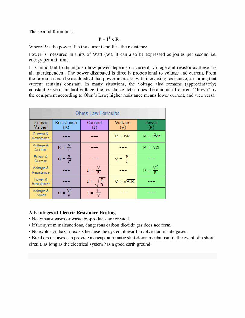
The second formula is:
P = I2 x R
Where P is the power, I is the current and R is the resistance.
Power is measured in units of Watt (W). It can also be expressed as joules per second i.e.
energy per unit time.
It is important to distinguish how power depends on current, voltage and resistor as these are
all interdependent. The power dissipated is directly proportional to voltage and current. From
the formula it can be established that power increases with increasing resistance, assuming that
current remains constant. In many situations, the voltage also remains (approximately)
constant. Given standard voltage, the resistance determines the amount of current “drawn” by
the equipment according to Ohm’s Law; higher resistance means lower current, and vice versa.
Advantages of Electric Resistance Heating
• No exhaust gases or waste by-products are created.
• If the system malfunctions, dangerous carbon dioxide gas does not form.
• No explosion hazard exists because the system doesn’t involve flammable gases.
• Breakers or fuses can provide a cheap, automatic shut-down mechanism in the event of a short
circuit, as long as the electrical system has a good earth ground.
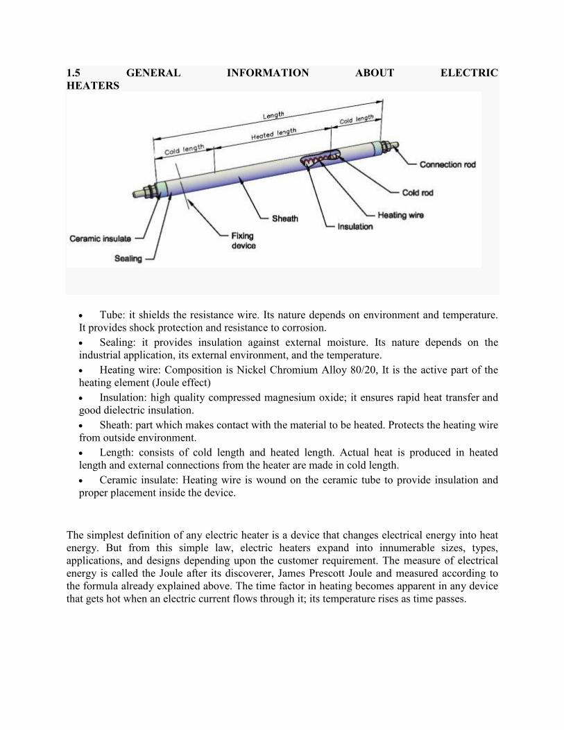
1.5 GENERAL INFORMATION ABOUT ELECTRIC
HEATERS
• Tube: it shields the resistance wire. Its nature depends on environment and temperature.
It provides shock protection and resistance to corrosion.
• Sealing: it provides insulation against external moisture. Its nature depends on the
industrial application, its external environment, and the temperature.
• Heating wire: Composition is Nickel Chromium Alloy 80/20, It is the active part of the
heating element (Joule effect)
• Insulation: high quality compressed magnesium oxide; it ensures rapid heat transfer and
good dielectric insulation.
• Sheath: part which makes contact with the material to be heated. Protects the heating wire
from outside environment.
• Length: consists of cold length and heated length. Actual heat is produced in heated
length and external connections from the heater are made in cold length.
• Ceramic insulate: Heating wire is wound on the ceramic tube to provide insulation and
proper placement inside the device.
The simplest definition of any electric heater is a device that changes electrical energy into heat
energy. But from this simple law, electric heaters expand into innumerable sizes, types,
applications, and designs depending upon the customer requirement. The measure of electrical
energy is called the Joule after its discoverer, James Prescott Joule and measured according to
the formula already explained above. The time factor in heating becomes apparent in any device
that gets hot when an electric current flows through it; its temperature rises as time passes.
1.6 METHODS FOR DETERMINING HEATER REQUIREMENTS
Following steps need to be taken for determining the requirements of heater for any application:
1. Define the Heating Problem
o Gather application information
o Sketch problem for visual reference
2. Calculate Power Requirements
o System start-up power requirement
o System maintenance power requirements
o Operating heat losses
3. System Application Factors
o Operating temperature
o Operating efficiency
o Safe/permissible watt densities
o Mechanical considerations
o Operating environment factors
o Heater life requirements
o Electrical lead considerations
o Safety factor
4. Select Heater
o Type
o Size
o Quantity
5. Select Control System
o Type of temperature sensor and location
o Type of temperature controller
o Type of power controller
1.7 COMMON KNOW HOW FOR HEATERS
1.7.1 TRANSFER OF HEAT
When a body starts to generate heat, i.e. its temperature rises above that of other nearby objects;
it is called a heat source. As its temperature increases, it starts to raise the temperature of the
materials in its surrounding area using any combination of three different methods. These three
methods are conduction, convection, and radiation.
Conduction transfers heat energy from one material to another via direct contact. It is a direct
method of transferring heat energy, and is usually the most efficient: the highest percentage of
heat energy created transfers to the colder object from the heat source.
Convection also uses physical contact to transfer heat energy, but the contact entails the use of an
agent gas, typically air. In this kind of heating, the heat source warms the gas. The warmed gas
now has less density, so it rises, creating convection currents that move the heated gas into
contact with the colder objects, warming them. The left cooled gas flows back to the heat source
where it is warmed again, and the process repeats.
Radiation does not rely on any physical contact between the heat source and the object to be
heated. Instead, heat energy is transmitted through space from the heat source to the object in the
form of electromagnetic radiation. One example is infrared wavelengths.
1.7.2 TEMPERATURE MEASURING SCALES
Three temperature measuring scales (Fahrenheit, Celsius, Kelvin) are widely used today.
Fahrenheit The earliest established temperature scale using Mercury invented by
Gabriel Fahrenheit in 1970 and named after him. The zero degrees
were established by using a mixture of Ice water and salt.
Celsius Historically called centigrade, in the honor of the founder, Anders
Celsius. An SI derived unit, accepted by most countries. The melting
point of ice and boiling point of water are the two benchmarks of this
unit.
Kelvin Established as the standard for thermometry, Lord Kelvin developed
a universal thermodynamic scale based on the temperature at which
all thermal motion ceases in the classical description of
thermodynamics.
For conversion from Fahrenheit to Celsius use the formula:
C = (F - 32) * 5/9
For conversion from Kelvin to Celsius use the formula:
C = K - 273.15
1.7.3 ALLOYS FOR HEATING ELEMENT
Materials for electric heating depend upon an inherent resistance to the flow of electricity to
generate heat. Copper wire does not get hot when carrying electricity because it has good
electrical conductivity. Thus for an alloy to perform as an electric heating element, it must resist
the flow of electricity. The property to resist the flow of electricity is called as resistivity. Along
with resistivity, other properties are also essential for the alloy to work as heating element. One
such property is that the alloy should have endurance capability to sustain the heat produced i.e.
it should have good life.
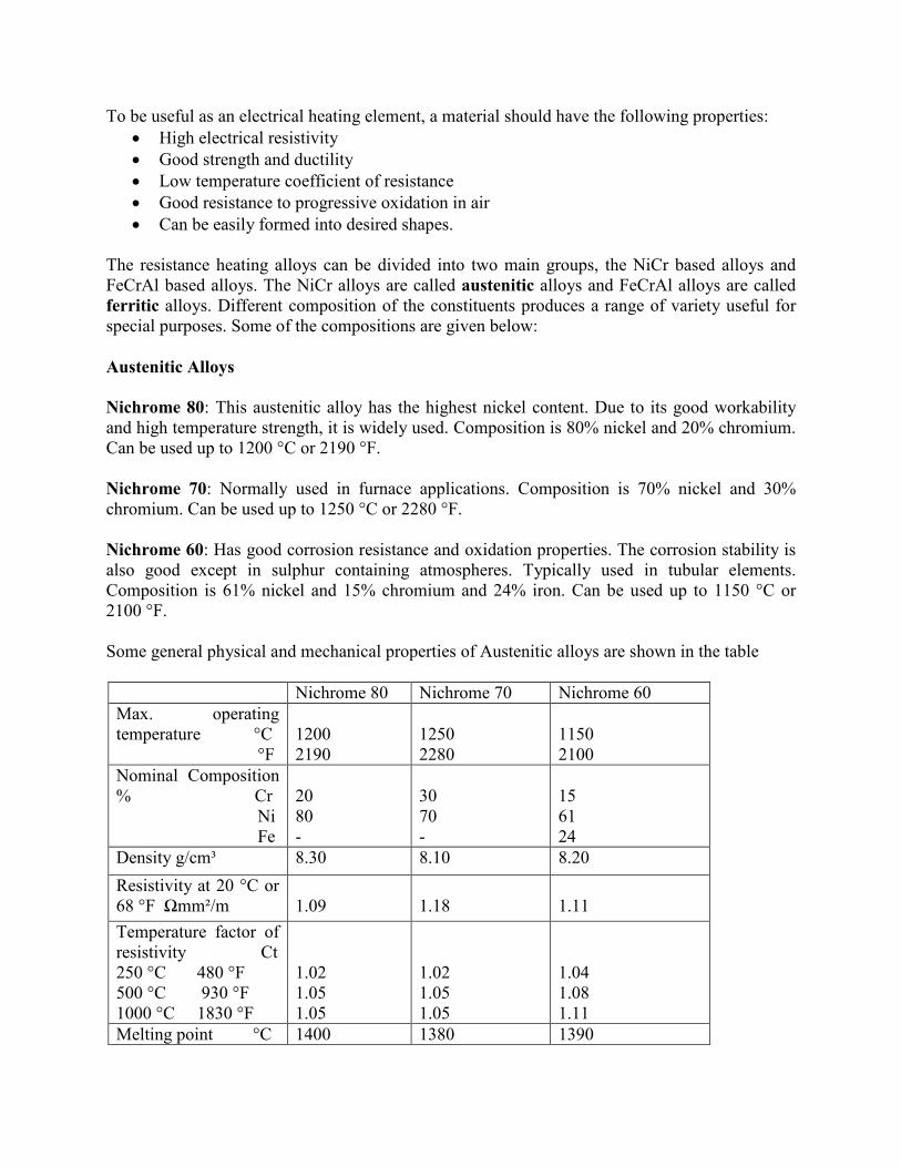
To be useful as an electrical heating element, a material should have the following properties:
• High electrical resistivity
• Good strength and ductility
• Low temperature coefficient of resistance
• Good resistance to progressive oxidation in air
• Can be easily formed into desired shapes.
The resistance heating alloys can be divided into two main groups, the NiCr based alloys and
FeCrAl based alloys. The NiCr alloys are called austenitic alloys and FeCrAl alloys are called
ferritic alloys. Different composition of the constituents produces a range of variety useful for
special purposes. Some of the compositions are given below:
Austenitic Alloys
Nichrome 80: This austenitic alloy has the highest nickel content. Due to its good workability
and high temperature strength, it is widely used. Composition is 80% nickel and 20% chromium.
Can be used up to 1200 °C or 2190 °F.
Nichrome 70: Normally used in furnace applications. Composition is 70% nickel and 30%
chromium. Can be used up to 1250 °C or 2280 °F.
Nichrome 60: Has good corrosion resistance and oxidation properties. The corrosion stability is
also good except in sulphur containing atmospheres. Typically used in tubular elements.
Composition is 61% nickel and 15% chromium and 24% iron. Can be used up to 1150 °C or
2100 °F.
Some general physical and mechanical properties of Austenitic alloys are shown in the table
Nichrome 80 Nichrome 70 Nichrome 60
Max. operating
temperature °C
°F
1200
2190
1250
2280
1150
2100
Nominal Composition
% Cr
Ni
Fe
20
80
-
30
70
-
15
61
24
Density g/cm³ 8.30 8.10 8.20
Resistivity at 20 °C or
68 °F Ωmm²/m
1.09
1.18
1.11
Temperature factor of
resistivity Ct
250 °C 480 °F
500 °C 930 °F
1000 °C 1830 °F
1.02
1.05
1.05
1.02
1.05
1.05
1.04
1.08
1.11
Melting point °C 1400 1380 1390
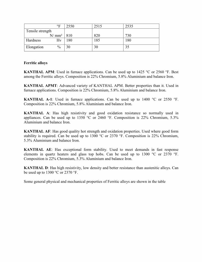
°F 2550 2515 2535
Tensile strength
N/ mm²
810
820
730
Hardness Hv 180 185 180
Elongation % 30 30 35
Ferritic alloys
KANTHAL APM: Used in furnace applications. Can be used up to 1425 °C or 2560 °F. Best
among the Ferritic alloys. Composition is 22% Chromium, 5.8% Aluminium and balance Iron.
KANTHAL APMT: Advanced variety of KANTHAL APM. Better properties than it. Used in
furnace applications. Composition is 22% Chromium, 5.8% Aluminium and balance Iron.
KANTHAL A-1: Used in furnace applications. Can be used up to 1400 °C or 2550 °F.
Composition is 22% Chromium, 5.8% Aluminium and balance Iron.
KANTHAL A: Has high resistivity and good oxidation resistance so normally used in
appliances. Can be used up to 1350 °C or 2460 °F. Composition is 22% Chromium, 5.3%
Aluminium and balance Iron.
KANTHAL AF: Has good quality hot strength and oxidation properties. Used where good form
stability is required. Can be used up to 1300 °C or 2370 °F. Composition is 22% Chromium,
5.3% Aluminium and balance Iron.
KANTHAL AE: Has exceptional form stability. Used to meet demands in fast response
elements in quartz heaters and glass top hobs. Can be used up to 1300 °C or 2370 °F.
Composition is 22% Chromium, 5.3% Aluminium and balance Iron.
KANTHAL D: Has high resistivity, low density and better resistance than austenitic alloys. Can
be used up to 1300 °C or 2370 °F.
Some general physical and mechanical properties of Ferritic alloys are shown in the table
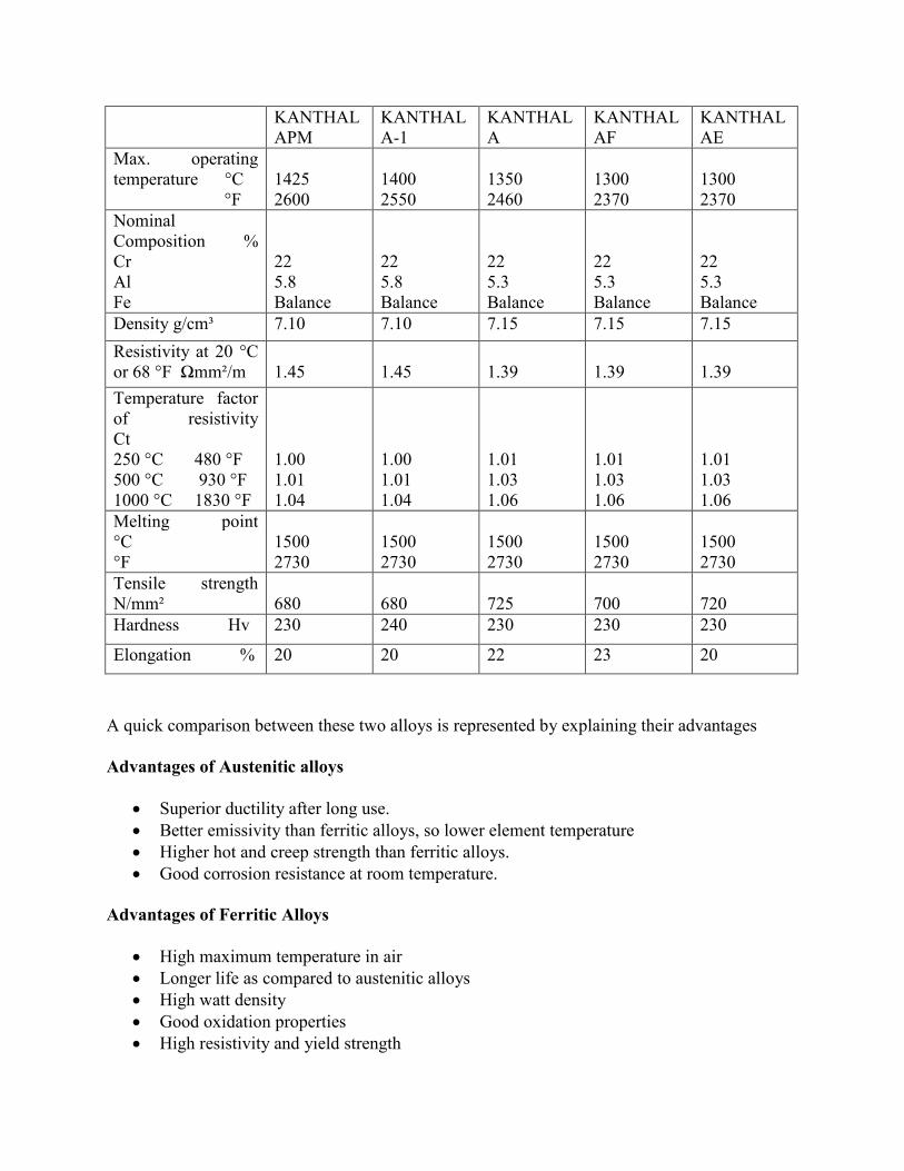
KANTHAL
APM
KANTHAL
A-1
KANTHAL
A
KANTHAL
AF
KANTHAL
AE
Max. operating
temperature °C
°F
1425
2600
1400
2550
1350
2460
1300
2370
1300
2370
Nominal
Composition %
Cr
Al
Fe
22
5.8
Balance
22
5.8
Balance
22
5.3
Balance
22
5.3
Balance
22
5.3
Balance
Density g/cm³ 7.10 7.10 7.15 7.15 7.15
Resistivity at 20 °C
or 68 °F Ωmm²/m
1.45
1.45
1.39
1.39
1.39
Temperature factor
of resistivity
Ct
250 °C 480 °F
500 °C 930 °F
1000 °C 1830 °F
1.00
1.01
1.04
1.00
1.01
1.04
1.01
1.03
1.06
1.01
1.03
1.06
1.01
1.03
1.06
Melting point
°C
°F
1500
2730
1500
2730
1500
2730
1500
2730
1500
2730
Tensile strength
N/mm²
680
680
725
700
720
Hardness Hv 230 240 230 230 230
Elongation % 20 20 22 23 20
A quick comparison between these two alloys is represented by explaining their advantages
Advantages of Austenitic alloys
• Superior ductility after long use.
• Better emissivity than ferritic alloys, so lower element temperature
• Higher hot and creep strength than ferritic alloys.
• Good corrosion resistance at room temperature.
Advantages of Ferritic Alloys
• High maximum temperature in air
• Longer life as compared to austenitic alloys
• High watt density
• Good oxidation properties
• High resistivity and yield strength
• Lower density than austenitic alloys.
Alloys for heating element are chosen according to the properties it possesses so as to build a
nearly ideal heater. Other alloys can also be used as heating elements but these two are the most
popular and widely used. Austenitic alloys can be molded in the form of wire or strip for using it
as a heating element. Ferritic alloys can be formed in wire, strip, tube or bar depending on the
application.
The life of a resistance heating alloy depends on a number of factors such as temperature,
temperature cycling, contamination, alloy composition, trace elements and impurities, wire
diameter, surface condition, atmosphere, mechanical stress etc.
Alloy Selection
There are some important design factors which contribute to the choice of the alloy. Some of
them are discussed below:
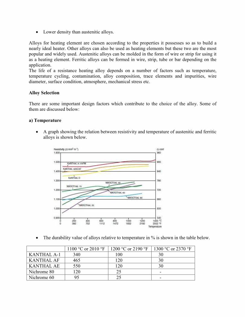
a) Temperature
• A graph showing the relation between resistivity and temperature of austenitic and ferritic
alloys is shown below.
• The durability value of alloys relative to temperature in % is shown in the table below.
1100 °C or 2010 °F 1200 °C or 2190 °F 1300 °C or 2370 °F
KANTHAL A-1 340 100 30
KANTHAL AF 465 120 30
KANTHAL AE 550 120 30
Nichrome 80 120 25 -
Nichrome 60 95 25 -
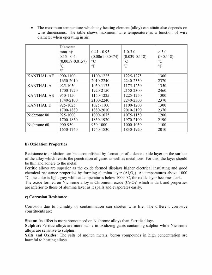
• The maximum temperature which any heating element (alloy) can attain also depends on
wire dimensions. The table shows maximum wire temperature as a function of wire
diameter when operating in air.
Diameter
mm(in):
0.15 - 0.4
(0.0059-0.0157)
°C
°F
0.41 - 0.95
(0.0061-0.0374)
°C
°F
1.0-3.0
(0.039-0.118)
°C
°F
> 3.0
(> 0.118)
°C
°F
KANTHAL AF 900-1100
1650-2010
1100-1225
2010-2240
1225-1275
2240-2330
1300
2370
KANTHAL A 925-1050
1700-1920
1050-1175
1920-2150
1175-1250
2150-2300
1350
2460
KANTHAL AE 950-1150
1740-2100
1150-1225
2100-2240
1225-1250
2240-2300
1300
2370
KANTHAL D 925-1025
1700-1880
1025-1100
1880-2010
1100-1200
2010-2190
1300
2370
Nichrome 80 925-1000
1700-1830
1000-1075
1830-1970
1075-1150
1970-2100
1200
2190
Nichrome 60 900-950
1650-1740
950-1000
1740-1830
1000-1050
1830-1920
1100
2010
b) Oxidation Properties
Resistance to oxidation can be accomplished by formation of a dense oxide layer on the surface
of the alloy which resists the penetration of gases as well as metal ions. For this, the layer should
be thin and adhere to the metal.
Ferritic alloys are superior as the oxide formed displays higher electrical insulating and good
chemical resistance properties by forming alumina layer (Al2O3). At temperatures above 1000
°C, the color is light grey while at temperatures below 1000 °C, the oxide layer becomes dark.
The oxide formed on Nichrome alloy is Chromium oxide (Cr2O3) which is dark and properties
are inferior to those of alumina layer as it spalls and evaporates easily.
c) Corrosion Resistance
Corrosion due to humidity or contamination can shorten wire life. The different corrosive
constituents are:
Steam: Its effect is more pronounced on Nichrome alloys than Ferritic alloys.
Sulphur: Ferritic alloys are more stable in oxidizing gases containing sulphur while Nichrome
alloys are sensitive to sulphur.
Salts and Oxides: The salts of molten metals, boron compounds in high concentration are
harmful to heating alloys.
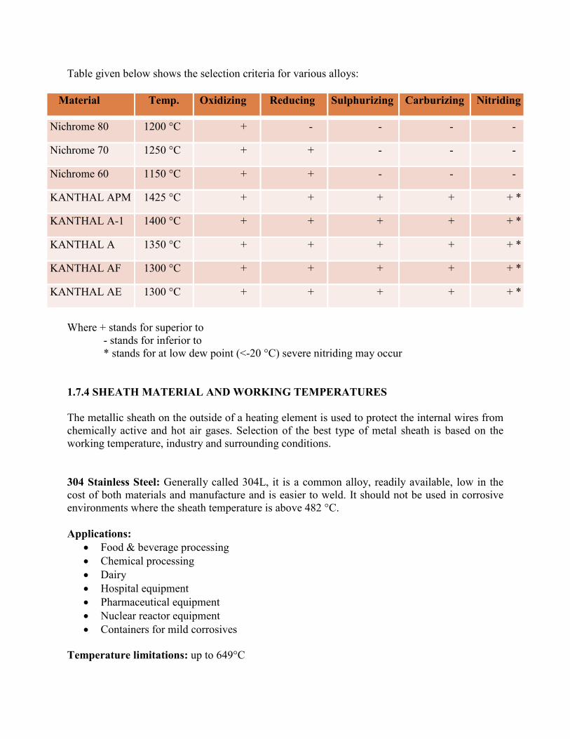
Table given below shows the selection criteria for various alloys:
Material Temp. Oxidizing Reducing Sulphurizing Carburizing Nitriding
Nichrome 80 1200 °C + - - - -
Nichrome 70 1250 °C + + - - -
Nichrome 60 1150 °C + + - - -
KANTHAL APM 1425 °C + + + + + *
KANTHAL A-1 1400 °C + + + + + *
KANTHAL A 1350 °C + + + + + *
KANTHAL AF 1300 °C + + + + + *
KANTHAL AE 1300 °C + + + + + *
Where + stands for superior to
- stands for inferior to
* stands for at low dew point (<-20 °C) severe nitriding may occur
1.7.4 SHEATH MATERIAL AND WORKING TEMPERATURES
The metallic sheath on the outside of a heating element is used to protect the internal wires from
chemically active and hot air gases. Selection of the best type of metal sheath is based on the
working temperature, industry and surrounding conditions.
304 Stainless Steel: Generally called 304L, it is a common alloy, readily available, low in the
cost of both materials and manufacture and is easier to weld. It should not be used in corrosive
environments where the sheath temperature is above 482 °C.
Applications:
• Food & beverage processing
• Chemical processing
• Dairy
• Hospital equipment
• Pharmaceutical equipment
• Nuclear reactor equipment
• Containers for mild corrosives
Temperature limitations: up to 649°C
Inconel: It is a nickel- chromium alloy and is more expensive than most stainless steels. It is
suitable for prolonged use at high temperatures and resists corrosion by simple acids and very
pure water. Inconel is also gaining popularity as a water heating element.
Applications:
• Furnace components
• Chemical & food processing
• Nuclear power generation
• Caustic chemicals
• Air and radiant heating
Temperature limitations: up to 1149°C
310 Stainless Steel: This is commonly used at higher temperatures because it is stronger and
resists air attack better. Also better corrosion resistance in fossil fuel gases.
Applications:
• Air heaters
• Baking equipment
• Chemical processing equipment
• Furnace parts
• Heat exchangers and electric
• Petroleum refining
Temperature limitations: up to 1038 °C
316 (& 316L) Stainless Steel: Better corrosion resistance to most chemicals, salts, acids and
good resistance to sulphur.
Applications:
• Marine trim exteriors
• Chemical and food processing
• Petroleum refining equipment
• Pharmaceutical equipment
• Paper & pulp
• Textile finishing
Temperature limitations: up to 871°C
Hastelloy-X: This alloy is expensive due to the addition of iron, chromium and molybdenum. It
has excellent high temperature strength and good oxidation resistance.
Applications:
• Gas Turbines for power generation
• Aerospace applications
• Industrial furnaces
• Boiler & pressure vessels
Temperature limitations: up to 1177°C
1.7.5 HEAT REQUIREMENT CALCULATIONS
There are two basic heat energy requirements in the sizing of heaters for a particular application.
Start up Heat is the heat energy required to bring a process up to operating temperature. Start-
up heat requirement calculations consists of three basic equations. These three different
equations are referred to as Equations A, B, or C: the wattage needed to heat a material to a
specific temperature in a given amount of time (Equation A); the wattage needed to overcome
the losses at operating temperature (Equation B); and a special calculation needed to reach a
melting or vaporizing point (Equation C.)
Equation A calculates the amount of wattage (W) needed to raise the temperature of a material
to a specific amount in °F (∆F) in a given number of hours (T), weight of the material being
heated and its specific heat value (c) being known:
Formula A: Wattage required for heat-up =
Weight of material x Specific Heat x Temperature Rise °F
3.412 x Heat up Time
Equation B calculates the amount of wattage (W) needed to maintain the temperature of a
material based upon its known wattage loss per square foot (WL/SF) multiplied by the area (A)
in square feet:
Formula B: Wattage losses at operating temperature = Wattage loss/sq.ft. x Area in sq.ft.
The final equation, Equation C, determines the additional wattage necessary for melting or
vaporizing a material. Whenever a material changes state, from a solid to liquid, or liquid to gas,
it requires an additional energy to initiate the change. The heat needed to melt a solid material is
known as the latent heat of fusion (Hf) while the latent heat of vaporization (Hv) determines the
energy needed to change a substance from a liquid to a vapor. The equation for both is identical,
with the value of Hf or Hv substituted as necessary for the value H:
Formula C: Wattage for melting or vaporizing =
Weight of material x Heat of fusion or vaporization
3.412 x Heat-up time
Operating Heat is the heat energy required to maintain the desired operating temperature
through normal work cycles. When calculating the required kW, the maximum flow of the
medium to be heated, the minimum temperature at the heater inlet and the maximum desired
outlet temperature are used.
Once the volume of airflow (CFM – in cubic feet per minute) and the required temperature rise
(∆T – in degrees F) through the heater are known, the required kilowatt rating (KW) of the heater
can be determined from the formula:
KW = Volume of air flow (CFM) x temperature rise (F)
3193
OR
KW = Volume of air flow (Liters/Sec) x temperature rise (C)
837
The larger of the start-up heat and operating heat values, will be the wattage required for the
application.
1.7.6 WATT DENSITY
Watt density is the rated wattage of the heater divided by the overall area being heated. Watt
density (watts per square inch of heater surface area) determines heater operating temperature for
a given set of conditions. The watt density depends on how efficiently the material being heated
distributes its heat throughout its volume. For example, metals, light oils and water have high
heat distribution rates that permit the use of high watt densities. While syrups, heavy oils and
hydraulic fluids with low heat distribution need lower watt densities to prevent spot overheating.
This can lead to damage of the heating element and even the heated material.
Safe values of watt density vary with operating temperature, flow velocity, and heat transfer
rates. Higher the material temperature, lower the watt density should be, especially those
materials which coke or carbonize, such as oils. Watt densities should be low if a material is
being heated to a temperature near the change of state, such as water to steam at 212°F.
Watt Density Calculations
Watt density = Rated wattage of the heater
Total Area x Heated Length
Safe values of watt densities vary with operating temperature, flow velocity, and heat transfer
rates. If the watt density is too high, the elements may burn out or accelerated attack on sheath
elements may take place. If the watt density is too low the heater price will be high. The greatest
heater life will come from the lowest watt density practical for the application.
In general, watt density is determined by three factors:
a) Maximum outlet temperature
b) Type of fluid heated and
c) Fluid flow rate
Maximum watt densities are based on heated length, and may vary depending upon
concentration of some solutions.
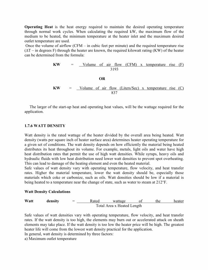
1.7.7 WIRING PRACTICES IN HEATERS
Where VP: Phase Voltage
VL: Line Voltage
IP: Phase Current
IL: Line Current
W: Wattage
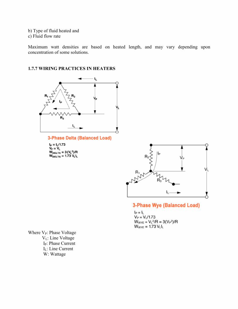
1.7.8 CALCULATING CURRENT REQUIREMENT
On a single phase (two-wire) power supply, the amperage per line is calculated by:
1 Ph Current = Total Wattage / Line Voltage
On three phase power circuits with balanced Delta or Wye heating loads, line current is
calculated by:
3 Ph Current = Total Wattage / Line Voltage x 1.73
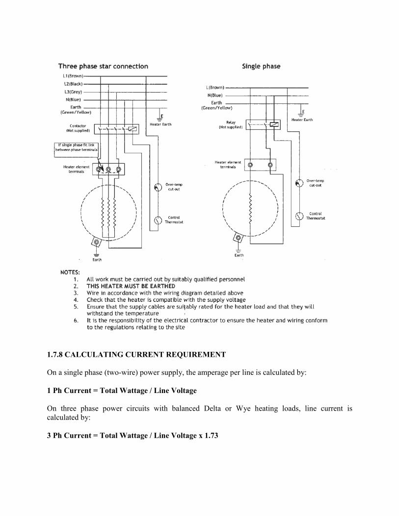
1.7.9 QUICK METHODS OF CALCULATING POWER REQUIREMENTS
The following formula will give a quick estimate of the power required in each application.
For Heating Steels:
For Heating Oils:
For Heating Water in Tanks:
For Heating Air:
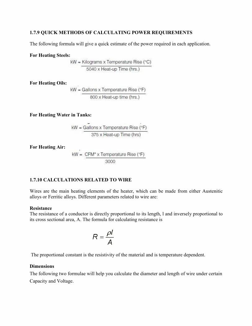
1.7.10 CALCULATIONS RELATED TO WIRE
Wires are the main heating elements of the heater, which can be made from either Austenitic
alloys or Ferritic alloys. Different parameters related to wire are:
Resistance The resistance of a conductor is directly proportional to its length, l and inversely proportional to
its cross sectional area, A. The formula for calculating resistance is
The proportional constant is the resistivity of the material and is temperature dependent.
Dimensions
The following two formulae will help you calculate the diameter and length of wire under certain
Capacity and Voltage.
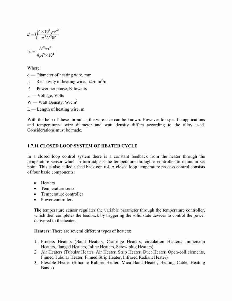
Where:
d — Diameter of heating wire, mm
p — Resistivity of heating wire,Ω·mm2/m
P — Power per phase, Kilowatts
U — Voltage, Volts
W — Watt Density, W/cm2
L — Length of heating wire, m
With the help of these formulas, the wire size can be known. However for specific applications
and temperatures, wire diameter and watt density differs according to the alloy used.
Considerations must be made.
1.7.11 CLOSED LOOP SYSTEM OF HEATER CYCLE
In a closed loop control system there is a constant feedback from the heater through the
temperature sensor which in turn adjusts the temperature through a controller to maintain set
point. This is also called a feed back control. A closed loop temperature process control consists
of four basic components:
• Heaters
• Temperature sensor
• Temperature controller
• Power controllers
The temperature sensor regulates the variable parameter through the temperature controller,
which then completes the feedback by triggering the solid state devices to control the power
delivered to the heater.
Heaters: There are several different types of heaters:
1. Process Heaters (Band Heaters, Cartridge Heaters, circulation Heaters, Immersion
Heaters, flanged Heaters, Inline Heaters, Screw plug Heaters)
2. Air Heaters (Tubular Heater, Air Heater, Strip Heater, Duct Heater, Open-coil elements,
Finned Tubular Heater, Finned Strip Heater, Infrared Radiant Heater)
3. Flexible Heater (Silicone Rubber Heater, Mica Band Heater, Heating Cable, Heating
Bands)
Temperature Sensor: They can be classified as:
1. Contact Temperature Sensors such as Thermocouples, RTD’s and Thermistor
2. Non Contact Temperature Sensors such as Pyrometer.
Temperature Controller: Temperature controller also comes in a range of configurations.
The main groups are:
1. Thermostats
2. PID Controller (Microprocessor based)
Power Controllers
1. Solid State Relay System
2. SCR Controlling System
3. Integrated Control Panel System
Temperature Sensors: All temperature sensors work on the same principle; all of them run on
the same basic principle that they give temperature in the output according to the changes
produced in their physical characteristics in the input.
1. Contact Temperature Sensors: The sensors remain in contact with the body whose
temperature is to be measured. In industrial and laboratory processes, the measurement
point is usually far from the indicating instrument. So it senses the temperature in terms
of electrical quantities like voltage, resistance etc. Majorly, they are of three types:
a) Thermocouples: They are amongst the easiest temperature sensors used in
science and industry and are very cost effective. Comprising of a thermo element
(junction of two dissimilar metals), it operates on the basis of the junction located
in the process producing a small voltage, which increases with temperature.
b) Resistance Temperature Detector (RTD): It utilizes a precision resistor, the
resistance (Ohms) value of which increases with temperature. RTD has a positive
temperature coefficient. Such variations are very stable and precisely repeatable.
c) Thermistors: Thermistor is a semiconductor used as a temperature sensor. It
displays a very distinct non linear resistance versus temperature relationship. The
resistance of thermistor decreases with increase in temperature; called as negative
temperature coefficient. It exhibits a very large resistance change, for small
temperature changes. High sensitivity and small size makes them ideal for use in
medical equipment.
2. Non Contact Temperature Sensors: When the sensors used are inaccurate, too slow, or
difficult to use, non contact temperature sensors are the perfect choice because they
measure a target’s temperature without contact. Sensors are not allowed to remain in
contact with the body whose temperature is to be measured. Most common type is
Pyrometer. Property of emission of heated objects is used as the principle in these
sensors. Every object whose temperature is above absolute zero emits radiation. The
wavelength/frequency of these heat radiations depends on temperature. The radiations are
captured by detecting devices and transformed into electric signals.
Temperature Controllers: A temperature controller produces an output action based on the
input signal received from a sensor. Controllers used in heating applications are called
reverse acting. Depending on the controller, output actions can control a heating device.
Temperature controllers are either thermostats (on/off control) or PID controllers.
Thermostat (On/Off Control): Thermostat is a component which senses the temperature of the
system and regulates it so that the system's temperature is maintained near a desired value. It
does this by switching the heaters on or off. Sensors are used in thermostat to measure the
temperature and output controls the heater. The output tends to high or low when the temperature
crosses the predefined point. This constant on/off around the set point will lower life cycle of
heater, increase thermal losses and oxidation rate of heating elements. To overcome this
problem, a power controlling device can be used in conjunction with the thermostat or a PID
controller can be used. This not only maximizes the heater performance but also adds a
hysteresis to minimize stress on the heater and avoid contactor damage.
PID (Proportional-Integral-Derivative) Temperature Control: Such type of controllers is
used for optimum thermal system performance. It senses the rate of temperature increase or
decrease and adjusts the output action accordingly. As per its name, it provides a proportional
control or a proportional combined integral and derivative temperature control. Proportioning
means operating heat closer to the set point, hence less power requirement. This can be done by
using derivative and integral operating modes. The controller comes in all sizes; inputs to it have
to be decided prior, output action requires a power controller to withstand rapid switching cycles.
Most PID controllers come with four different control functions for different applications.
• P control only
• PI control (no offset= higher overshoot)
• PD control (steady state in shortest time)
• PID control. It combines the advantages of PI and PD control. Also called fuzzy logic
control.
Power Controllers: Power controllers receive input from the temperature controller and apply
or interrupt the electric power to the heating element. Power controllers switch electric
power through solid state devices.
Solid state devices use semiconductors, which can be electronically switched ON or OFF thereby
giving precise power control. The advantages include almost infinite life and ability to deliver
the rapid switching cycles required by PID temperature controller. Common solid state power
controllers are SSRs (solid state relays) and SCRs (silicon controlled rectifiers).
Solid State Relay (SSR): A solid state relay (SSR) is a transistor activated by a small AC or DC
control signal produced by the temperature controller. This type of relay can switch from 10 to
75A up to 480V AC in less than a second. They are well suited to provide rapid switching cycles
required by PID controllers and are mostly used in radiant heaters and air heaters which require
very frequent power switching. Most SSR switch at the zero electrical potential to minimize
electrical noise caused by mid cycle switching. Benefits include faster reaction time, increased
life time of heater and no arcing during switching.
Silicon Controlled Rectifier (SCR): These are solid state contactors, offering power switching
advantages not possible with SSR. This device can switch electrical loads from 10 to 1000A, up
to 575V AC, in three phase and single phase. An SCR power controller consists of:
• Semiconductor power devices
• Control circuit called firing circuit
• Protective circuits (fuses and transient suppressors)
SCRs can control the amount of power applied through burst firing or phase angle firing:
• Burst-firing switches complete AC cycles ON and OFF at zero potential. Burst firing is
best suited for applications requiring time proportional power control, high temperature and
high watt density heaters but not for infrared heating applications.
• Phase angle firing switches power ON or OFF inside the AC sine wave. Phase angle
firing is best suited for electrical loads that require "soft starting" because they change
resistance values over time and temperature and radiant heaters.
Benefits of SCR power controllers:
• High reliability
• Infinite resolution
• Extremely fast response
• Selectable power control parameters
• Minimum maintenance
These power controllers can be integrated with temperature controllers and input power supply
to form a complete control panel. This Integrated Control Panel System allows process
temperatures to be controlled to precision values. Customized control panels are designed for
unique applications.
1.7.12 MAINTENANCE OF HEATERS
Some general issues relating to the use, care and maintenance factors relative to obtaining the
longevity of industrial heaters are
• Lead Consideration
• Lead Styles
• Bending Radius
• Brittleness
• Terminations
• Lead Protection
Electrical Lead Considerations: Apart from considering the type of electric heater and
placement and wattage requirements, it is also essential to judge the types of electrical leads used
and the methods by which they exit and terminate the heated area. Some general considerations
in selecting various lead types are:
• Temperature of Lead Area
• Flexibility Required
• Relative Cost
• Contaminants in the Lead Area
• Abrasion Resistance Required
• Accessibility to Controls
Lead Styles: Element leads are available in a wide range of styles, but can generally be grouped
into a few categories such as:
1. Single Conductor
2. Twisted Pair
3. Rod
4. Pad or Bar
Bending Radius: Lead wire extending from the heater elements can be bent to cater to specific
needs. But caution should be ensured so that the integrity of the internal connection is maintained
to extend the life of the heating element. The minimum bending radius of the wire should be 4 to
8 times the diameter of the wire. This works for both austenitic alloys and ferritic alloys.
Brittleness: Many high temperature metallic alloys suffer from poor ductility and brittleness,
especially after they have been at operating temperature for any length of time. Once these alloys
are cooled to room temperature, attempting to move them most likely will lead to breakage.
Terminations: Proper terminations are significant for a successful heating element application
and if not done correctly, it will harmfully affect element life. One of the major objectives is to
assure that the lead wire is in close contact with the actual termination.
Lead Protection: As a protective measure, it is desirable to provide a protective covering over
the element leads. This may be requisite due to electrical or mechanical considerations. Great
care should be taken when selecting a protective shield for the leads.
1.7.13 SAFETY FACTOR CALCULATION
A safety factor of varying size should be allowed while making calculations of heaters for
unknown or unexpected conditions. The size of the safety factor is dependent on the accuracy of
the wattage calculation. Heaters should always be sized for a higher value than the calculated
figure. A factor of 10% is adequate for small systems that are closely calculated; 20% additional
wattage is more common. Safety factors of 20% and 35% are not uncommon, and should be
considered for large systems, such as those containing doors that open or are large radiant heat
applications. The heater life and efficiency factors should be taken into account so that the heater
cost is minimized.
Some general guidelines:
• 10% safety factor for small systems with closely calculated power requirements
• 20% safety factor is average
• 20% to 35% safety factor for large systems
Smaller the system with fewer variables and outside influences; smaller the safety factor.
Conversely, larger the system and greater the variables and outside influences; greater the safety
factor. The safety factor should be higher for systems that have production operations that
contain equipment cycles subjecting them to excessive heat dissipations, e.g.: opening doors on
furnaces, introducing new batches of material that can be of varying temperatures, large radiant
applications and the like.
1.8 OPTIMIZING HEATER PERFORMANCE
∗ Watt density, sheath material and maximum sheath temperature are the most crucial
factors affecting heating element. Compatibility must be ensured.
∗ Alloys for heating element must be carefully selected keeping in mind the temperature
limits and ambient conditions.
∗ The hot length of the heater should not pop out of the material to be heated.
∗ The wiring connections to supply power should comply with the ratings of the heater and
should include necessary protection equipments.
∗ The watt density and material of the heating element must fulfill the heating
requirements.
∗ Proper selection of flange, if necessary, should be kept in mind.
∗ The heater should be selected according to the application, temperature of the ambient
environment and the nature of the material.
∗ Leads should be protected from excessive movements and high temperature. If such a
situation arises, select the appropriate heating equipment.
∗ Use power controller and temperature sensors to increase heater life.
∗ Contamination is the most frequent cause of heater failure. Try to avoid it.
∗ Prevent excessive temperature cycling to avoid detriment of heater.
We offer customized solution for every problem, be it large or small, simple or complex. Our
team is dedicated to research and development, using the latest technologies while motivated to
meet every customer’s needs by manufacturing high quality industrial heating products. Some of
the standard industrial heaters offered by us are mentioned below.
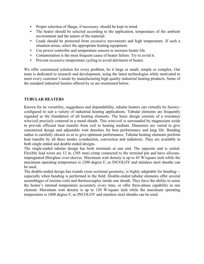
TUBULAR HEATERS
Known for its versatility, ruggedness and dependability, tubular heaters can virtually be factory-
configured to suit a variety of industrial heating applications. Tubular elements are frequently
regarded as the foundation of all heating elements. The basic design consists of a resistance
wire/coil precisely centered in a metal sheath. This wire/coil is surrounded by magnesium oxide
to provide efficient heat transfer from coil to heating medium. Diameters are varied to give
customized design and adjustable watt densities for best performance and long life. Bending
radius is carefully chosen so as to give optimum performance. Tubular heating elements perform
heat transfer by all three modes (conduction, convection and radiation). They are available in
both single ended and double ended designs.
The single-ended tubular design has both terminals at one end. The opposite end is sealed.
Flexible lead wires are 12 in. (305 mm) crimp connected to the terminal pin and have silicone-
impregnated fiberglass over-sleeves. Maximum watt density is up to 45 W/square inch while the
maximum operating temperature is 1200 degree F, so INCOLOY and stainless steel sheaths can
be used.
The double-ended design has rounds cross sectional geometry, is highly adaptable for bending—
especially when bending is performed in the field. Double-ended tubular elements offer several
assemblages of resistor coils and thermocouples inside one sheath. They have the ability to sense
the heater’s internal temperature accurately every time, or offer three-phase capability in one
element. Maximum watt density is up to 120 W/square inch while the maximum operating
temperature is 1800 degree F, so INCOLOY and stainless steel sheaths can be used.
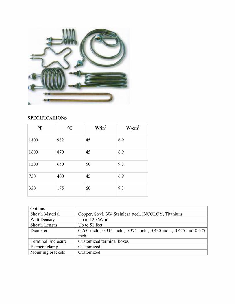
SPECIFICATIONS
°F °C W/in2 W/cm
2
1800 982 45 6.9
1600 870 45 6.9
1200 650 60 9.3
750 400 45 6.9
350 175 60 9.3
Options:
Sheath Material Copper, Steel, 304 Stainless steel, INCOLOY, Titanium
Watt Density Up to 120 W/in2
Sheath Length Up to 51 feet
Diameter 0.260 inch , 0.315 inch , 0.375 inch , 0.430 inch , 0.475 and 0.625
inch
Terminal Enclosure Customized terminal boxes
Element clamp Customized
Mounting brackets Customized
Electric tubular heaters fits almost every industrial heating applications ranging from immersion
to air heating that requires temperatures of 1382 degree F. They are made using high quality
alloys to minimize physical stress and offer high efficiency. Used to heat solids, liquids and
gases.
Material Application
Copper Water, Oil, Grease
Steel Alkaline cleaning solutions, Tars, Asphalt or air heating
Stainless Steel Corrosive liquids, food processing equipment, Radiant heating
Incoloy Cleaning and degreasing solutions, Corrosive liquids
Inconel Plating and pickling solutions, acid
Titanium Corrosive liquids
OPTIONS WITH TUBULAR HEATERS
Terminations
Double ended tubular is available with a variety of terminations while single ended tubular has
only flexible lead wires.
Bend Formations
Double-ended heating elements can be formed into spirals, compounds, multi-axis and multi-
planes etc. Custom bending is also available. However bending is not recommended with single
ended elements.
Mounting methods
Brackets, Mounting collars, Threaded Bulkheads are available.
Moisture Resistant Seals
It is important for the life and performance of the heater.
While selecting the ideal tubular elements for your application, please consider the following
factors:
• Heating element watt density
• Sheath material (corrosive or non corrosive)
• Temperature of the product
• Air velocity within the application
• Ambient temperature
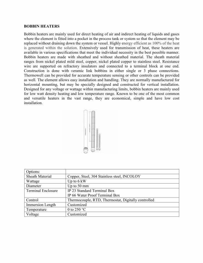
BOBBIN HEATERS
Bobbin heaters are mainly used for direct heating of air and indirect heating of liquids and gases
where the element is fitted into a pocket in the process tank or system so that the element may be
replaced without draining down the system or vessel. Highly energy efficient as 100% of the heat
is generated within the solution. Extensively used for transmission of heat, these heaters are
available in various specifications that meet the individual necessity in the best possible manner.
Bobbin heaters are made with sheathed and without sheathed material. The sheath material
ranges from nickel plated mild steel, copper, nickel plated copper to stainless steel. Resistance
wire are supported on refractory insulators and connected to a terminal block at one end.
Construction is done with Ceramic link bobbins in either single or 3 phase connections.
Thermowell can be provided for accurate temperature sensing or other controls can be provided
as well. The element allows easy installation and handling. They are normally manufactured for
horizontal mounting, but may be specially designed and constructed for vertical installation.
Designed for any voltage or wattage within manufacturing limits, bobbin heaters are mainly used
for low watt density heating and low temperature range. Known to be one of the most common
and versatile heaters in the vast range, they are economical, simple and have low cost
installation.
Options:
Sheath Material Copper, Steel, 304 Stainless steel, INCOLOY
Wattage Up to 6 kW
Diameter Up to 50 mm
Terminal Enclosure IP 23 Standard Terminal Box
IP 66 Water Proof Terminal Box
Control Thermocouple, RTD, Thermostat, Digitally controlled
Immersion Length Customized
Temperature 0 to 250 °C
Voltage Customized

Applications
• Heating liquids
• Heating wax, fats and bitumens
• Heating water and oil
Benefits
• High quality
• Long life span
• Good conductor
• Highly efficient
• Versatile and non polluting
• Highly suitable for low watt densities
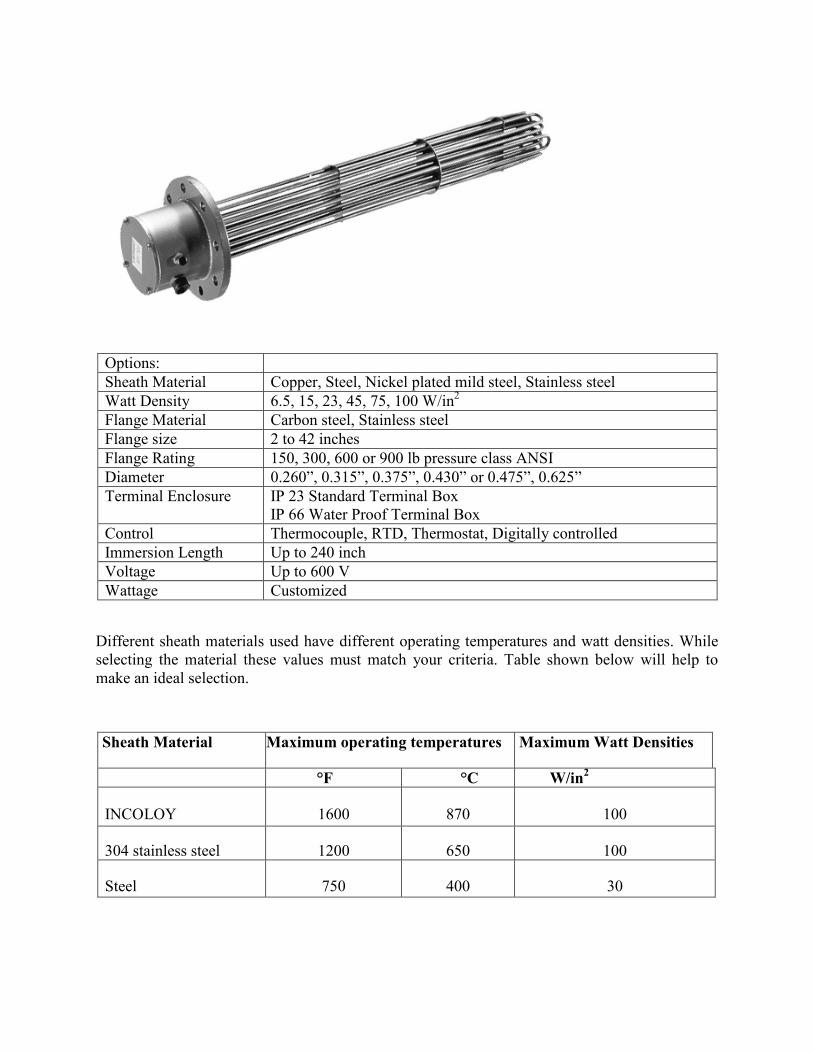
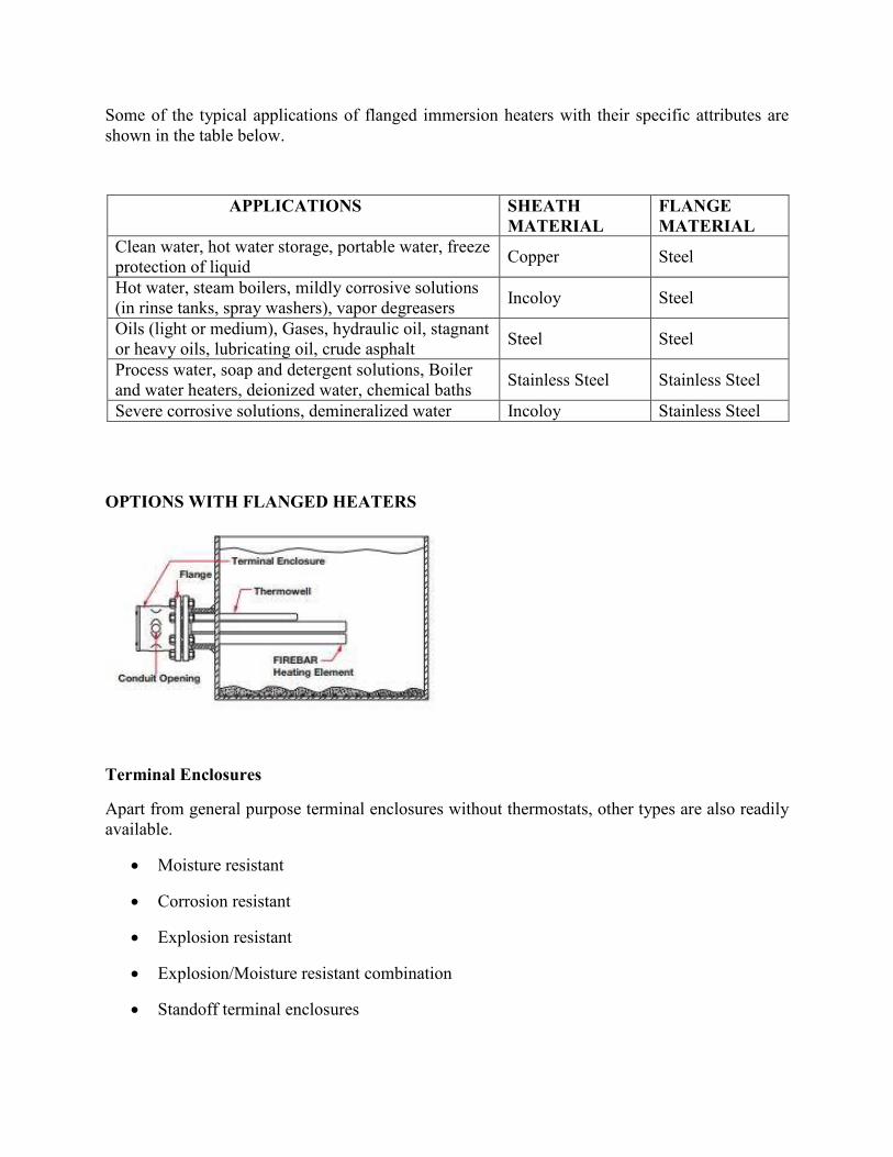
FLANGED IMMERSION HEATERS
Flanged industrial immersion heaters are amongst the most popular heaters owing to wide
customization, easier installation and operations in stringent environment. Made by brazing or
welding flange with several hairpin elements or bulge tubular elements, these are designed for
heating chemical, petroleum and water based applications specially heat transfer fluids, medium
and lightweight oils and water in tanks and pressure vessels. A thermocouple or RTD is often
used within the bundle of elements to maintain the desired target temperature. Extra wiring
boxes to make electrical connections are provided with it. Tubing known as a thermowell is used
to protect thermocouples and heating elements. Temperature readings are then transmitted to a
control unit that regulates power. Although, they occupy a small space, but have a large heating
element which is perfect for applications which require high wattage heating. This is one of the
most efficient forms of process heating with nearly 100 percent efficiency.
Different alloys and materials can be used to suit specific applications. For instance, steel flanges
are used for deionized water, lubricant oils, heavy and light oils, waxes as well as mildly
corrosive liquids and low flow gas and water tank heating. Stainless steel flanged heating
elements are used with mild and severe corrosive solutions and military applications. The sheath
materials used can be steel, stainless steel, copper as well as exotic alloys such as incoloy.
Options:
Sheath Material Copper, Steel, Nickel plated mild steel, Stainless steel
Watt Density 6.5, 15, 23, 45, 75, 100 W/in2
Flange Material Carbon steel, Stainless steel
Flange size 2 to 42 inches
Flange Rating 150, 300, 600 or 900 lb pressure class ANSI
Diameter 0.260”, 0.315”, 0.375”, 0.430” or 0.475”, 0.625”
Terminal Enclosure IP 23 Standard Terminal Box
IP 66 Water Proof Terminal Box
Control Thermocouple, RTD, Thermostat, Digitally controlled
Immersion Length Up to 240 inch
Voltage Up to 600 V
Wattage Customized
Different sheath materials used have different operating temperatures and watt densities. While
selecting the material these values must match your criteria. Table shown below will help to
make an ideal selection.
Sheath Material Maximum operating temperatures Maximum Watt Densities
°F °C W/in2
INCOLOY 1600 870 100
304 stainless steel 1200 650 100
Steel 750 400 30
Some of the typical applications of flanged immersion heaters with their specific attributes are
shown in the table below.
APPLICATIONS SHEATH
MATERIAL
FLANGE
MATERIAL
Clean water, hot water storage, portable water, freeze
protection of liquid Copper Steel
Hot water, steam boilers, mildly corrosive solutions
(in rinse tanks, spray washers), vapor degreasers Incoloy Steel
Oils (light or medium), Gases, hydraulic oil, stagnant
or heavy oils, lubricating oil, crude asphalt Steel Steel
Process water, soap and detergent solutions, Boiler
and water heaters, deionized water, chemical baths Stainless Steel Stainless Steel
Severe corrosive solutions, demineralized water Incoloy Stainless Steel
OPTIONS WITH FLANGED HEATERS
Terminal Enclosures
Apart from general purpose terminal enclosures without thermostats, other types are also readily
available.
• Moisture resistant
• Corrosion resistant
• Explosion resistant
• Explosion/Moisture resistant combination
• Standoff terminal enclosures
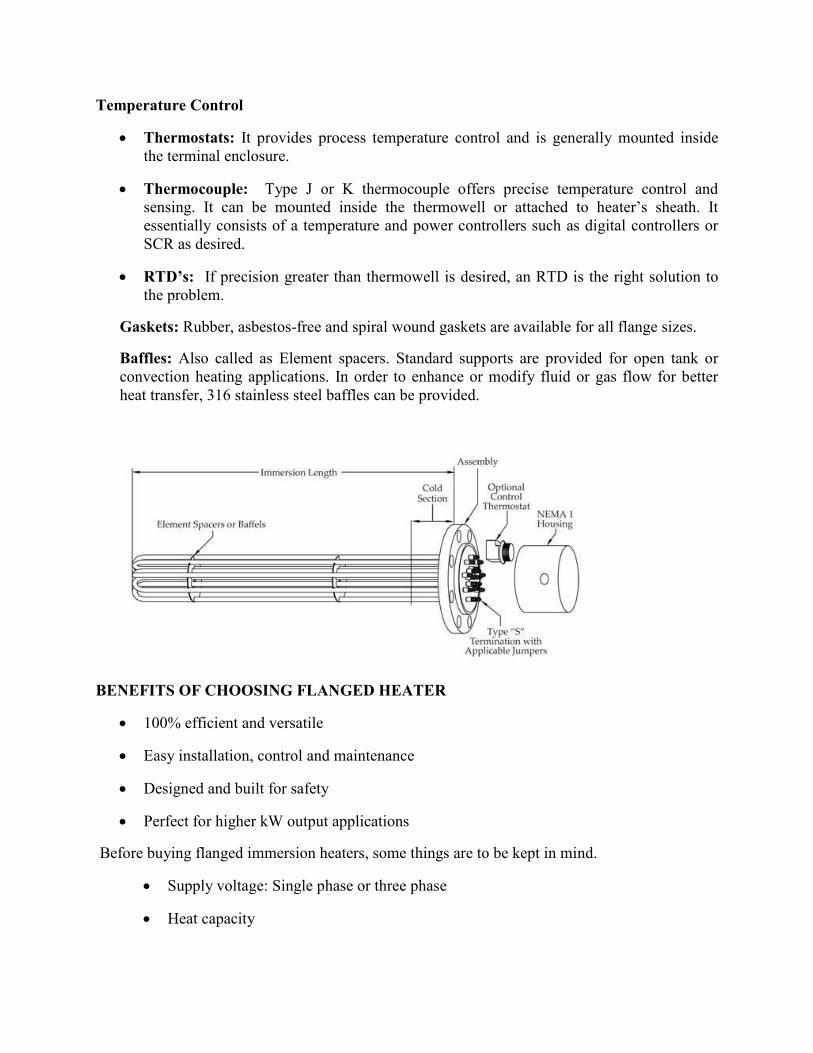
Temperature Control
• Thermostats: It provides process temperature control and is generally mounted inside
the terminal enclosure.
• Thermocouple: Type J or K thermocouple offers precise temperature control and
sensing. It can be mounted inside the thermowell or attached to heater’s sheath. It
essentially consists of a temperature and power controllers such as digital controllers or
SCR as desired.
• RTD’s: If precision greater than thermowell is desired, an RTD is the right solution to
the problem.
Gaskets: Rubber, asbestos-free and spiral wound gaskets are available for all flange sizes.
Baffles: Also called as Element spacers. Standard supports are provided for open tank or
convection heating applications. In order to enhance or modify fluid or gas flow for better
heat transfer, 316 stainless steel baffles can be provided.
BENEFITS OF CHOOSING FLANGED HEATER
• 100% efficient and versatile
• Easy installation, control and maintenance
• Designed and built for safety
• Perfect for higher kW output applications
Before buying flanged immersion heaters, some things are to be kept in mind.
• Supply voltage: Single phase or three phase
• Heat capacity
• Housing
• Sheath Materials
• Heating element materials
• Temperature controls
CIRCULATION HEATERS
Circulation heater (a.k.a inline heaters) is basically an immersion heater covered by an anti-
corrosion metallic vessel chamber. It is accompanied by National Pipe Thread (NPT) screw plug
or ANSI flange heater assemblies mated with a pressure vessel. The vessel is mainly used to
provide insulation to prevent heat loss in the circulation system. An inlet flange transports the
fluid into the circulation system, which is then circulated and heated until the desired
temperature is reached. The heating medium will then flow out of the output flange at a fixed
flow rate decided by the temperature control mechanism. Since it is a compact heating system,
the operation is fast and executed in a short time. The heat generated is evenly distributed and the
efficiency of the heater is high. Drain valves are also provided to remove leftover fluids or
residues. Temperature sensors can be used with any control to achieve the desired temperature
range. To manage the liquid flow rate of the heater, the wattage can be manipulated. When the
requirement is such that liquid is to be pumped around anyway, a circulation heater is a logical
choice.
Circulation heaters provide a ready-made means to install electric heating with a minimal
amount of time and labor. This is accomplished by combining heating elements, vessel,
insulation, terminal enclosure, mounting brackets and inlet and outlet connections into a
complete assembly. Such kinds of heaters are ideal for processing fluid, including hazardous
liquids that require intermediate heating while maintaining viscosity and flow rate, waste oil,
steam, gases, and liquids like DE-ionized water for use in semiconductor and electronics
industries. These heaters are specially used to heat up vegetable oils efficiently, so proper
viscosity is maintained during food manufacturing using indirect heating. For maintaining
correct viscosity, lower watt densities are recommended. Also no additional terminal box is
necessary for this application.
Options:
Sheath Material Copper, Steel, 316 Stainless steel, INCOLOY
Kilowatt Ratings 500 KW or lesser
Wearing Watt density 6.5 W/in2,15 W/in
2, 23 W/in
2, 45 W/in
2, 65W/in
2
Flange & Vessel Material Carbon steel, Stainless steel
Flange size Up to 42 inches
Flange Rating Up to 2500 lb pressure class ANSI
Terminal Enclosure IP 23 Standard Terminal Box
IP 66 Water Proof Terminal Box
Control Thermocouple, RTD, Thermostat, Digitally controlled
Terminal Enclosure Standoff 4 or 6 inches
Terminal Seals silicon resin, silcone fluid, RTV, epoxy or hermetic
Standard Size 1.25” NPT Screw Plug size to 14” diameter
Flange Gasket Standard, Spiral wound or any other
Thermal Insulation Standard, High temperature or weather proof jacket
Mounting position Horizontal or Vertical
Different alloys and materials can be used to suit specific applications. The table below shows
working temperatures and watt densities of variety of materials
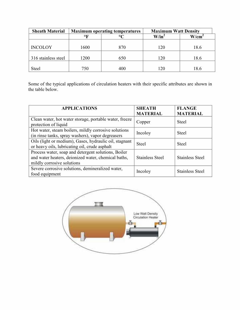
Sheath Material Maximum operating temperatures Maximum Watt Density
°F °C W/in2 W/cm
2
INCOLOY 1600 870 120 18.6
316 stainless steel 1200 650 120 18.6
Steel 750 400 120 18.6
Some of the typical applications of circulation heaters with their specific attributes are shown in
the table below.
APPLICATIONS SHEATH
MATERIAL
FLANGE
MATERIAL
Clean water, hot water storage, portable water, freeze
protection of liquid Copper Steel
Hot water, steam boilers, mildly corrosive solutions
(in rinse tanks, spray washers), vapor degreasers Incoloy Steel
Oils (light or medium), Gases, hydraulic oil, stagnant
or heavy oils, lubricating oil, crude asphalt Steel Steel
Process water, soap and detergent solutions, Boiler
and water heaters, deionized water, chemical baths,
mildly corrosive solutions
Stainless Steel Stainless Steel
Severe corrosive solutions, demineralized water,
food equipment Incoloy Stainless Steel
FEATURES & BENEFITS
• Thermal insulation provided to prevent heat loss
• Mounting lugs provided for support
• Different terminal enclosures available for easy wiring
• Digitally controlled for precision
• Baffles and flange mounting holes provided.
• Easy to install, compact, clean and durable
• Works in conjunction with control panels
• Custom designed to meet specifications.
• Highly energy efficient and provide maximum dielectric strength.
• Compatible with standard industry piping and safety standards.
• Gaskets and mounting lugs provided as per specifications.
PIPE HEATERS
As the name suggests, Pipe Heaters are specifically manufactured to fit inside 2 or 3” pipes,
which can then be utilized in tanks for heating. Pipe heaters do not actually touch the liquid
being heated. Indirect heating from heating element to pipe is used to heat the liquid. The heating
process can be compared to that of an oven in which the actual end of the device that radiates
heat is installed inside of the tank whereas controller box is kept outside. An integrated digital
controller can be used that acts as a closed loop system and regulates the heat intensity. Steel
pipes can be used for good heat transfer properties and corrosion resistant to petrochemical
solutions. Pipe heaters do not require much maintenance, as the tank does not need to be emptied
out if the industrial heater needs to be replaced. Also, since the heater is not entirely exposed to
the tank, there is no fear for sludge or carbon contamination to develop. They can use any
configuration such as flange, screw plug or resistance coil.
These heaters are useful in tanks that require extremely low watt densities such as waxes, thick
liquids such as tar, molasses and corrosive mediums. Designed to withstand high heat
environments, pipe heaters are commendable to be used with heavy bunker fuel oils, corrosive
liquids and liquids with high viscosity.
Installation: For this type of heaters, there are two methods to install. The nozzle can be
attached directly to the tank or it can be welded. Welding is more preferred as it is easy to make
modifications this way simply by cutting a hole in the tank to carry the process.
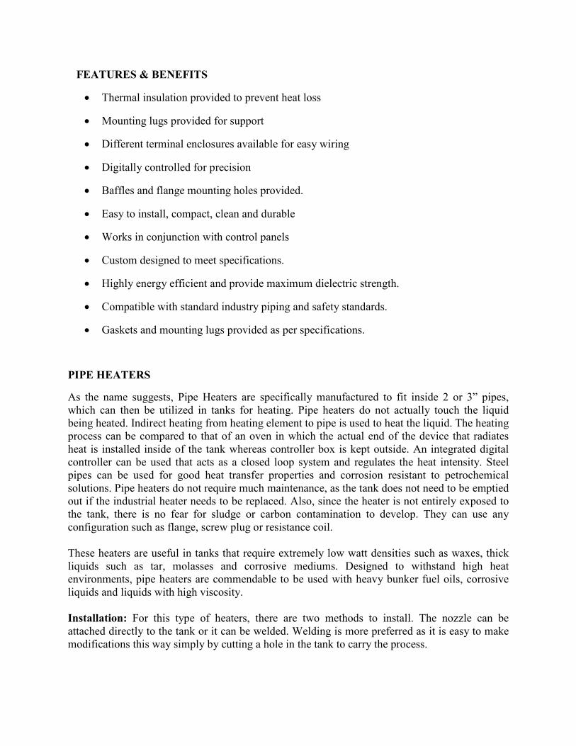
System Type Application Operating Temperature KW Construction
Open coil elements Pipe Insert 0-750F 4-20 N/A
Large flexible tank Below ground storage
tank
50-225 6-80 NPT and
welded
Large single immersion
tank
Viscous fluid 50-400 15-72 Welded
Options:
Pipe Size 2 or 3 inches, 40 NPS
Wattage 4-20 kW
Watt Density 3 to 12 W/square inch
Voltage 240, 480 or 600 V, 3 phase
Flange size 4 to 14 inches
Flange Rating 150 lb pressure class ANSI
Length 60 to 320 inch (5-26 ft.)
Outside Diameters 1 7/8 or 2 ¾ inch
Features and Benefits
• Equipped with high density electrical ceramic insulating supports
• Can be bent in a vertical plane on at least 12’’ radius
• Heavy gauge bus bars and resistance wires
• Easy installation and very flexible
• Long service life and uniform heat distribution
• Equipped with a continuous support bar that ensures proper rigidity
When opting for a pipe heater, consider these things
• Tank size and liquid amount that is to be drained.
• Size, installation and maintenance cost, lifetime of the heater itself.
• Storing of liquid or any content that is to be heated when repairs are to be made.
• If the content is hazardous like chemicals, toxicants or other corrosive elements,must be
isolated far from physical contact as well as kept away from other devices and
machinery.
• Heating time, handling and servicing personnel availability and all matters must be
accounted for.
CONFIGURATIONS WITH PIPE HEATERS
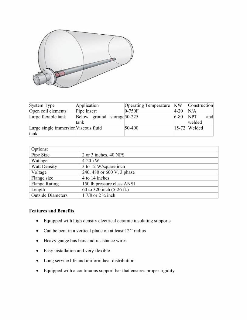
Pipe heater with coil Element
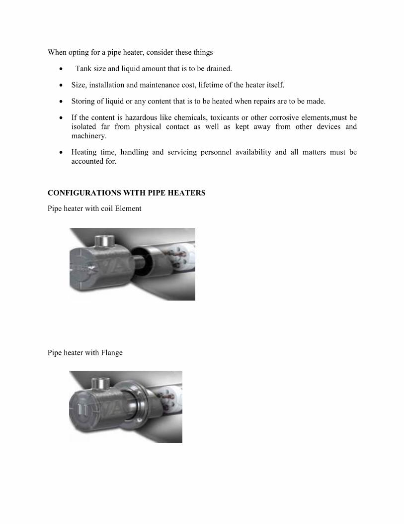
Pipe heater with Flange
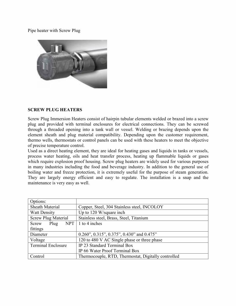
Pipe heater with Screw Plug
SCREW PLUG HEATERS
Screw Plug Immersion Heaters consist of hairpin tubular elements welded or brazed into a screw
plug and provided with terminal enclosures for electrical connections. They can be screwed
through a threaded opening into a tank wall or vessel. Welding or brazing depends upon the
element sheath and plug material compatibility. Depending upon the customer requirement,
thermo wells, thermostats or control panels can be used with these heaters to meet the objective
of precise temperature control.
Used as a direct heating element, they are ideal for heating gases and liquids in tanks or vessels,
process water heating, oils and heat transfer process, heating up flammable liquids or gases
which require explosion proof housing. Screw plug heaters are widely used for various purposes
in many industries including the food and beverage industry. In addition to the general use of
boiling water and freeze protection, it is extremely useful for the purpose of steam generation.
They are largely energy efficient and easy to regulate. The installation is a snap and the
maintenance is very easy as well.
Options:
Sheath Material Copper, Steel, 304 Stainless steel, INCOLOY
Watt Density Up to 120 W/square inch
Screw Plug Material Stainless steel, Brass, Steel, Titanium
Screw Plug NPT
fittings
1 to 4 inches
Diameter 0.260”, 0.315”, 0.375”, 0.430” and 0.475”
Voltage 120 to 480 V AC Single phase or three phase
Terminal Enclosure IP 23 Standard Terminal Box
IP 66 Water Proof Terminal Box
Control Thermocouple, RTD, Thermostat, Digitally controlled
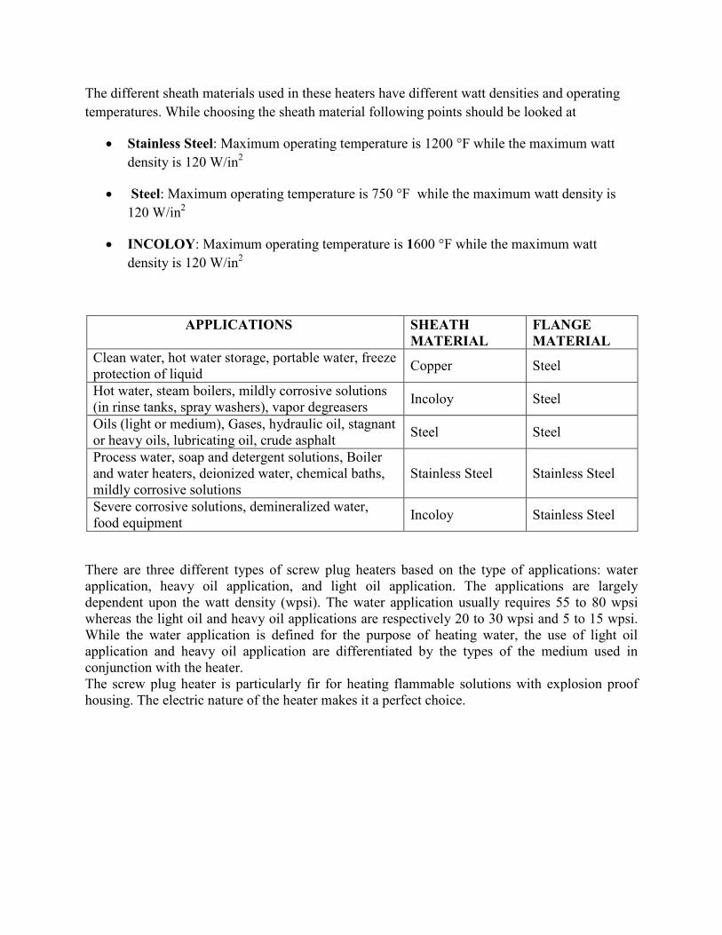
The different sheath materials used in these heaters have different watt densities and operating
temperatures. While choosing the sheath material following points should be looked at
• Stainless Steel: Maximum operating temperature is 1200 °F while the maximum watt
density is 120 W/in2
• Steel: Maximum operating temperature is 750 °F while the maximum watt density is
120 W/in2
• INCOLOY: Maximum operating temperature is 1600 °F while the maximum watt
density is 120 W/in2
APPLICATIONS SHEATH
MATERIAL
FLANGE
MATERIAL
Clean water, hot water storage, portable water, freeze
protection of liquid Copper Steel
Hot water, steam boilers, mildly corrosive solutions
(in rinse tanks, spray washers), vapor degreasers Incoloy Steel
Oils (light or medium), Gases, hydraulic oil, stagnant
or heavy oils, lubricating oil, crude asphalt Steel Steel
Process water, soap and detergent solutions, Boiler
and water heaters, deionized water, chemical baths,
mildly corrosive solutions
Stainless Steel Stainless Steel
Severe corrosive solutions, demineralized water,
food equipment Incoloy Stainless Steel
There are three different types of screw plug heaters based on the type of applications: water
application, heavy oil application, and light oil application. The applications are largely
dependent upon the watt density (wpsi). The water application usually requires 55 to 80 wpsi
whereas the light oil and heavy oil applications are respectively 20 to 30 wpsi and 5 to 15 wpsi.
While the water application is defined for the purpose of heating water, the use of light oil
application and heavy oil application are differentiated by the types of the medium used in
conjunction with the heater.
The screw plug heater is particularly fir for heating flammable solutions with explosion proof
housing. The electric nature of the heater makes it a perfect choice.
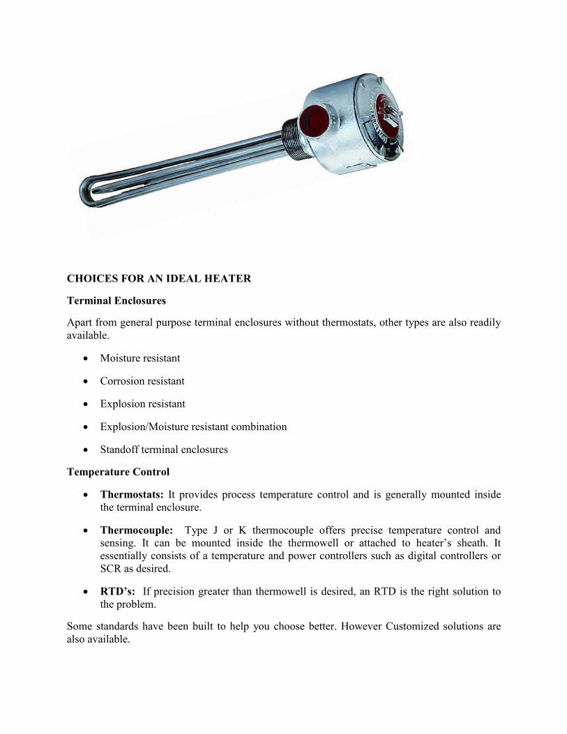
CHOICES FOR AN IDEAL HEATER
Terminal Enclosures
Apart from general purpose terminal enclosures without thermostats, other types are also readily
available.
• Moisture resistant
• Corrosion resistant
• Explosion resistant
• Explosion/Moisture resistant combination
• Standoff terminal enclosures
Temperature Control
• Thermostats: It provides process temperature control and is generally mounted inside
the terminal enclosure.
• Thermocouple: Type J or K thermocouple offers precise temperature control and
sensing. It can be mounted inside the thermowell or attached to heater’s sheath. It
essentially consists of a temperature and power controllers such as digital controllers or
SCR as desired.
• RTD’s: If precision greater than thermowell is desired, an RTD is the right solution to
the problem.
Some standards have been built to help you choose better. However Customized solutions are
also available.
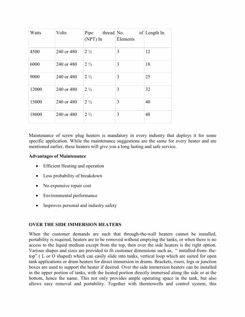
Watts Volts Pipe thread
(NPT) In
No. of
Elements
Length In.
4500 240 or 480 2 ½ 3 12
6000 240 or 480 2 ½ 3 18
9000 240 or 480 2 ½ 3 25
12000 240 or 480 2 ½ 3 32
15000 240 or 480 2 ½ 3 40
18000 240 or 480 2 ½ 3 48
Maintenance of screw plug heaters is mandatory in every industry that deploys it for some
specific application. While the maintenance suggestions are the same for every heater and are
mentioned earlier, these heaters will give you a long lasting and safe service.
Advantages of Maintenance
• Efficient Heating and operation
• Less probability of breakdown
• No expensive repair cost
• Environmental performance
• Improves personal and industry safety
OVER THE SIDE IMMERSION HEATERS
When the customer demands are such that through-the-wall heaters cannot be installed,
portability is required, heaters are to be removed without emptying the tanks, or when there is no
access to the liquid medium except from the top, then over the side heaters is the right option.
Various shapes and sizes are provided to fit customer dimensions such as, “ installed-from- the-
top” ( L or O shaped) which can easily slide into tanks, vertical loop which are suited for open
tank applications or drum heaters for direct immersion in drums. Brackets, risers, legs or junction
boxes are used to support the heater if desired. Over the side immersion heaters can be installed
in the upper portion of tanks, with the heated portion directly immersed along the side or at the
bottom, hence the name. This not only provides ample operating space in the tank, but also
allows easy removal and portability. Together with thermowells and control system, this
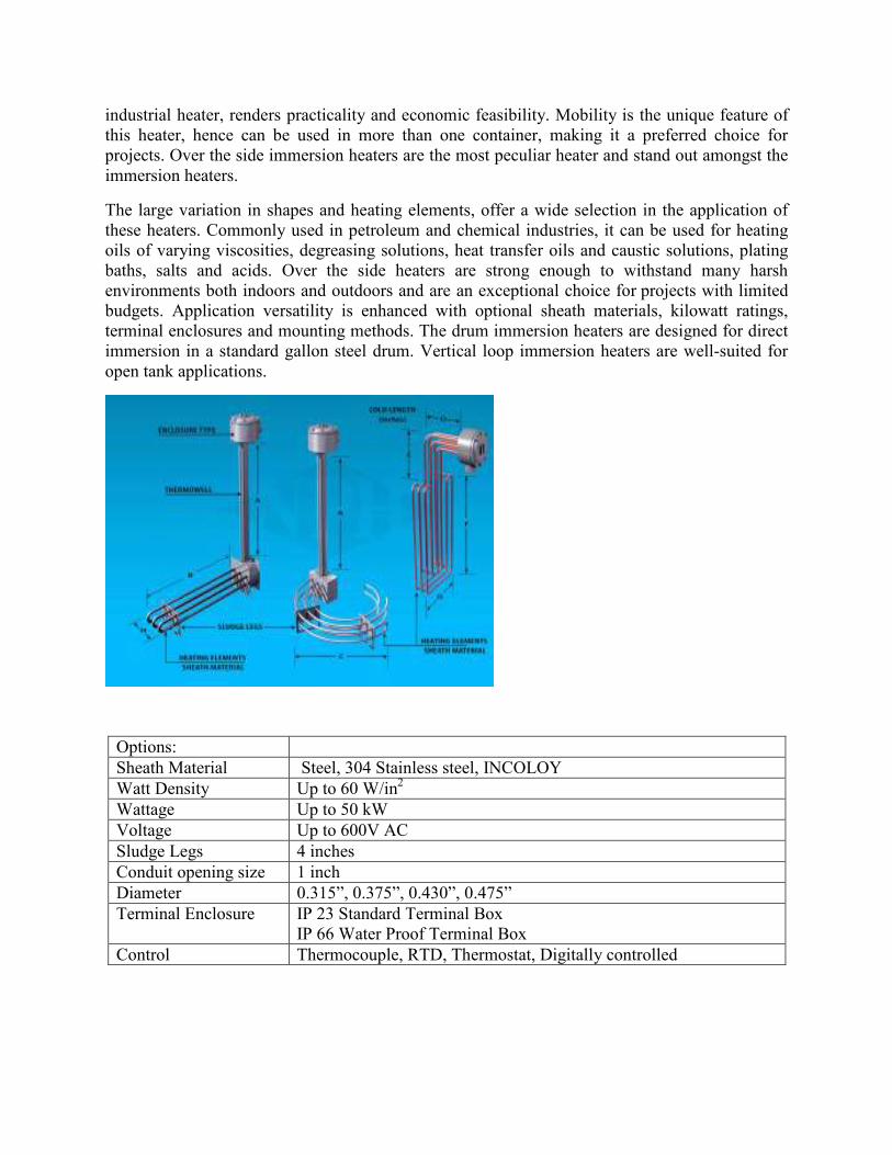
industrial heater, renders practicality and economic feasibility. Mobility is the unique feature of
this heater, hence can be used in more than one container, making it a preferred choice for
projects. Over the side immersion heaters are the most peculiar heater and stand out amongst the
immersion heaters.
The large variation in shapes and heating elements, offer a wide selection in the application of
these heaters. Commonly used in petroleum and chemical industries, it can be used for heating
oils of varying viscosities, degreasing solutions, heat transfer oils and caustic solutions, plating
baths, salts and acids. Over the side heaters are strong enough to withstand many harsh
environments both indoors and outdoors and are an exceptional choice for projects with limited
budgets. Application versatility is enhanced with optional sheath materials, kilowatt ratings,
terminal enclosures and mounting methods. The drum immersion heaters are designed for direct
immersion in a standard gallon steel drum. Vertical loop immersion heaters are well-suited for
open tank applications.
Options:
Sheath Material Steel, 304 Stainless steel, INCOLOY
Watt Density Up to 60 W/in2
Wattage Up to 50 kW
Voltage Up to 600V AC
Sludge Legs 4 inches
Conduit opening size 1 inch
Diameter 0.315”, 0.375”, 0.430”, 0.475”
Terminal Enclosure IP 23 Standard Terminal Box
IP 66 Water Proof Terminal Box
Control Thermocouple, RTD, Thermostat, Digitally controlled
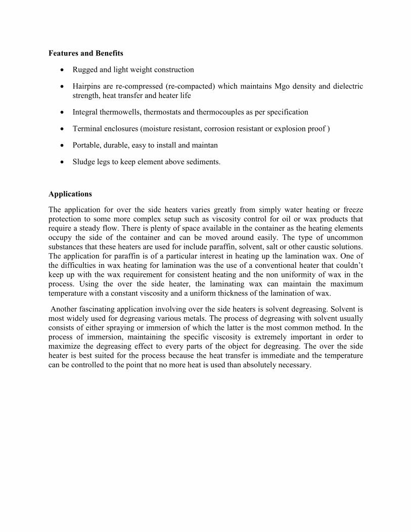
Features and Benefits
• Rugged and light weight construction
• Hairpins are re-compressed (re-compacted) which maintains Mgo density and dielectric
strength, heat transfer and heater life
• Integral thermowells, thermostats and thermocouples as per specification
• Terminal enclosures (moisture resistant, corrosion resistant or explosion proof )
• Portable, durable, easy to install and maintan
• Sludge legs to keep element above sediments.
Applications
The application for over the side heaters varies greatly from simply water heating or freeze
protection to some more complex setup such as viscosity control for oil or wax products that
require a steady flow. There is plenty of space available in the container as the heating elements
occupy the side of the container and can be moved around easily. The type of uncommon
substances that these heaters are used for include paraffin, solvent, salt or other caustic solutions.
The application for paraffin is of a particular interest in heating up the lamination wax. One of
the difficulties in wax heating for lamination was the use of a conventional heater that couldn’t
keep up with the wax requirement for consistent heating and the non uniformity of wax in the
process. Using the over the side heater, the laminating wax can maintain the maximum
temperature with a constant viscosity and a uniform thickness of the lamination of wax.
Another fascinating application involving over the side heaters is solvent degreasing. Solvent is
most widely used for degreasing various metals. The process of degreasing with solvent usually
consists of either spraying or immersion of which the latter is the most common method. In the
process of immersion, maintaining the specific viscosity is extremely important in order to
maximize the degreasing effect to every parts of the object for degreasing. The over the side
heater is best suited for the process because the heat transfer is immediate and the temperature
can be controlled to the point that no more heat is used than absolutely necessary.
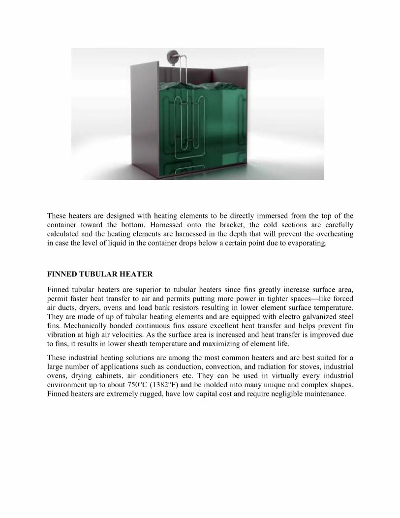
These heaters are designed with heating elements to be directly immersed from the top of the
container toward the bottom. Harnessed onto the bracket, the cold sections are carefully
calculated and the heating elements are harnessed in the depth that will prevent the overheating
in case the level of liquid in the container drops below a certain point due to evaporating.
FINNED TUBULAR HEATER
Finned tubular heaters are superior to tubular heaters since fins greatly increase surface area,
permit faster heat transfer to air and permits putting more power in tighter spaces—like forced
air ducts, dryers, ovens and load bank resistors resulting in lower element surface temperature.
They are made of up of tubular heating elements and are equipped with electro galvanized steel
fins. Mechanically bonded continuous fins assure excellent heat transfer and helps prevent fin
vibration at high air velocities. As the surface area is increased and heat transfer is improved due
to fins, it results in lower sheath temperature and maximizing of element life.
These industrial heating solutions are among the most common heaters and are best suited for a
large number of applications such as conduction, convection, and radiation for stoves, industrial
ovens, drying cabinets, air conditioners etc. They can be used in virtually every industrial
environment up to about 750°C (1382°F) and be molded into many unique and complex shapes.
Finned heaters are extremely rugged, have low capital cost and require negligible maintenance.
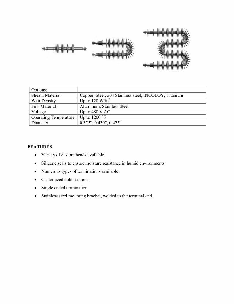
Options:
Sheath Material Copper, Steel, 304 Stainless steel, INCOLOY, Titanium
Watt Density Up to 120 W/in2
Fins Material Aluminum, Stainless Steel
Voltage Up to 480 V AC
Operating Temperature Up to 1200 °F
Diameter 0.375”, 0.430”, 0.475”
FEATURES
• Variety of custom bends available
• Silicone seals to ensure moisture resistance in humid environments.
• Numerous types of terminations available
• Customized cold sections
• Single ended termination
• Stainless steel mounting bracket, welded to the terminal end.
Material Applications
Copper Water
Oil
Grease
Solutions non-corrosive to copper
Steel Alkaline cleaning solutions
Tars
Asphalt
Air heating
Stainless steel Corrosive liquids
Food processing equipment
Radiant heating
Incoloy® Cleaning and degreasing solutions
Corrosive liquids
Inconel® Plating and pickling solutions
Acid
Titanium Corrosive liquids
BENEFITS
• Increase in surface area to approximately 16 square inches for every linear inch of
element length.
• Precise and easy control of heat output
• Easy to install and replace
• Provides protection against humid storage conditions
• Configurable to virtually any shape
• Compact size and durable
STRIP HEATERS
Strip heaters, commonly called component or clamp heaters, based on the principle of
convection air heating, use surface area to transfer heat effectively. Using most advanced heat
technologies, strip heaters are an outstanding industrial heating product. It comprises of a heating
element, a protective sleeve or sheath, and mounting hardware and can be clamped or bolted
onto objects or solid surfaces. A coiled nickel chromium element wire is placed in the center of
the heater. The element wire is then embedded in magnesium oxide (MgO)-based insulation and
compacted into a solid mass creating excellent heat conductivity and high dielectric strength. The
heater is then enclosed in desired sheathing. Suitable to work in 500 degree F temperatures,
magnesium oxide is used for increasing efficiency. Temperatures can be controlled by using a
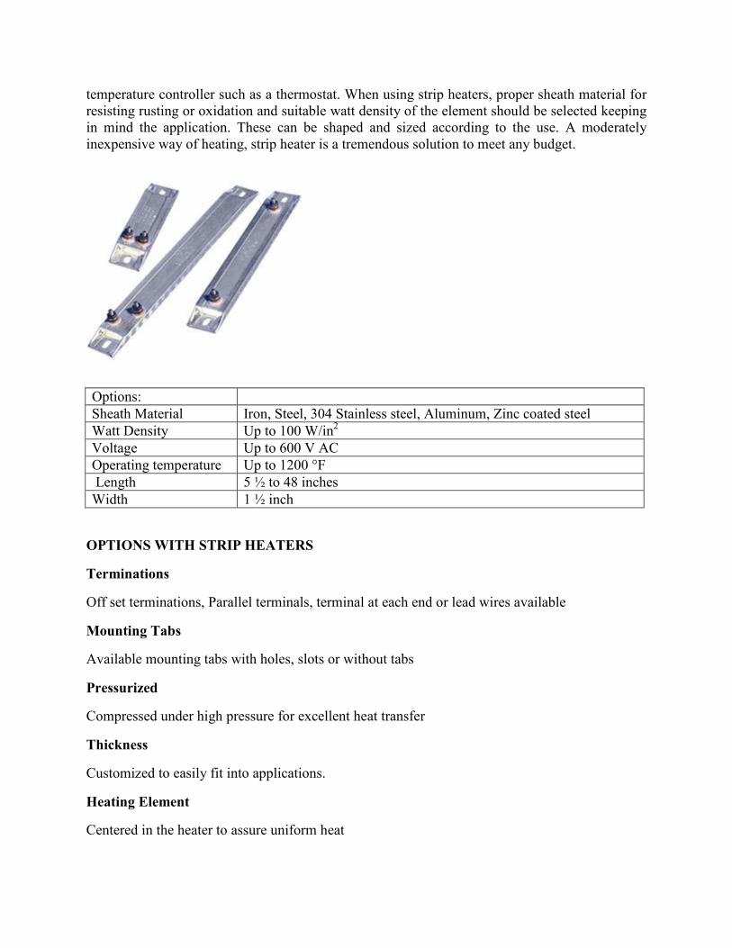
temperature controller such as a thermostat. When using strip heaters, proper sheath material for
resisting rusting or oxidation and suitable watt density of the element should be selected keeping
in mind the application. These can be shaped and sized according to the use. A moderately
inexpensive way of heating, strip heater is a tremendous solution to meet any budget.
Options:
Sheath Material Iron, Steel, 304 Stainless steel, Aluminum, Zinc coated steel
Watt Density Up to 100 W/in2
Voltage Up to 600 V AC
Operating temperature Up to 1200 °F
Length 5 ½ to 48 inches
Width 1 ½ inch
OPTIONS WITH STRIP HEATERS
Terminations
Off set terminations, Parallel terminals, terminal at each end or lead wires available
Mounting Tabs
Available mounting tabs with holes, slots or without tabs
Pressurized
Compressed under high pressure for excellent heat transfer
Thickness
Customized to easily fit into applications.
Heating Element
Centered in the heater to assure uniform heat
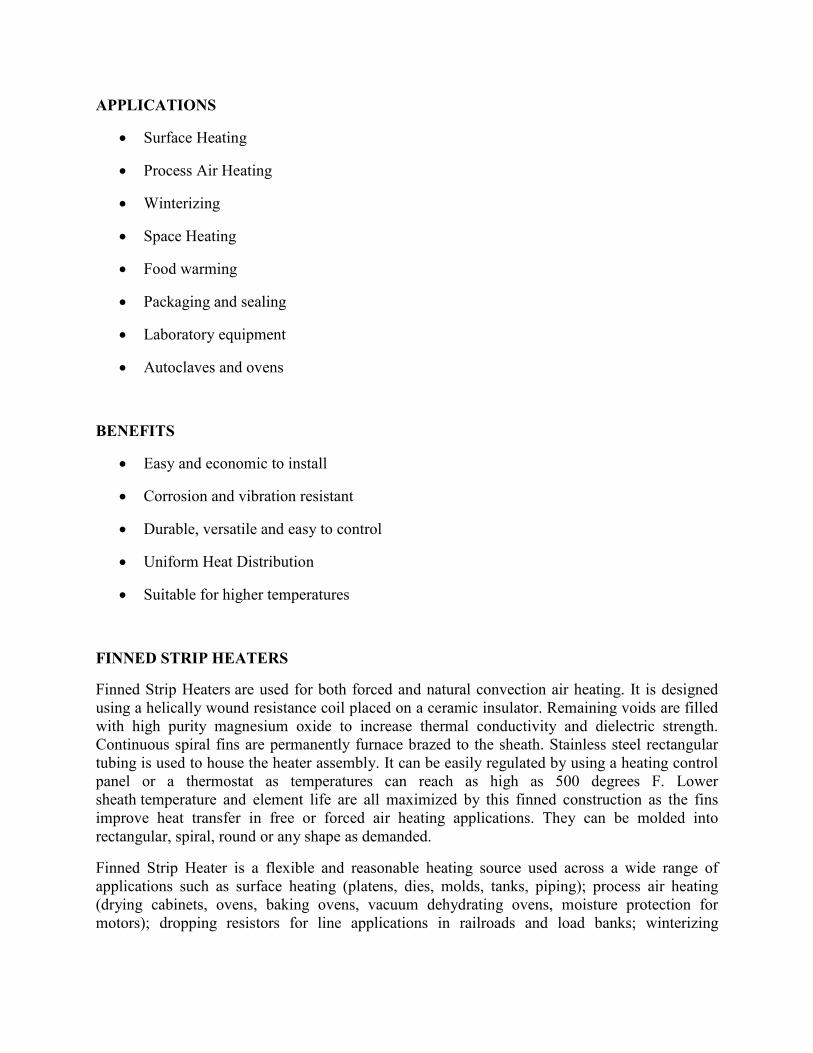
APPLICATIONS
• Surface Heating
• Process Air Heating
• Winterizing
• Space Heating
• Food warming
• Packaging and sealing
• Laboratory equipment
• Autoclaves and ovens
BENEFITS
• Easy and economic to install
• Corrosion and vibration resistant
• Durable, versatile and easy to control
• Uniform Heat Distribution
• Suitable for higher temperatures
FINNED STRIP HEATERS
Finned Strip Heaters are used for both forced and natural convection air heating. It is designed
using a helically wound resistance coil placed on a ceramic insulator. Remaining voids are filled
with high purity magnesium oxide to increase thermal conductivity and dielectric strength.
Continuous spiral fins are permanently furnace brazed to the sheath. Stainless steel rectangular
tubing is used to house the heater assembly. It can be easily regulated by using a heating control
panel or a thermostat as temperatures can reach as high as 500 degrees F. Lower
sheath temperature and element life are all maximized by this finned construction as the fins
improve heat transfer in free or forced air heating applications. They can be molded into
rectangular, spiral, round or any shape as demanded.
Finned Strip Heater is a flexible and reasonable heating source used across a wide range of
applications such as surface heating (platens, dies, molds, tanks, piping); process air heating
(drying cabinets, ovens, baking ovens, vacuum dehydrating ovens, moisture protection for
motors); dropping resistors for line applications in railroads and load banks; winterizing
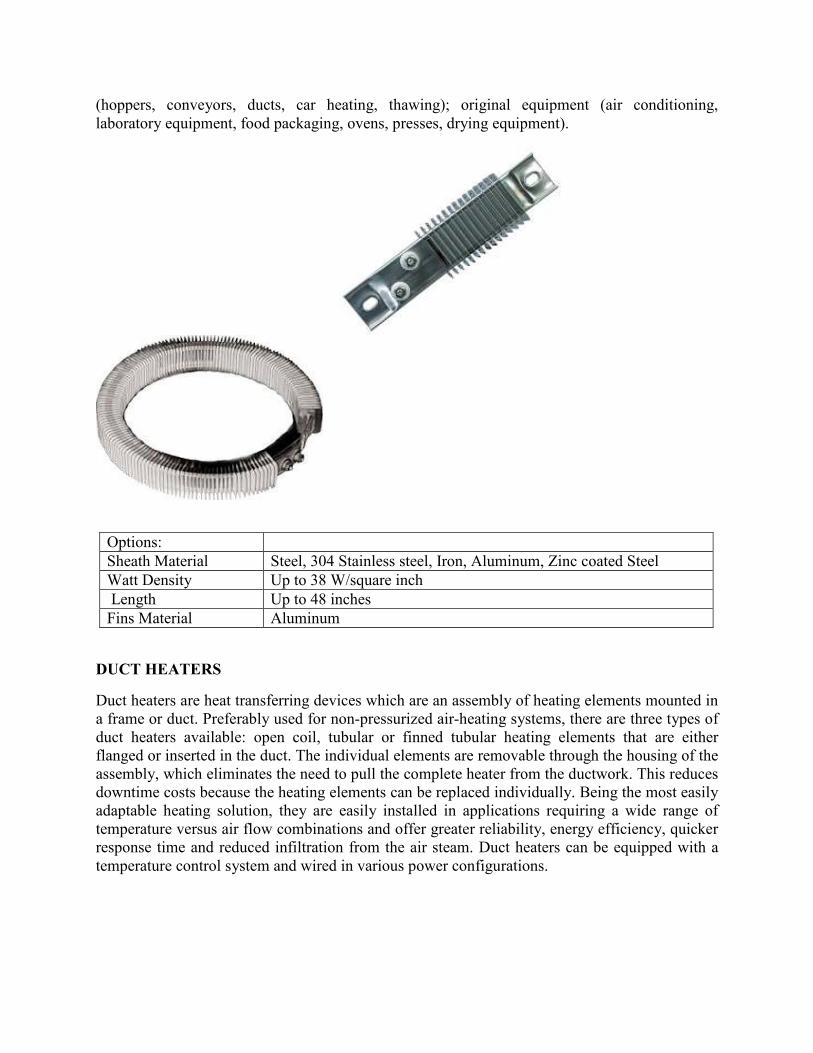
(hoppers, conveyors, ducts, car heating, thawing); original equipment (air conditioning,
laboratory equipment, food packaging, ovens, presses, drying equipment).
Options:
Sheath Material Steel, 304 Stainless steel, Iron, Aluminum, Zinc coated Steel
Watt Density Up to 38 W/square inch
Length Up to 48 inches
Fins Material Aluminum
DUCT HEATERS
Duct heaters are heat transferring devices which are an assembly of heating elements mounted in
a frame or duct. Preferably used for non-pressurized air-heating systems, there are three types of
duct heaters available: open coil, tubular or finned tubular heating elements that are either
flanged or inserted in the duct. The individual elements are removable through the housing of the
assembly, which eliminates the need to pull the complete heater from the ductwork. This reduces
downtime costs because the heating elements can be replaced individually. Being the most easily
adaptable heating solution, they are easily installed in applications requiring a wide range of
temperature versus air flow combinations and offer greater reliability, energy efficiency, quicker
response time and reduced infiltration from the air steam. Duct heaters can be equipped with a
temperature control system and wired in various power configurations.
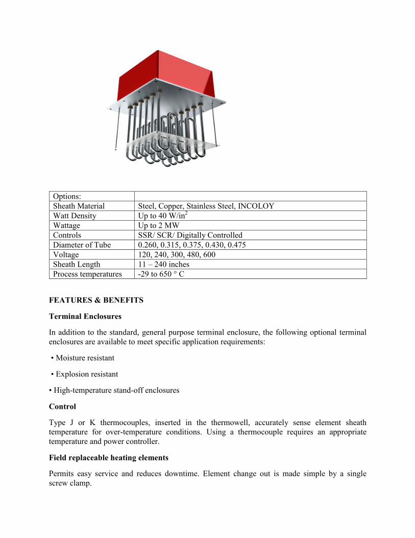
Options:
Sheath Material Steel, Copper, Stainless Steel, INCOLOY
Watt Density Up to 40 W/in2
Wattage Up to 2 MW
Controls SSR/ SCR/ Digitally Controlled
Diameter of Tube 0.260, 0.315, 0.375, 0.430, 0.475
Voltage 120, 240, 300, 480, 600
Sheath Length 11 – 240 inches
Process temperatures -29 to 650 ° C
FEATURES & BENEFITS
Terminal Enclosures
In addition to the standard, general purpose terminal enclosure, the following optional terminal
enclosures are available to meet specific application requirements:
• Moisture resistant
• Explosion resistant
• High-temperature stand-off enclosures
Control
Type J or K thermocouples, inserted in the thermowell, accurately sense element sheath
temperature for over-temperature conditions. Using a thermocouple requires an appropriate
temperature and power controller.
Field replaceable heating elements
Permits easy service and reduces downtime. Element change out is made simple by a single
screw clamp.
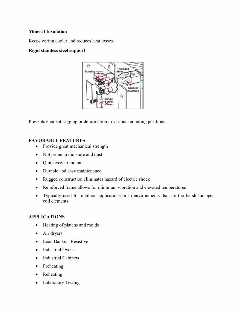
Mineral Insulation
Keeps wiring cooler and reduces heat losses.
Rigid stainless steel support
Prevents element sagging or deformation in various mounting positions
FAVORABLE FEATURES
• Provide great mechanical strength
• Not prone to moisture and dust
• Quite easy to mount
• Durable and easy maintenance
• Rugged construction eliminates hazard of electric shock
• Reinforced frame allows for minimum vibration and elevated temperatures
• Typically used for outdoor applications or in environments that are too harsh for open
coil elements
APPLICATIONS
• Heating of platens and molds
• Air dryers
• Load Banks – Resistive
• Industrial Ovens
• Industrial Cabinets
• Preheating
• Reheating
• Laboratory Testing
OPTIONS
Tubular duct heaters offer a number of options
• Digital controls, Contactors, Relays, SCRs available for the most accurate temperature
readings
• Disconnecting switches, airflow switches to help control unexpected pressure drops
• Fuse blocks and optional fuses available for low resistance and cool operations.
• Manual reset limit thermal cutout is used to prevent excessive temperatures with this the
terminal housing
BUNDLE ROD HEATERS
As the name suggests, bundle rod heater consists of circular ceramic beads that hold the heating
elements. They are designed for long life and maintenance free operation. The elements can be
provided in almost any length but the standard dimensions available are 68 to 170 mm (2.6 to 6.6
inch). These heaters can be used as standalone elements or inside radiant tubes. Because of the
ingenious design, Bundle rod heating elements deliver a much higher power (up to 100kW) than
conventional cartridge heaters. In combination with the radiant tubes, a system is created which
delivers high power, is rugged, versatile and needs low maintenance. Designed & manufactured
in low voltages for faster heating in order to achieve temperatures quickly, these heaters can be
mounted horizontally or vertically. Either NiCr alloy or FeCrAl alloy can be used as heating
element. For temperatures up to 2100°F (1150°C), Austenitic (NiCr) alloy (80/20 or 70/30) and
for temperatures up to 2597°F (1425°C), Ferritic (FeCrAl) alloy can be used. A comparison
between bundle rod and cartridge heaters shows their effectiveness:
Superior Power Output
Bundle rod elements, with a higher power output, leads to major saving in cost and maintenance.
Also when combined with Kanthal radiant tubes, they give highest power rating (up to 100 kW)
as compared to any other heater.
Easy installation
Due to its ruggedness and versatility, bundle rod elements are easy to install and replace.
Compatibility with radiant tubes allows installation to be either horizontal or vertical depending
on the application. Easy repair and high temperature performance gives it an edge over others.
Custom designed for the voltage and wattage required, bundle rod heaters are used in heat treat
furnaces and die casting machines to molten salt baths and incinerators. With radiant tubes they
can be used in high velocity convection furnaces and sealed quenched furnaces. They are also
useful in converting gas-fired furnaces to electric heating.
COMPONENTS OF BUNDLE ROD HEATERS
• Terminal Rod: Carries the power supply wiring. Usually made of SS 310 or INCOLOY.
Number of rods depends upon the supply connection.
• Center Rod: Used to provide central support to the heater. Usually made of SS 310 or
INCOLOY. Is longer than the terminal rods.
• Ceramic Disc: Used to encompass all the heating elements to form a bundle. Made of
Alumina. Usually flower shape.
• Fiber Disc: Used to hold the terminal rods and central rod together. Inserted in the cold
zone of the heater. Made of ceramic fiber.
Options:
Heating Element Material NiCr / FeCrAl alloy
Wattage 45 kW / 100 kW
Max. Temperature 1200 ° C / 1425 ° C
Diameter 68 to 170 mm
Length Customized
Voltage 240 or 480 V AC, Single phase or three phase
The surface load has some limitations depending upon the temperature. A table shown below
gives a brief idea:
Temperature Max. Surface Load (W/cm²)
800 °C 3.0
1000 °C 2.0
1400 °C < 1.0
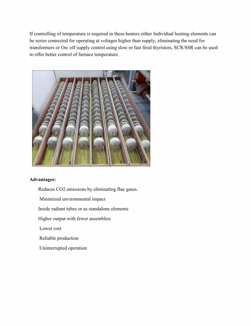
If controlling of temperature is required in these heaters either Individual heating elements can
be series connected for operating at voltages higher than supply, eliminating the need for
transformers or On/ off supply control using slow or fast fired thyristors, SCR/SSR can be used
to offer better control of furnace temperature.
Advantages:
Reduces CO2 emissions by eliminating flue gases.
Minimized environmental impact
Inside radiant tubes or as standalone elements
Higher output with fewer assemblies
Lower cost
Reliable production
Uninterrupted operation
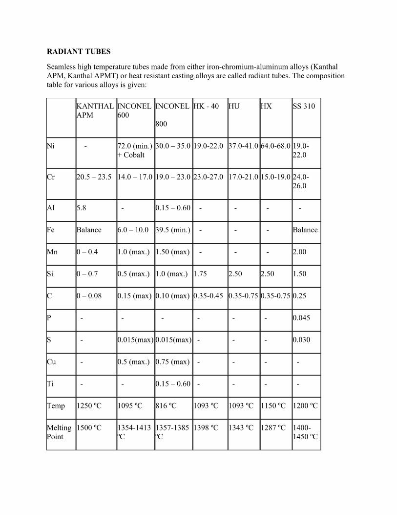
RADIANT TUBES
Seamless high temperature tubes made from either iron-chromium-aluminum alloys (Kanthal
APM, Kanthal APMT) or heat resistant casting alloys are called radiant tubes. The composition
table for various alloys is given:
KANTHAL
APM
INCONEL
600
INCONEL
800
HK - 40 HU HX SS 310
Ni - 72.0 (min.)
+ Cobalt
30.0 – 35.0 19.0-22.0 37.0-41.0 64.0-68.0 19.0-
22.0
Cr 20.5 – 23.5 14.0 – 17.0 19.0 – 23.0 23.0-27.0 17.0-21.0 15.0-19.0 24.0-
26.0
Al 5.8 - 0.15 – 0.60 - - - -
Fe Balance 6.0 – 10.0 39.5 (min.) - - - Balance
Mn 0 – 0.4 1.0 (max.) 1.50 (max) - - - 2.00
Si 0 – 0.7 0.5 (max.) 1.0 (max.) 1.75 2.50 2.50 1.50
C 0 – 0.08 0.15 (max) 0.10 (max) 0.35-0.45 0.35-0.75 0.35-0.75 0.25
P - - - - - - 0.045
S - 0.015(max) 0.015(max) - - - 0.030
Cu - 0.5 (max.) 0.75 (max) - - - -
Ti - - 0.15 – 0.60 - - - -
Temp 1250 ºC 1095 ºC 816 ºC 1093 ºC 1093 ºC 1150 ºC 1200 ºC
Melting
Point
1500 ºC 1354-1413
ºC
1357-1385
ºC
1398 ºC 1343 ºC 1287 ºC 1400-
1450 ºC
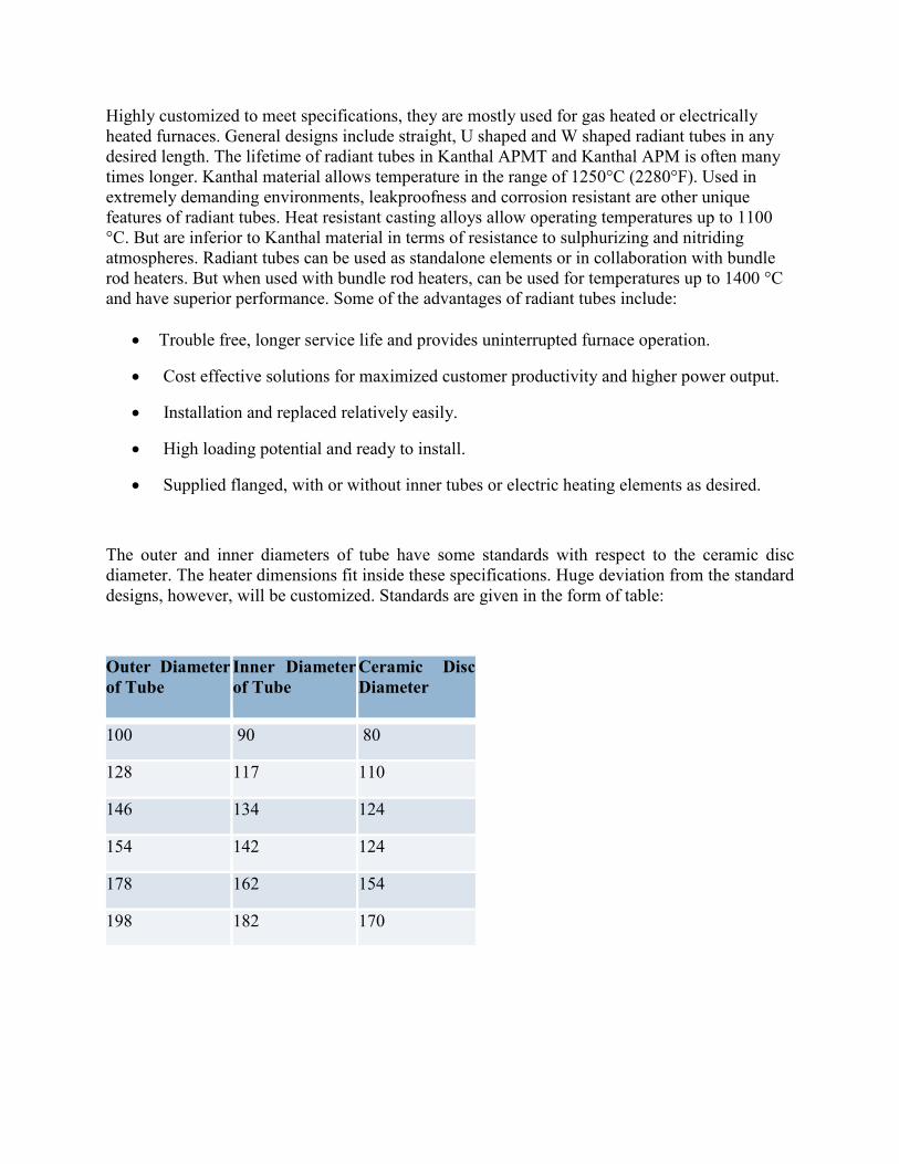
Highly customized to meet specifications, they are mostly used for gas heated or electrically
heated furnaces. General designs include straight, U shaped and W shaped radiant tubes in any
desired length. The lifetime of radiant tubes in Kanthal APMT and Kanthal APM is often many
times longer. Kanthal material allows temperature in the range of 1250°C (2280°F). Used in
extremely demanding environments, leakproofness and corrosion resistant are other unique
features of radiant tubes. Heat resistant casting alloys allow operating temperatures up to 1100
°C. But are inferior to Kanthal material in terms of resistance to sulphurizing and nitriding
atmospheres. Radiant tubes can be used as standalone elements or in collaboration with bundle
rod heaters. But when used with bundle rod heaters, can be used for temperatures up to 1400 °C
and have superior performance. Some of the advantages of radiant tubes include:
• Trouble free, longer service life and provides uninterrupted furnace operation.
• Cost effective solutions for maximized customer productivity and higher power output.
• Installation and replaced relatively easily.
• High loading potential and ready to install.
• Supplied flanged, with or without inner tubes or electric heating elements as desired.
The outer and inner diameters of tube have some standards with respect to the ceramic disc
diameter. The heater dimensions fit inside these specifications. Huge deviation from the standard
designs, however, will be customized. Standards are given in the form of table:
Outer Diameter
of Tube
Inner Diameter
of Tube
Ceramic Disc
Diameter
100 90 80
128 117 110
146 134 124
154 142 124
178 162 154
198 182 170
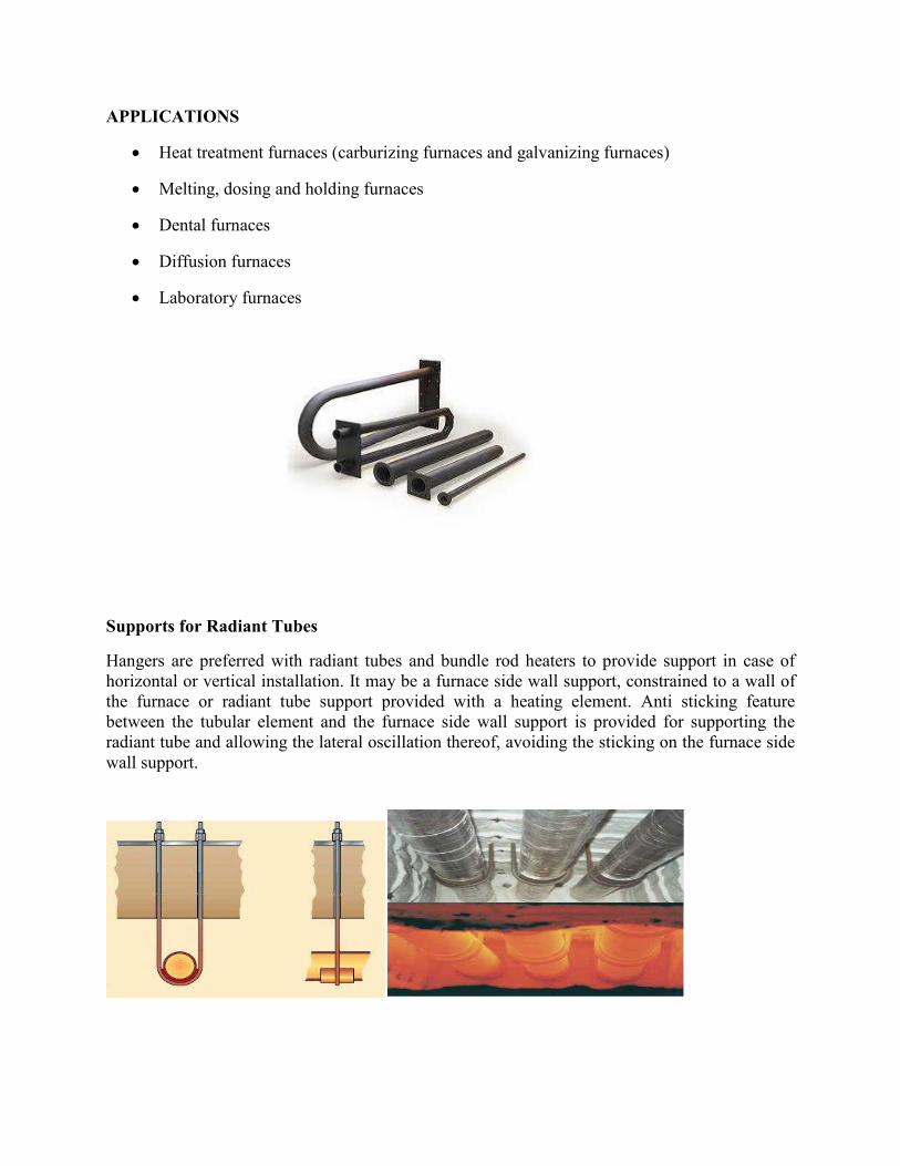
APPLICATIONS
• Heat treatment furnaces (carburizing furnaces and galvanizing furnaces)
• Melting, dosing and holding furnaces
• Dental furnaces
• Diffusion furnaces
• Laboratory furnaces
Supports for Radiant Tubes
Hangers are preferred with radiant tubes and bundle rod heaters to provide support in case of
horizontal or vertical installation. It may be a furnace side wall support, constrained to a wall of
the furnace or radiant tube support provided with a heating element. Anti sticking feature
between the tubular element and the furnace side wall support is provided for supporting the
radiant tube and allowing the lateral oscillation thereof, avoiding the sticking on the furnace side
wall support.
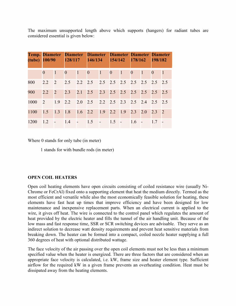
The maximum unsupported length above which supports (hangers) for radiant tubes are
considered essential is given below:
Temp.
(tube)
Diameter
100/90
Diameter
128/117
Diameter
146/134
Diameter
154/142
Diameter
178/162
Diameter
198/182
0 1 0 1 0 1 0 1 0 1 0 1
800 2.2 2 2.5 2.2 2.5 2.5 2.5 2.5 2.5 2.5 2.5 2.5
900 2.2 2 2.3 2.1 2.5 2.3 2.5 2.5 2.5 2.5 2.5 2.5
1000 2 1.9 2.2 2.0 2.5 2.2 2.5 2.3 2.5 2.4 2.5 2.5
1100 1.5 1.3 1.8 1.6 2.2 1.9 2.2 1.9 2.3 2.0 2.3 2
1200 1.2 - 1.4 - 1.5 - 1.5 - 1.6 - 1.7 -
Where 0 stands for only tube (in meter)
1 stands for with bundle rods (in meter)
OPEN COIL HEATERS
Open coil heating elements have open circuits consisting of coiled resistance wire (usually Ni-
Chrome or FeCrAl) fixed onto a supporting element that heat the medium directly. Termed as the
most efficient and versatile while also the most economically feasible solution for heating, these
elements have fast heat up times that improve efficiency and have been designed for low
maintenance and inexpensive replacement parts. When an electrical current is applied to the
wire, it gives off heat. The wire is connected to the control panel which regulates the amount of
heat provided by the electric heater and fills the tunnel of the air handling unit. Because of the
low mass and fast response time, SSR or SCR switching devices are advisable. They serve as an
indirect solution to decrease watt density requirements and prevent heat sensitive materials from
breaking down. The heater can be formed into a compact, coiled nozzle heater supplying a full
360 degrees of heat with optional distributed wattage.
The face velocity of the air passing over the open coil elements must not be less than a minimum
specified value when the heater is energized. There are three factors that are considered when an
appropriate face velocity is calculated, i.e. kW, frame size and heater element type. Sufficient
airflow for the required kW in a given frame prevents an overheating condition. Heat must be
dissipated away from the heating elements.
The following calculation is used for determining face velocity:
Face velocity = CFM/Face Area
Another consideration is the amount of current draw the electric heater will place on the
incoming power source. Electric heaters should be divided into individual circuits drawing 48
amps or less. The amp draw can be calculated using the kW and voltage of the heater.
Amps = (kW x 1000)/ (Vac x 1.732)
Attention must also be paid to the geographical area in which the open coil heater will be
located.
DIFFERENT CONFIGURATIONS
• One, two or four resistance wires
• Parallel coil or straight wire
• Drawn or swaged sheaths
• With or without thermocouples
• Round, rectangular or square cable cross sectionals
Options:
Wire Nichrome or KANTHAL
Rating 4 - 20 kW
Watt Density Up to 75 W/in²
Operating Temperature Up to 650 °C
Length 60 to 320 inches
Outside diameters 1 7/8’’ and 2 ¾’’
Voltage 240 or 480V AC
Controls SSR/ SCR/ Relays/ RTD
Terminations Customized
ADVANTAGES
• High ductility
• Low mass
• Constructed with no open seams
• Available with fittings for mounting
TYPICAL APPLICATIONS
• Plastic injection molding nozzles
• Semiconductor manufacturing and wafer processing
• Hot metal forming dies and punches
• Sealing and cutting bars
• Medical, analytical and scientific instruments
• Restaurant and food processing equipment
• Cast-in heaters
• Laminating and printing presses
• Air heating
• Textile manufacturing
• Heating in a vacuum environment
MINERAL INSULATED HEATER CABLES
Mineral insulated heating cables are series type heating cables and consist of one or two
conductors embedded in a highly dielectric magnesium oxide insulation surrounded by a metal
sheath. High nickel content Alloy 825 is renowned for its use as sheath material in high
temperature applications, and corrosive environments. This alloy has superb resistance to pitting,
chloride stress, and acid and alkali corrosion. Stainless steel can also be used as sheath. Highly
compacted Magnesium Oxide provides insulation of the resistance wire for voltages up to 600V.
Completely sealed sheath protects the MgO from moisture & contamination. MI heating cables
are series-type heating cables and appropriate for temperatures up to 1022°F (550°C) and
exposure temperatures up to 1200°F (650°C). At lower temperatures, watt densities of up to 50
W/Ft can be designed. It provides superior strength in dynamic cut-through, crush, and corrosion
tests and provides rugged and reliable heat tracing for a variety of demanding applications. MI
heating cable sets are supplied factory terminated and ready to install. They include a heating
section and a non heating cold lead section. They are supplied in fixed lengths, so determining
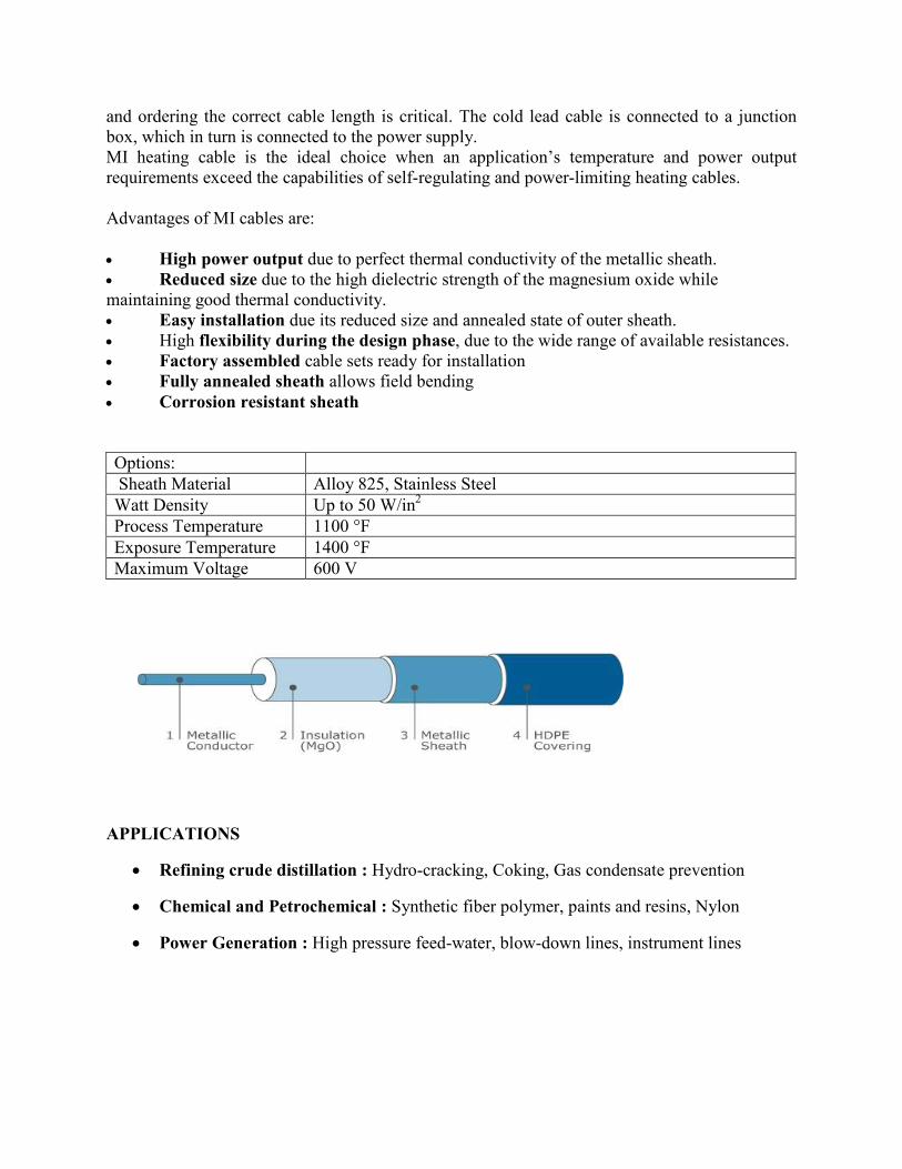
and ordering the correct cable length is critical. The cold lead cable is connected to a junction
box, which in turn is connected to the power supply.
MI heating cable is the ideal choice when an application’s temperature and power output
requirements exceed the capabilities of self-regulating and power-limiting heating cables.
Advantages of MI cables are:
• High power output due to perfect thermal conductivity of the metallic sheath.
• Reduced size due to the high dielectric strength of the magnesium oxide while
maintaining good thermal conductivity.
• Easy installation due its reduced size and annealed state of outer sheath.
• High flexibility during the design phase, due to the wide range of available resistances.
• Factory assembled cable sets ready for installation
• Fully annealed sheath allows field bending
• Corrosion resistant sheath
Options:
Sheath Material Alloy 825, Stainless Steel
Watt Density Up to 50 W/in2
Process Temperature 1100 °F
Exposure Temperature 1400 °F
Maximum Voltage 600 V
APPLICATIONS
• Refining crude distillation : Hydro-cracking, Coking, Gas condensate prevention
• Chemical and Petrochemical : Synthetic fiber polymer, paints and resins, Nylon
• Power Generation : High pressure feed-water, blow-down lines, instrument lines
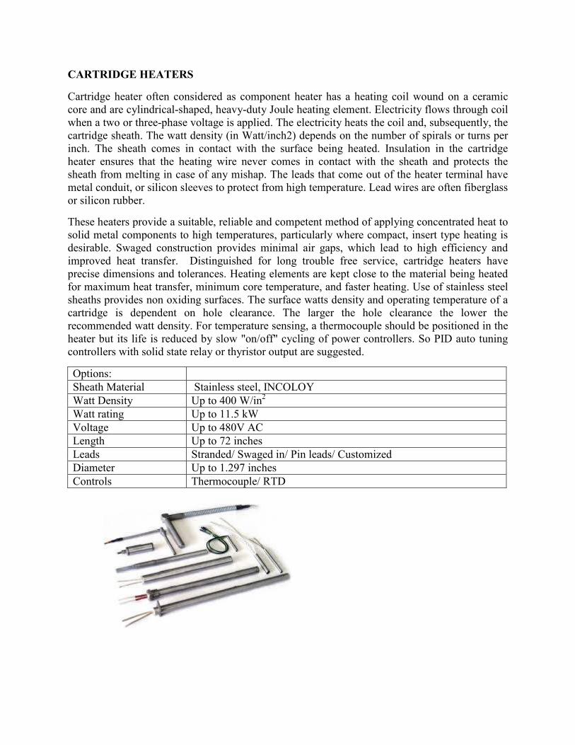
CARTRIDGE HEATERS
Cartridge heater often considered as component heater has a heating coil wound on a ceramic
core and are cylindrical-shaped, heavy-duty Joule heating element. Electricity flows through coil
when a two or three-phase voltage is applied. The electricity heats the coil and, subsequently, the
cartridge sheath. The watt density (in Watt/inch2) depends on the number of spirals or turns per
inch. The sheath comes in contact with the surface being heated. Insulation in the cartridge
heater ensures that the heating wire never comes in contact with the sheath and protects the
sheath from melting in case of any mishap. The leads that come out of the heater terminal have
metal conduit, or silicon sleeves to protect from high temperature. Lead wires are often fiberglass
or silicon rubber.
These heaters provide a suitable, reliable and competent method of applying concentrated heat to
solid metal components to high temperatures, particularly where compact, insert type heating is
desirable. Swaged construction provides minimal air gaps, which lead to high efficiency and
improved heat transfer. Distinguished for long trouble free service, cartridge heaters have
precise dimensions and tolerances. Heating elements are kept close to the material being heated
for maximum heat transfer, minimum core temperature, and faster heating. Use of stainless steel
sheaths provides non oxiding surfaces. The surface watts density and operating temperature of a
cartridge is dependent on hole clearance. The larger the hole clearance the lower the
recommended watt density. For temperature sensing, a thermocouple should be positioned in the
heater but its life is reduced by slow "on/off" cycling of power controllers. So PID auto tuning
controllers with solid state relay or thyristor output are suggested.
Options:
Sheath Material Stainless steel, INCOLOY
Watt Density Up to 400 W/in2
Watt rating Up to 11.5 kW
Voltage Up to 480V AC
Length Up to 72 inches
Leads Stranded/ Swaged in/ Pin leads/ Customized
Diameter Up to 1.297 inches
Controls Thermocouple/ RTD
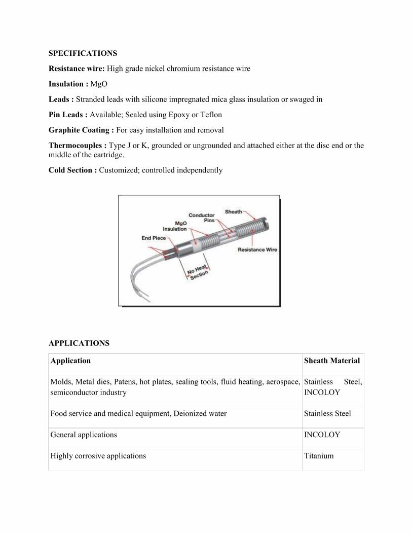
SPECIFICATIONS
Resistance wire: High grade nickel chromium resistance wire
Insulation : MgO
Leads : Stranded leads with silicone impregnated mica glass insulation or swaged in
Pin Leads : Available; Sealed using Epoxy or Teflon
Graphite Coating : For easy installation and removal
Thermocouples : Type J or K, grounded or ungrounded and attached either at the disc end or the
middle of the cartridge.
Cold Section : Customized; controlled independently
APPLICATIONS
Application Sheath Material
Molds, Metal dies, Patens, hot plates, sealing tools, fluid heating, aerospace,
semiconductor industry
Stainless Steel,
INCOLOY
Food service and medical equipment, Deionized water Stainless Steel
General applications INCOLOY
Highly corrosive applications Titanium
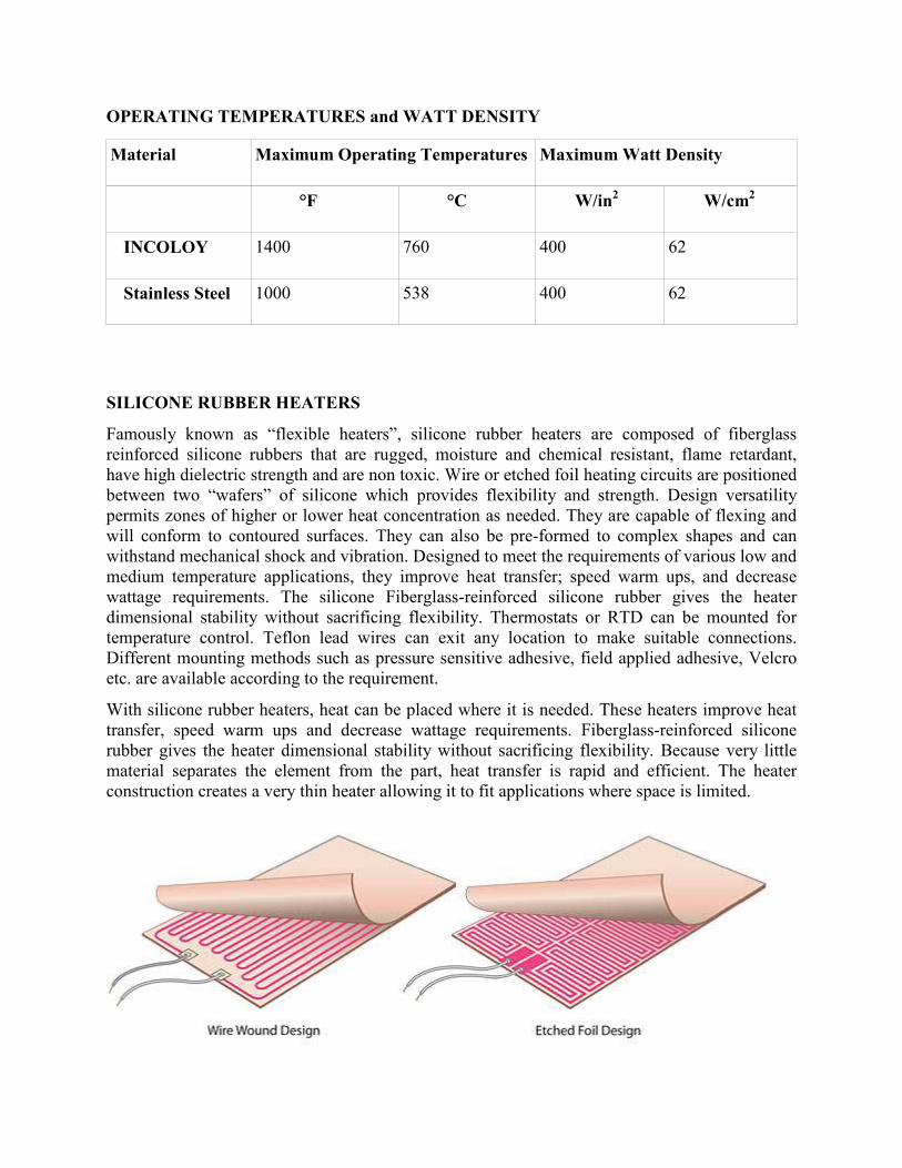
OPERATING TEMPERATURES and WATT DENSITY
Material Maximum Operating Temperatures Maximum Watt Density
°F °C W/in2 W/cm
2
INCOLOY 1400 760 400 62
Stainless Steel 1000 538 400 62
SILICONE RUBBER HEATERS
Famously known as “flexible heaters”, silicone rubber heaters are composed of fiberglass
reinforced silicone rubbers that are rugged, moisture and chemical resistant, flame retardant,
have high dielectric strength and are non toxic. Wire or etched foil heating circuits are positioned
between two “wafers” of silicone which provides flexibility and strength. Design versatility
permits zones of higher or lower heat concentration as needed. They are capable of flexing and
will conform to contoured surfaces. They can also be pre-formed to complex shapes and can
withstand mechanical shock and vibration. Designed to meet the requirements of various low and
medium temperature applications, they improve heat transfer; speed warm ups, and decrease
wattage requirements. The silicone Fiberglass-reinforced silicone rubber gives the heater
dimensional stability without sacrificing flexibility. Thermostats or RTD can be mounted for
temperature control. Teflon lead wires can exit any location to make suitable connections.
Different mounting methods such as pressure sensitive adhesive, field applied adhesive, Velcro
etc. are available according to the requirement.
With silicone rubber heaters, heat can be placed where it is needed. These heaters improve heat
transfer, speed warm ups and decrease wattage requirements. Fiberglass-reinforced silicone
rubber gives the heater dimensional stability without sacrificing flexibility. Because very little
material separates the element from the part, heat transfer is rapid and efficient. The heater
construction creates a very thin heater allowing it to fit applications where space is limited.
Options:
Length 1 to 120 inches
Width 1 to 36 inches
Thickness 0.056" standard, other thicknesses available
Watt Density 80 W/in2
Wattage Tolerance +5, -10%
Operating Temperature -70 to 450 °F
Maximum Temperature 500 °F
Voltage 12V to 600V AC or DC
Lead wire 12 inch Teflon insulated, other types available
FEATURES AND OPTIONS
Dimensions : Maximum38” x 98”
Mounting Methods
• Pressure Sensitive Adhesive Surface (PSAS)
• Silicone contact cement kit
• Field applied adhesive
• Mechanical fasteners
• Factory bonding
Termination Styles
• Teflon Leads
• Silicon Insulated Leads
Construction
• Wire wound
• Etched foil elements
Holes, Cutouts and Notches : Customized
Thermal Insulation : To increase heat efficiency
APPLICATIONS
• Freeze protection and condensation prevention
• Drum Heaters
• Medical equipment
• Computer Peripherals
• Photo processing equipment
• Semiconductor processing equipment
• Shelving
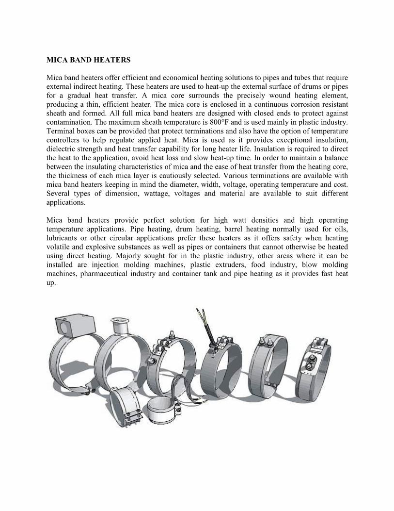
MICA BAND HEATERS
Mica band heaters offer efficient and economical heating solutions to pipes and tubes that require
external indirect heating. These heaters are used to heat-up the external surface of drums or pipes
for a gradual heat transfer. A mica core surrounds the precisely wound heating element,
producing a thin, efficient heater. The mica core is enclosed in a continuous corrosion resistant
sheath and formed. All full mica band heaters are designed with closed ends to protect against
contamination. The maximum sheath temperature is 800°F and is used mainly in plastic industry.
Terminal boxes can be provided that protect terminations and also have the option of temperature
controllers to help regulate applied heat. Mica is used as it provides exceptional insulation,
dielectric strength and heat transfer capability for long heater life. Insulation is required to direct
the heat to the application, avoid heat loss and slow heat-up time. In order to maintain a balance
between the insulating characteristics of mica and the ease of heat transfer from the heating core,
the thickness of each mica layer is cautiously selected. Various terminations are available with
mica band heaters keeping in mind the diameter, width, voltage, operating temperature and cost.
Several types of dimension, wattage, voltages and material are available to suit different
applications.
Mica band heaters provide perfect solution for high watt densities and high operating
temperature applications. Pipe heating, drum heating, barrel heating normally used for oils,
lubricants or other circular applications prefer these heaters as it offers safety when heating
volatile and explosive substances as well as pipes or containers that cannot otherwise be heated
using direct heating. Majorly sought for in the plastic industry, other areas where it can be
installed are injection molding machines, plastic extruders, food industry, blow molding
machines, pharmaceutical industry and container tank and pipe heating as it provides fast heat
up.
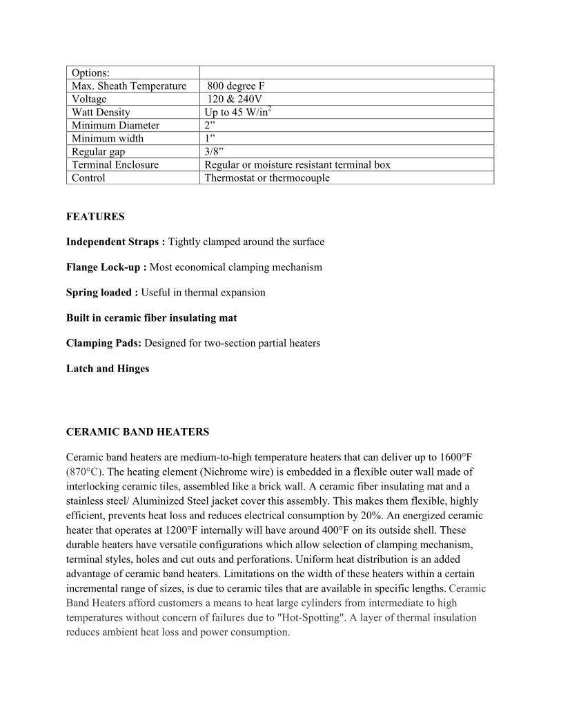
Options:
Max. Sheath Temperature 800 degree F
Voltage 120 & 240V
Watt Density Up to 45 W/in2
Minimum Diameter 2”
Minimum width 1”
Regular gap 3/8”
Terminal Enclosure Regular or moisture resistant terminal box
Control Thermostat or thermocouple
FEATURES
Independent Straps : Tightly clamped around the surface
Flange Lock-up : Most economical clamping mechanism
Spring loaded : Useful in thermal expansion
Built in ceramic fiber insulating mat
Clamping Pads: Designed for two-section partial heaters
Latch and Hinges
CERAMIC BAND HEATERS
Ceramic band heaters are medium-to-high temperature heaters that can deliver up to 1600°F
(870°C). The heating element (Nichrome wire) is embedded in a flexible outer wall made of
interlocking ceramic tiles, assembled like a brick wall. A ceramic fiber insulating mat and a
stainless steel/ Aluminized Steel jacket cover this assembly. This makes them flexible, highly
efficient, prevents heat loss and reduces electrical consumption by 20%. An energized ceramic
heater that operates at 1200°F internally will have around 400°F on its outside shell. These
durable heaters have versatile configurations which allow selection of clamping mechanism,
terminal styles, holes and cut outs and perforations. Uniform heat distribution is an added
advantage of ceramic band heaters. Limitations on the width of these heaters within a certain
incremental range of sizes, is due to ceramic tiles that are available in specific lengths. Ceramic
Band Heaters afford customers a means to heat large cylinders from intermediate to high
temperatures without concern of failures due to "Hot-Spotting". A layer of thermal insulation
reduces ambient heat loss and power consumption.
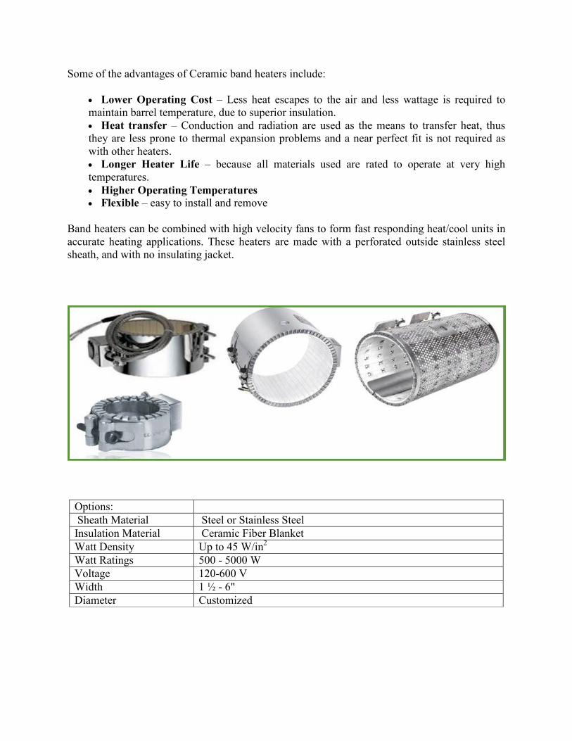
Some of the advantages of Ceramic band heaters include:
• Lower Operating Cost – Less heat escapes to the air and less wattage is required to
maintain barrel temperature, due to superior insulation.
• Heat transfer – Conduction and radiation are used as the means to transfer heat, thus
they are less prone to thermal expansion problems and a near perfect fit is not required as
with other heaters.
• Longer Heater Life – because all materials used are rated to operate at very high
temperatures.
• Higher Operating Temperatures
• Flexible – easy to install and remove
Band heaters can be combined with high velocity fans to form fast responding heat/cool units in
accurate heating applications. These heaters are made with a perforated outside stainless steel
sheath, and with no insulating jacket.
Options:
Sheath Material Steel or Stainless Steel
Insulation Material Ceramic Fiber Blanket
Watt Density Up to 45 W/in2
Watt Ratings 500 - 5000 W
Voltage 120-600 V
Width 1 ½ - 6"
Diameter Customized
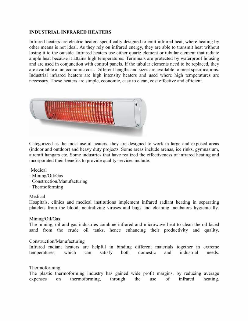
INDUSTRIAL INFRARED HEATERS
Infrared heaters are electric heaters specifically designed to emit infrared heat, where heating by
other means is not ideal. As they rely on infrared energy, they are able to transmit heat without
losing it to the outside. Infrared heaters use either quartz element or tubular element that radiate
ample heat because it attains high temperatures. Terminals are protected by waterproof housing
and are used in conjunction with control panels. If the tubular elements need to be replaced, they
are available at an economic cost. Different lengths and sizes are available to meet specifications.
Industrial infrared heaters are high intensity heaters and used where high temperatures are
necessary. These heaters are simple, economic, easy to clean, cost effective and efficient.
Categorized as the most useful heaters, they are designed to work in large and exposed areas
(indoor and outdoor) and heavy duty projects. Some areas include arenas, ice rinks, gymnasium,
aircraft hangars etc. Some industries that have realized the effectiveness of infrared heating and
incorporated their benefits to provide quality services include:
·Medical
· Mining/Oil/Gas
· Construction/Manufacturing
· Thermoforming
Medical
Hospitals, clinics and medical institutions implement infrared radiant heating in separating
platelets from the blood, neutralizing viruses and bugs and cleaning incubators hygienically.
Mining/Oil/Gas
The mining, oil and gas industries combine infrared and microwave heat to clean the oil laced
sand from the crude oil tanks, hence enhancing their productivity and quality.
Construction/Manufacturing
Infrared radiant heaters are helpful in binding different materials together in extreme
temperatures, which can satisfy both domestic and industrial needs.
Thermoforming
The plastic thermoforming industry has gained wide profit margins, by reducing average
expenses on thermoforming, through the use of infrared heating.
APPLICATION CONSTRUCTION TYPE FEATURES
Conveyorised or batch type ovens
Drying
Curing
Single tubular element
(Type 1)
The mineral insulated alloy
sheath heating element prevents
splashing and vibration and
provides a longer service life
than other source types.
De-greasing, Weld preheating,
Roll heating,
Drying, Sterilization
Double tubular element
(Type 2)
Two series wired heating
elements in
Reflectors
Outdoor installations
Wash-down exposed areas
Hairpin tubular element with
moisture resistant terminal
housing
(Type 3)
N/A
Industrial applications with
medium intensity infrared heat:
Paint spray, Booths, Curing,
Drying Softening resins, Vinyl
and Plastics
Quartz tube (Type 4)
Horizontal mounting for tube
fixtures
High intensity heat applications Double quartz tube elements
(Type 5)
Horizontal mounting for tube
fixtures
High intensity radiation, on/off
heating:
Baking, Drying, Curing
(paint, varnishes, lacquers,
adhesives, softening plastics, food
processing)
Quartz lamp element (Type
6)
Horizontal mounting for tube
fixtures
EDGE WOUND HEATERS
Edge wound elements are used in applications where utmost power is required in limited space.
These elements replace rod elements in furnaces requiring more power and are used to convert
gas-fired furnaces to electric heating. Different furnaces such as roller hearth, pit, batch, low
temperature aluminum tempering furnaces and high temperature exothermic gas generators use
these heating elements to meet their heating requirement. A nickel-chromium alloy (80/20 or
70/20) forms the basis of these heaters. Dimensions are custom made to suit high temperature
and high power ratings. Benefits include:
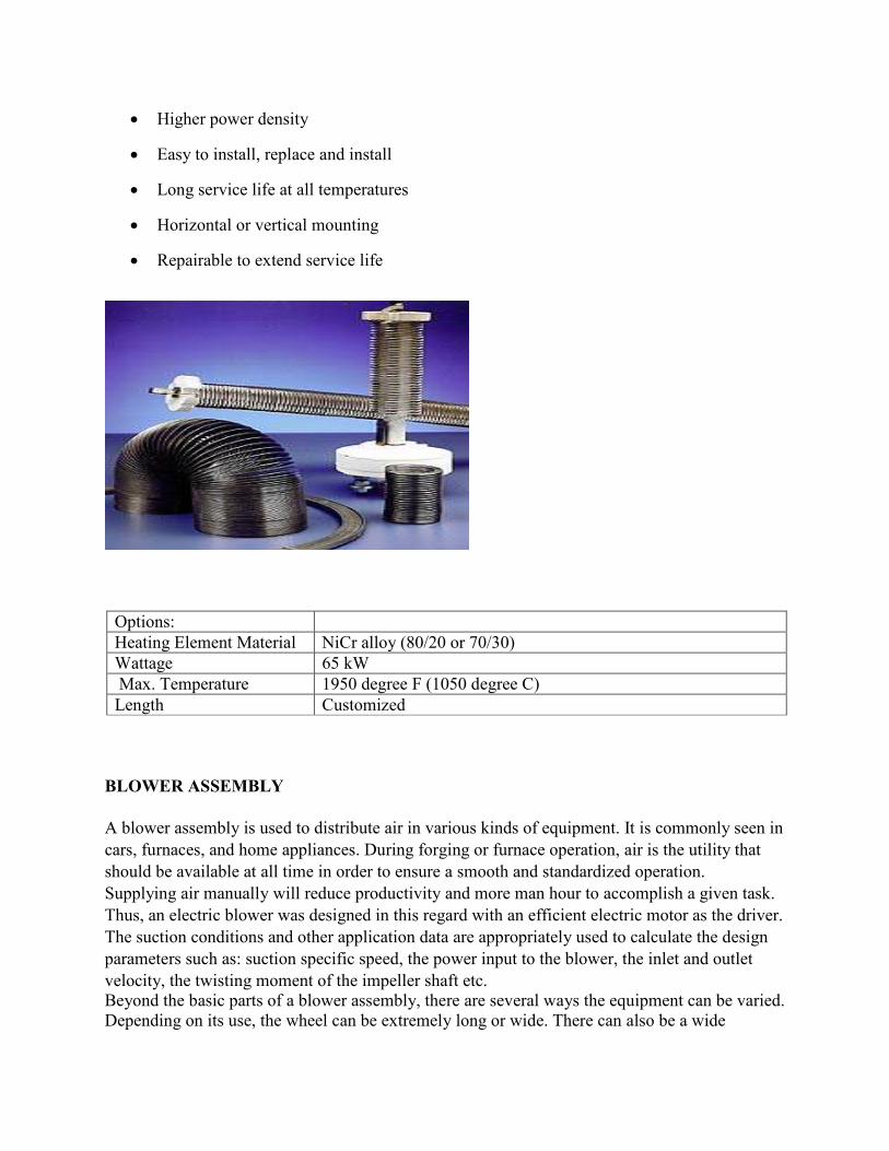
• Higher power density
• Easy to install, replace and install
• Long service life at all temperatures
• Horizontal or vertical mounting
• Repairable to extend service life
Options:
Heating Element Material NiCr alloy (80/20 or 70/30)
Wattage 65 kW
Max. Temperature 1950 degree F (1050 degree C)
Length Customized
BLOWER ASSEMBLY
A blower assembly is used to distribute air in various kinds of equipment. It is commonly seen in
cars, furnaces, and home appliances. During forging or furnace operation, air is the utility that
should be available at all time in order to ensure a smooth and standardized operation.
Supplying air manually will reduce productivity and more man hour to accomplish a given task.
Thus, an electric blower was designed in this regard with an efficient electric motor as the driver.
The suction conditions and other application data are appropriately used to calculate the design
parameters such as: suction specific speed, the power input to the blower, the inlet and outlet
velocity, the twisting moment of the impeller shaft etc.
Beyond the basic parts of a blower assembly, there are several ways the equipment can be varied.
Depending on its use, the wheel can be extremely long or wide. There can also be a wide
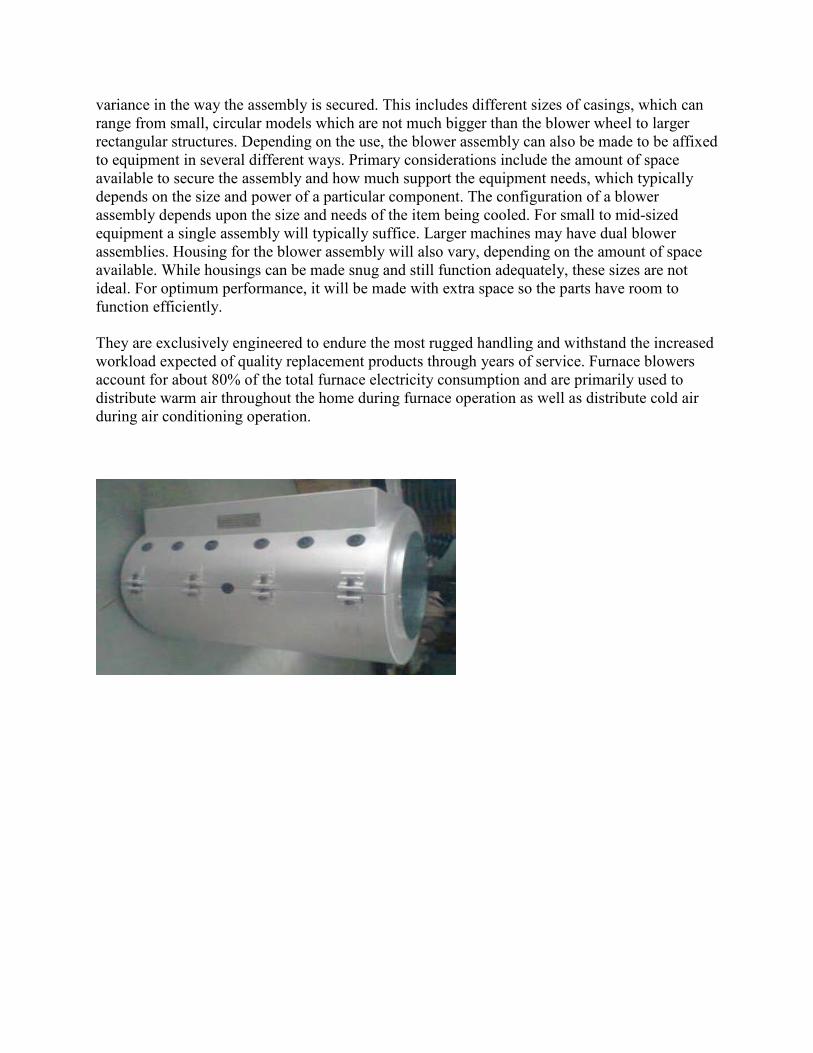
variance in the way the assembly is secured. This includes different sizes of casings, which can
range from small, circular models which are not much bigger than the blower wheel to larger
rectangular structures. Depending on the use, the blower assembly can also be made to be affixed
to equipment in several different ways. Primary considerations include the amount of space
available to secure the assembly and how much support the equipment needs, which typically
depends on the size and power of a particular component. The configuration of a blower
assembly depends upon the size and needs of the item being cooled. For small to mid-sized
equipment a single assembly will typically suffice. Larger machines may have dual blower
assemblies. Housing for the blower assembly will also vary, depending on the amount of space
available. While housings can be made snug and still function adequately, these sizes are not
ideal. For optimum performance, it will be made with extra space so the parts have room to
function efficiently.
They are exclusively engineered to endure the most rugged handling and withstand the increased
workload expected of quality replacement products through years of service. Furnace blowers
account for about 80% of the total furnace electricity consumption and are primarily used to
distribute warm air throughout the home during furnace operation as well as distribute cold air
during air conditioning operation.