10 led mono vu meter - velleman.eu · 4 1.3 soldering hints : 1-assembly hints mount the component...
TRANSCRIPT
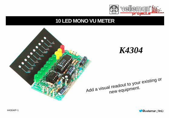
K4304
H4304IP-1
Add a visual readout to your existing or
new equipment.
10 LED MONO VU METER
2
Features:
For instant visualization of audio signal levels. Easy hook up to a LINE level ( LOW input) signal source. For use with mixing panels, amplifiers, CD players, radio’s, ... A special input (HIGH INPUT) is provided, which allows direct connection to a SPEAKER output . DOT or BAR display mode selectable to suit your application. Attractive display window supplied, which can be used both horizontal as vertical. If wanted, the unit can be calibrated by means of a trim potentiometer. Specifications:
1 X 10 LED’s Bar or dot mode. Indication range : 0dB = 0.775mVrms.
-20dB, -10dB, -7dB, -5dB, -3dB, -1dB, 0dB, +1dB, +2dB, +3dB Frequency range : 20Hz to 30KHz Low input for 0dB: 150mV to 6Vrms (47K) High input for 0dB: 1.5V to 60Vrms (470K). Power supply : 10 to 15VDC / 110mA max. PCB Dimensions : 68X37mm
NOT SUITED FOR CONNECTION TO HIGH POWER CAR STEREO SYSTEM
Features & Specifications
3
Assembly hints
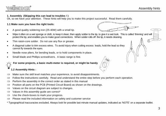
1. Assembly (Skipping this can lead to troubles ! ) Ok, so we have your attention. These hints will help you to make this project successful. Read them carefully. 1.1 Make sure you have the right tools: A good quality soldering iron (25-40W) with a small tip.
Wipe it often on a wet sponge or cloth, to keep it clean; then apply solder to the tip, to give it a wet look. This is called ‘thinning’ and will protect the tip, and enables you to make good connections. When solder rolls off the tip, it needs cleaning.
Thin raisin-core solder. Do not use any flux or grease.
A diagonal cutter to trim excess wires. To avoid injury when cutting excess leads, hold the lead so they cannot fly towards the eyes.
Needle nose pliers, for bending leads, or to hold components in place.
Small blade and Phillips screwdrivers. A basic range is fine.
For some projects, a basic multi-meter is required, or might be handy
1.2 Assembly Hints :
Make sure the skill level matches your experience, to avoid disappointments. Follow the instructions carefully. Read and understand the entire step before you perform each operation. Perform the assembly in the correct order as stated in this manual Position all parts on the PCB (Printed Circuit Board) as shown on the drawings. Values on the circuit diagram are subject to changes. Values in this assembly guide are correct* Use the check-boxes to mark your progress. Please read the included information on safety and customer service
* Typographical inaccuracies excluded. Always look for possible last minute manual updates, indicated as ‘NOTE’ on a separate leaflet.
0.000
4
Assembly hints
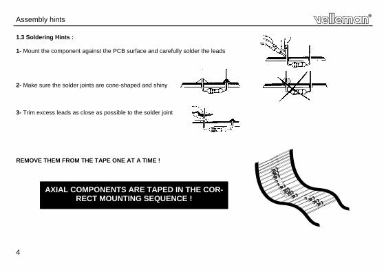
1.3 Soldering Hints :
1- Mount the component against the PCB surface and carefully solder the leads
2- Make sure the solder joints are cone-shaped and shiny
3- Trim excess leads as close as possible to the solder joint
REMOVE THEM FROM THE TAPE ONE AT A TIME !
AXIAL COMPONENTS ARE TAPED IN THE COR-RECT MOUNTING SEQUENCE !
5
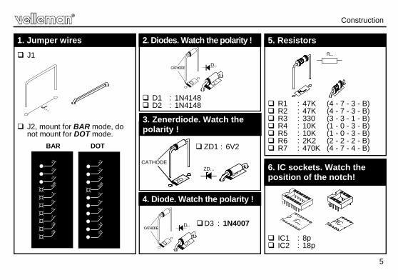
Construction
D1 : 1N4148 D2 : 1N4148
2. Diodes. Watch the polarity !
D...CATHODE
ZD1 : 6V2
3. Zenerdiode. Watch the polarity !
R1 : 47K (4 - 7 - 3 - B) R2 : 47K (4 - 7 - 3 - B) R3 : 330 (3 - 3 - 1 - B) R4 : 10K (1 - 0 - 3 - B) R5 : 10K (1 - 0 - 3 - B) R6 : 2K2 (2 - 2 - 2 - B) R7 : 470K (4 - 7 - 4 - B)
5. Resistors R...
CATHODEZD...
IC1 : 8p IC2 : 18p
6. IC sockets. Watch the position of the notch!
J1
J2, mount for BAR mode, do not mount for DOT mode.
1. Jumper wires +3 +3
+2 +2
+1 +1
0dB
0dB
-1 -1
-3 -3
-5 -5
-7 -7
-10 -10
-20 -20
BAR DOT
D3 : 1N4007
4. Diode. Watch the polarity !
D...CATHODE
6
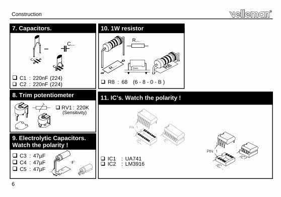
IC1 : UA741 IC2 : LM3916
Construction
C1 : 220nF (224) C2 : 220nF (224)
7. Capacitors.
11. IC’s. Watch the polarity !
C...
R8 : 68 (6 - 8 - 0 - B )
10. 1W resistor
R...
2mm
RV1 : 220K (Sensitivity)
8. Trim potentiometer
C3 : 47µF C4 : 47µF C5 : 47µF
9. Electrolytic Capacitors. Watch the polarity !
C...
-
7
Construction
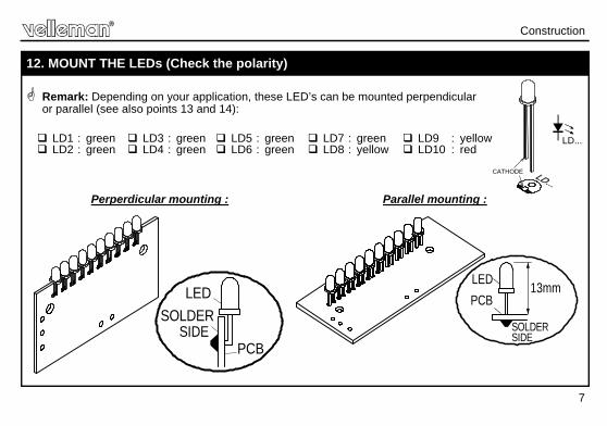
Remark: Depending on your application, these LED’s can be mounted perpendicular
or parallel (see also points 13 and 14):
Perperdicular mounting : Parallel mounting :
12. MOUNT THE LEDs (Check the polarity)
PCB
SOLDERSIDE
LED 13mm
SOLDER
PCB
SIDE
LED
LD1 : green LD2 : green
LD3 : green LD4 : green
LD5 : green LD6 : green
LD7 : green LD8 : yellow
LD9 : yellow LD10 : red
LD...
CATHODE
8
Ø3.5
5260
7
4.5
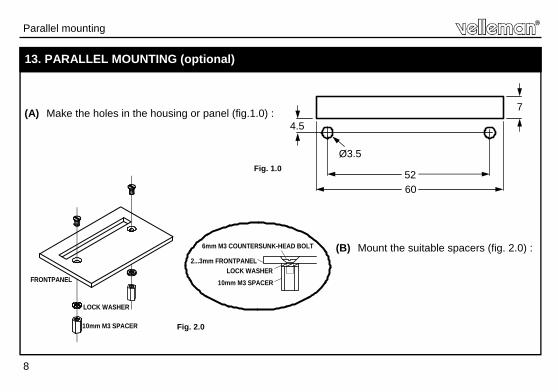
Parallel mounting
13. PARALLEL MOUNTING (optional) (A) Make the holes in the housing or panel (fig.1.0) :
(B) Mount the suitable spacers (fig. 2.0) : 6mm M3 COUNTERSUNK-HEAD BOLT
LOCK WASHER
10mm M3 SPACER
FRONTPANEL
2...3mm FRONTPANEL
10mm M3 SPACERLOCK WASHER
Fig. 2.0
Fig. 1.0

9
6mm M3 COUNTERSUNK-HEAD BOLT
4mm M3 BOLT
2...3mm FRONTPANEL
10mm M3 SPACER
4mm M3 BOLT
PCB
LOCK WASHER
(C) Mount the PCB onto the spacers (fig 3.0) :
Fig. 3.0
Parallel mounting
10
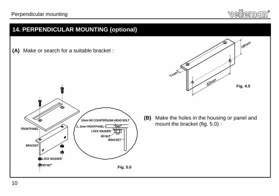
14. PERPENDICULAR MOUNTING (optional)
Fig. 4.0
(A) Make or search for a suitable bracket :
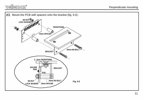
(B) Make the holes in the housing or panel and mount the bracket (fig. 5.0) :
Fig. 5.0
Perpendicular mounting
LOCK WASHERM3 NUT
10mm M3 COUNTERSUNK-HEAD BOLT
BRACKET
FRONTPANEL
LOCK WASHER
M3 NUT
2...3mm FRONTPANEL
BRACKET
11
15mm SPACER
2...3mm FRONTPANEL
PCB
M3 NUTLOCK WASHER
SOLDERSIDE
20mm M3 BOLT
20mm M3 BOLT
BRACKET
BRACKET
15mm SPACER
LOCK WASHERM3 NUT
FRONTPANEL
(C) Mount the PCB with spacers onto the bracket (fig. 6.0) :
Fig. 6.0
Perpendicular mounting
12
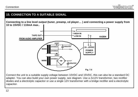
15. CONNECTION TO A SUITABLE SIGNAL Connecting to a line level output (tuner, preamp, cd player… ) and connecting a power supply from 10 to 15VDC / 110mA max..
Connect the unit to a suitable supply voltage between 10VDC and 15VDC, this can also be a standard DC adapter. You can also build your own power supply, see diagram. Use a 2x12V transformer, two rectifier diodes and a electrolytic capacitor or use a single 12V transformer with a bridge rectifier and a electrolytic capacitor.
Fig. 7.0
Connection
12V/150mA
12V/150mA
12V/150mAMAINS
MAINS
FROM AUDIO AMPLIFIERTAPE OUT
10...15VDC
1000uF/25V+
1000uF/25V
1N4007
1N4007+
SUPPLYPOWER
+
HIGH INLOW IN + K4304
13
12V/150mA
12V/150mA
12V/150mA
FROM POWER AMPLIFIER
MAINS
MAINS
SPEAKER OUT-+INPUT (0)
10...15VDC
1000uF/25V
1N4007
+
1000uF/25V
1N4007+
POWERSUPPLY
+
LOW INHIGH IN
+ K4304
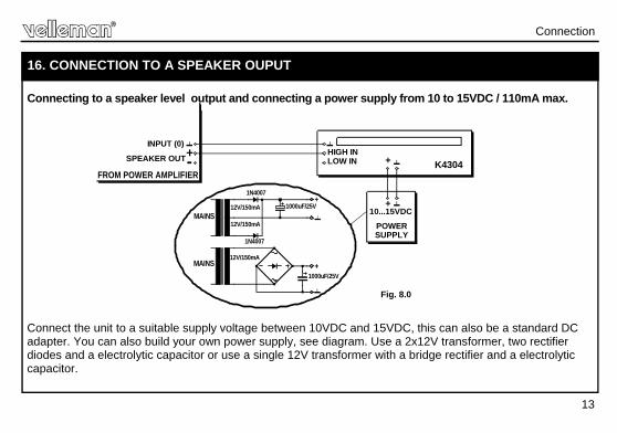
16. CONNECTION TO A SPEAKER OUPUT Connecting to a speaker level output and connecting a power supply from 10 to 15VDC / 110mA max.
Connect the unit to a suitable supply voltage between 10VDC and 15VDC, this can also be a standard DC adapter. You can also build your own power supply, see diagram. Use a 2x12V transformer, two rectifier diodes and a electrolytic capacitor or use a single 12V transformer with a bridge rectifier and a electrolytic capacitor.
Fig. 8.0
Connection
14
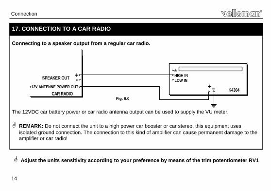
17. CONNECTION TO A CAR RADIO Connecting to a speaker output from a regular car radio.
The 12VDC car battery power or car radio antenna output can be used to supply the VU meter. REMARK: Do not connect the unit to a high power car booster or car stereo, this equipment uses
isolated ground connection. The connection to this kind of amplifier can cause permanent damage to the amplifier or car radio!
Fig. 9.0
Connection
-+12V ANTENNE POWER OUT
CAR RADIO
SPEAKER OUT +LOW IN
+ K4304
HIGH IN
Adjust the units sensitivity according to your preference by means of the trim potentiometer RV1
15
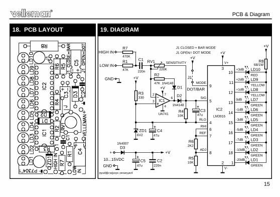
18. PCB LAYOUT
PCB & Diagram
LOW IN
GND
C1
220n
R1
47K
RV1
220K
R2
47K
UA741
IC1
+V
2
3
4
76
D11N4148
D2
1N4148
R3330
+V
R410K
C347u
6V2ZD1 C4
47u
5
4
SIG
RLO
6RHI
REF7
R62K2
R510K
ADJ8
J1
DOT/BAR
+V
9MODE
+V
3
2
V+
V-
LD2GREEN
18-10dB
LD3GREEN
-7dB17
LD4GREEN
-5dB16
LD5GREEN
-3dB15
LD6GREEN
-1dB14
LD7GREEN
0dB13
LD8YELLOW
+1dB12
LD9YELLOW
+2dB11
LD10RED
+3dB10
LD1GREEN
-20dB1
R868/1W
+V
+
GND
D31N4007
C547u
C2220n
+V
IC2
LM3916
10...15VDC
R7
470KHIGH IN
J1 CLOSED = BAR MODE
J1 OPEN= DOT MODE
SENSITIVITY
modifications reserved
19. DIAGRAM
5 4 1 0 3 2 9 2 8 9 8 9 8
Modifications and typographical errors reserved © Velleman nv. H4304IP’1 - 2014 (rev1)
VELLEMAN NV Legen Heirweg 33, B-9890 GAVERE
Belgium (Europe)