1. terrestrial antennas en - icp.rs filethe uhf section is a triple yagi antenna consisting of an...
TRANSCRIPT

TERRESTRIAL ANTENNAS
TERRESTRIAL ANTENNAS
6 Catalogue 2013 / 2014
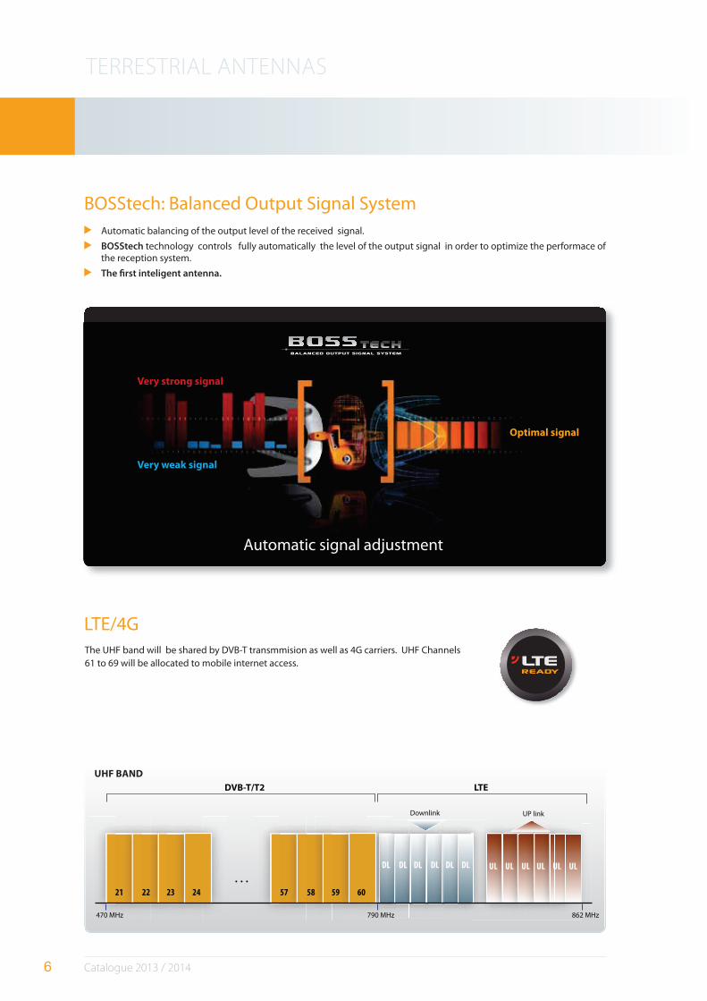
BOSStech: Balanced Output Signal System
LTE/4G
Automatic balancing of the output level of the received signal.
BOSStech technology controls fully automatically the level of the output signal in order to optimize the performace of the reception system.
The "rst inteligent antenna.
Very strong signal
Very weak signal
Optimal signal
Automatic signal adjustment
The UHF band will be shared by DVB-T transmmision as well as 4G carriers. UHF Channels 61 to 69 will be allocated to mobile internet access.
470 MHz 790 MHz
Downlink UP link
862 MHz
DVB-T/T2 LTE
21 22 23 24 57 58 59 60
. . .
DL DL DL DL DL DL UL UL UL UL UL UL
UHF BAND
TERRESTRIAL ANTENNAS
7 Catalogue 2013 / 2014
BOSS ANTENNAS
Reference 149610 / 149611 149401 / 149402
Operating mode BOSS OFF BOSS ON BOSS OFF BOSS ON
Channels 5-12 21-69 5-12 21-69 5-12 21-60 5-12 21-60
Gain dBi 8,5 16 21 28 max 8,5 16 21 31 max
Output level dBµV – Auto – Auto
Noise #gure dB – 2 – 2
Powering voltage Vdc
0 12...24 0 12...24
Consumption mA – 40 – 40
Length mm 1112 1200
Wind load800 N/m2
N135 120
1100 N/m2 185 165
REF. DESCRIPTION
149401 DAT HD BOSS MIX 790 (single pack)
149402 DAT HD BOSS MIX 790 (5 units/pack)
149610 DAT HD BOSS MIX (4 units/pack)
149611 DAT HD BOSS MIX (single pack)
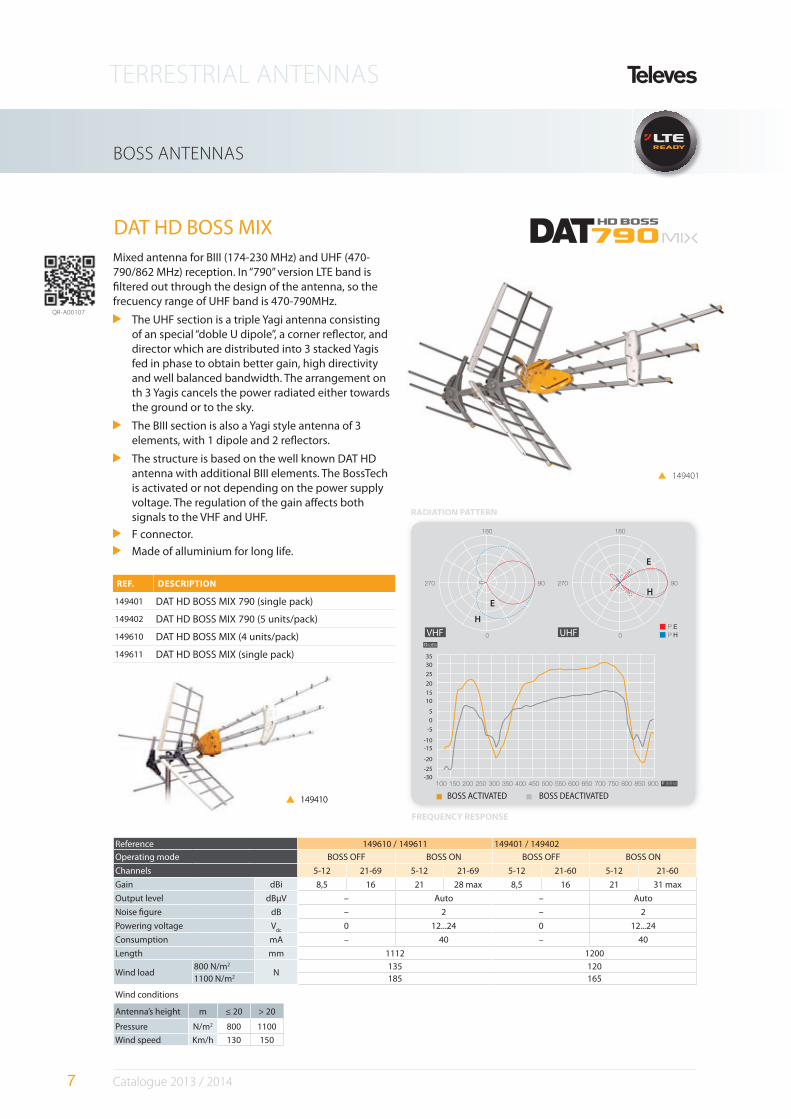
DAT HD BOSS MIX
FREQUENCY RESPONSE
RADIATION PATTERN
Mixed antenna for BIII (174-230 MHz) and UHF (470-790/862 MHz) reception. In “790” version LTE band is #ltered out through the design of the antenna, so the frecuency range of UHF band is 470-790MHz.
The UHF section is a triple Yagi antenna consisting of an special “doble U dipole”, a corner re$ector, and director which are distributed into 3 stacked Yagis fed in phase to obtain better gain, high directivity and well balanced bandwidth. The arrangement on th 3 Yagis cancels the power radiated either towards the ground or to the sky.
The BIII section is also a Yagi style antenna of 3 elements, with 1 dipole and 2 re$ectors.
The structure is based on the well known DAT HD antenna with additional BIII elements. The BossTech is activated or not depending on the power supply voltage. The regulation of the gain a%ects both signals to the VHF and UHF.
F connector.
Made of alluminium for long life.
QR-A00107
Wind conditions
Antenna’s height m ≤ 20 > 20
Pressure N/m2 800 1100
Wind speed Km/h 130 150
RADIATION PATT
UHFVHF
(dBi)
-25
-30
-20
-15
-10
-5
0
5
10
15
20
25
30
35
E
E
H
H
149401
149410 149410 BOSS ACTIVATED BOSS DEACTIVATED
TERRESTRIAL ANTENNAS
8 Catalogue 2013 / 2014
Reference 149901/02 1495 / 149501
BOSStech OFF ON OFF ON
Channels 21-60 21-69
Max Gain dBi 17 32 17 29
Output level dBµV – Auto – Auto
Noise #gure dB – 2 – 2
Recommended output level dBµV > 75 < 75 > 75 < 75
Power supply Vdc
0 12...24 0 12...24
Maximum current mA - 40 – 40
Beamwidth º 30 30
Length mm 1112 1112
Wind load800 N/m2
N120 120
1100 N/m2 165 165
Wind conditions
Antenna’s height m ≤ 20 > 20
Pressure N/m2 800 1100
Wind speed Km/h 130 150
BOSS ANTENNAS
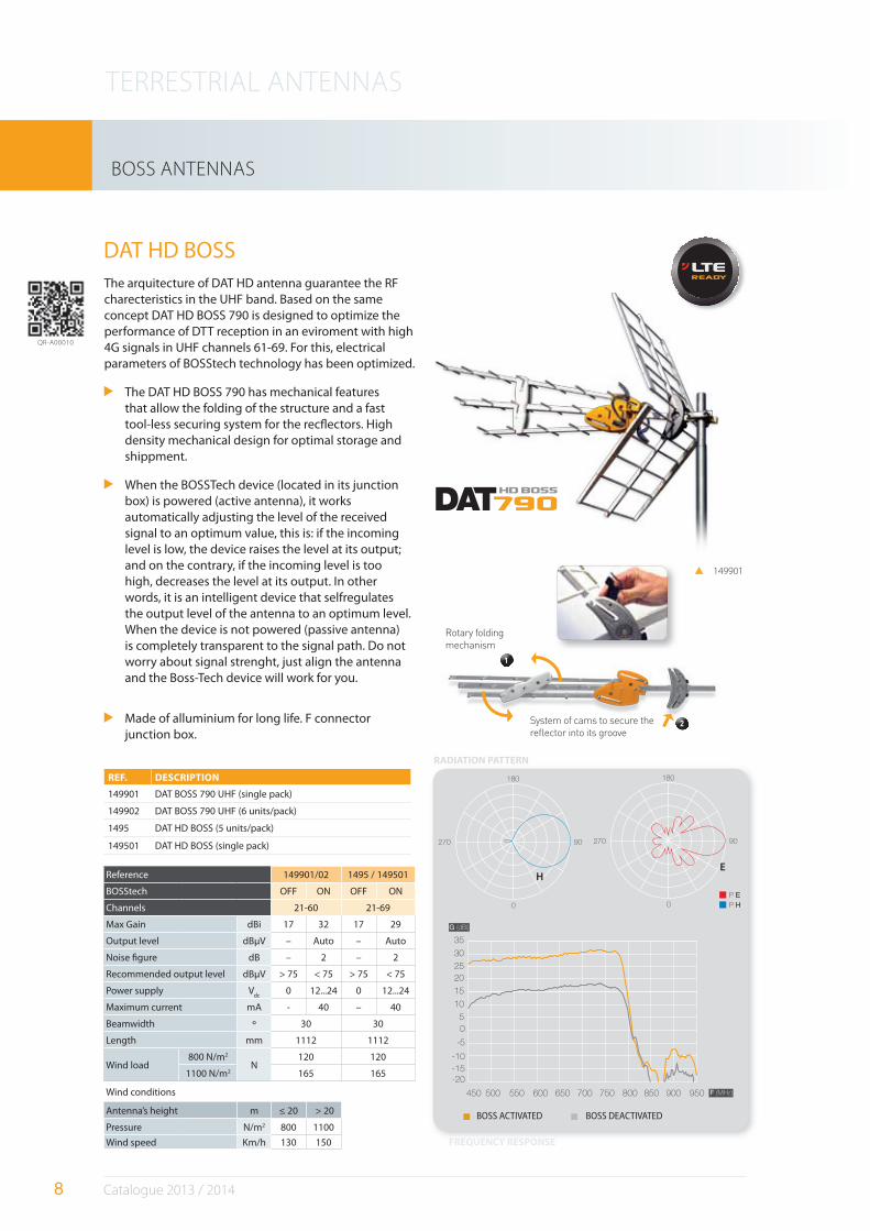
The arquitecture of DAT HD antenna guarantee the RF charecteristics in the UHF band. Based on the same concept DAT HD BOSS 790 is designed to optimize the performance of DTT reception in an eviroment with high 4G signals in UHF channels 61-69. For this, electrical parameters of BOSStech technology has been optimized.
The DAT HD BOSS 790 has mechanical features that allow the folding of the structure and a fast tool-less securing system for the rec$ectors. High density mechanical design for optimal storage and shippment.
When the BOSSTech device (located in its junction box) is powered (active antenna), it works automatically adjusting the level of the received signal to an optimum value, this is: if the incoming level is low, the device raises the level at its output; and on the contrary, if the incoming level is too high, decreases the level at its output. In other words, it is an intelligent device that selfregulates the output level of the antenna to an optimum level. When the device is not powered (passive antenna) is completely transparent to the signal path. Do not worry about signal strenght, just align the antenna and the Boss-Tech device will work for you.
Made of alluminium for long life. F connector junction box.
REF. DESCRIPTION
149901 DAT BOSS 790 UHF (single pack)
149902 DAT BOSS 790 UHF (6 units/pack)
1495 DAT HD BOSS (5 units/pack)
149501 DAT HD BOSS (single pack)
DAT HD BOSS
149901
270 90
180
0
270 90
180
0
900 950 F (MHz)
G (dBi)
35
850800750700650600550500450
10
15
20
25
30
-15
-20
-10
-5
0
5
EH
FREQUENCY RESPONSE
RADIATION PATTERN
BOSS ACTIVATED BOSS DEACTIVATED
QR-A00010
1
2
Rotary folding
mechanism
System of cams to secure the
reflector into its groove
TERRESTRIAL ANTENNAS
9 Catalogue 2013 / 2014
BOSS ANTENNAS
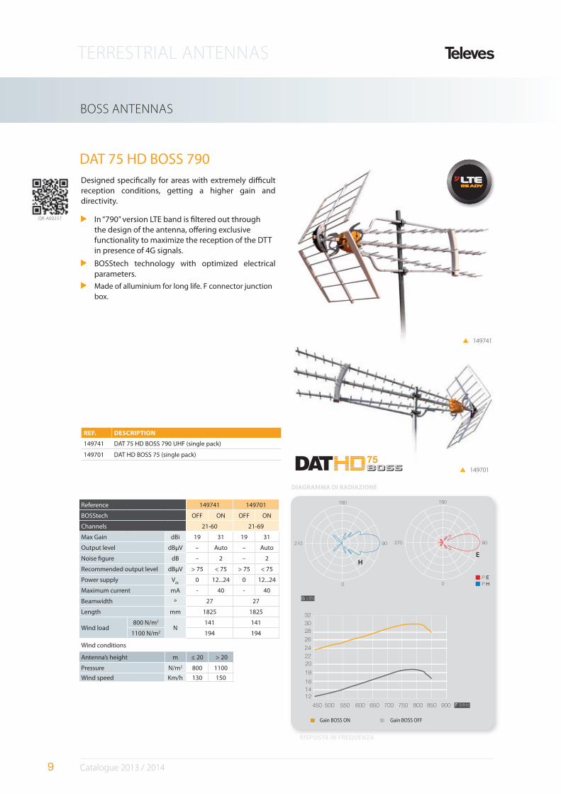
Designed speci#cally for areas with extremely di*cult reception conditions, getting a higher gain and directivity.
In “790” version LTE band is #ltered out through the design of the antenna, o%ering exclusive functionality to maximize the reception of the DTT in presence of 4G signals.
BOSStech technology with optimized electrical parameters.
Made of alluminium for long life. F connector junction box.
REF. DESCRIPTION
149741 DAT 75 HD BOSS 790 UHF (single pack)
149701 DAT HD BOSS 75 (single pack)
DAT 75 HD BOSS 790
270 90
180
0
270 90
180
0
900 F (MHz)
G (dBi)
850800750700650600550500450
24
26
28
30
32
14
12
16
18
20
22
EH
RISPOSTA IN FREQUENZA
DIAGRAMMA DI RADIAZIONE
Gain BOSS ON Gain BOSS OFF
QR-A00257
149741
Reference 149741 149701
BOSStech OFF ON OFF ON
Channels 21-60 21-69
Max Gain dBi 19 31 19 31
Output level dBµV – Auto – Auto
Noise #gure dB – 2 – 2
Recommended output level dBµV > 75 < 75 > 75 < 75
Power supply Vdc
0 12...24 0 12...24
Maximum current mA - 40 - 40
Beamwidth º 27 27
Length mm 1825 1825
Wind load800 N/m2
N141 141
1100 N/m2 194 194
Wind conditions
Antenna’s height m ≤ 20 > 20
Pressure N/m2 800 1100
Wind speed Km/h 130 150
149701
TERRESTRIAL ANTENNAS
10 Catalogue 2013 / 2014
BOSS ANTENNAS
5605 5605
561901 / 562001
Vdc
System without Q-BOSS System with Q-BOSS
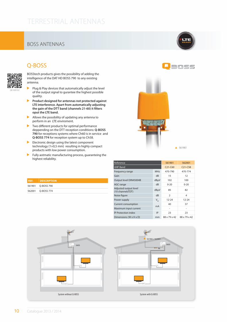
Reference 561901 562001
UHF Band C21-C60 C21-C58
Frequency range MHz 470-790 470-774
Gain dB 15 12
Output level DIN45004B dBµV 102 100
AGC range dB 0-20 0-20
Adjusted output level (10 channelsTDT)
dBµV 85 82
Noise #gure dB 2 4
Power supply Vdc
12-24 12-24
Current consumptionmA
40 37
Maximum input current - -
ÍP Protection index IP 23 23
Dimensions (W x H x D) mm 88 x 79 x 42 88 x 79 x 42
Q-BOSSBOSStech products gives the possibility of adding the intelligence of the DAT HD BOSS 790 to any existing antenna.
Plug & Play devices that automatically adjust the level of the output signal to gurantee the highest possible quality.
Product designed for antennas not protected against LTE interference. Apart from automatically adjusting the gain of the DTT band (channels 21-60) it "lters oput the LTE band.
Allows the possibility of updating any antenna to perform in an LTE enviroment.
Two di%erent products for optimal performance deppending on the DTT reception conditions: Q-BOSS 790 for receptions systems where Ch60 is in service and Q-BOSS 774 for reception system up to Ch58.
Electronic design using the latest component technology (1×0,5 mm) resulting in highly compact products with low power consumption.
Fully aotmatic manufacturing process, guaranteing the highest reliability.
REF. DESCRIPTION
561901 Q-BOSS 790
562001 Q-BOSS 774
561901
QR-A00162
TERRESTRIAL ANTENNAS
11 Catalogue 2013 / 2014
144111
BOSS ANTENNAS: SPECIALS
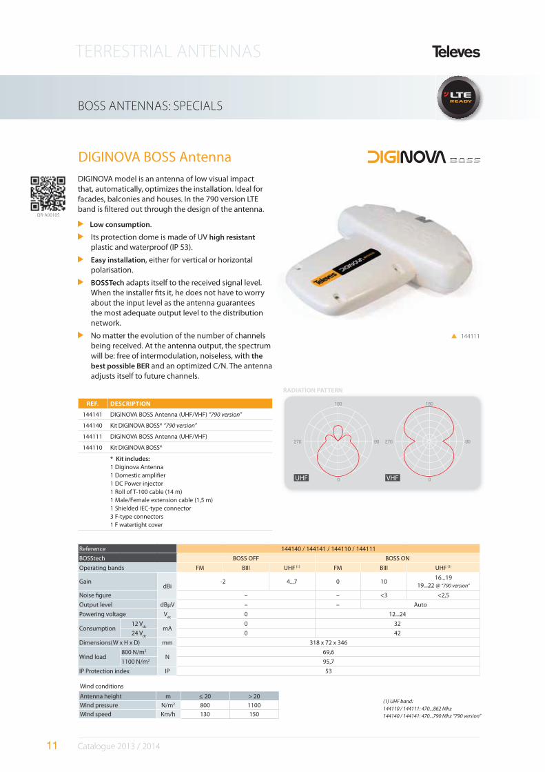
DIGINOVA BOSS Antenna
DIGINOVA model is an antenna of low visual impact that, automatically, optimizes the installation. Ideal for facades, balconies and houses. In the 790 version LTE band is #ltered out through the design of the antenna.
Low consumption.
Its protection dome is made of UV high resistant plastic and waterproof (IP 53).
Easy installation, either for vertical or horizontal polarisation.
BOSSTech adapts itself to the received signal level. When the installer #ts it, he does not have to worry about the input level as the antenna guarantees the most adequate output level to the distribution network.
No matter the evolution of the number of channels being received. At the antenna output, the spectrum will be: free of intermodulation, noiseless, with the
best possible BER and an optimized C/N. The antenna adjusts itself to future channels.
REF. DESCRIPTION
144141 DIGINOVA BOSS Antenna (UHF/VHF) “790 version”
144140 Kit DIGINOVA BOSS* “790 version”
144111 DIGINOVA BOSS Antenna (UHF/VHF)
144110 Kit DIGINOVA BOSS*
* Kit includes:
1 Diginova Antenna1 Domestic amplifier1 DC Power injector1 Roll of T-100 cable (14 m)1 Male/Female extension cable (1,5 m)1 Shielded IEC-type connector3 F-type connectors1 F watertight cover
Reference 144140 / 144141 / 144110 / 144111
BOSStech BOSS OFF BOSS ON
Operating bands FM BIII UHF (1) FM BIII UHF (1)
GaindBi
-2 4...7 0 1016...19
19...22 @ “790 version”
Noise #gure – – <3 <2,5
Output level dBµV – – Auto
Powering voltage Vdc
0 12...24
Consumption12 V
dc mA0 32
24 Vdc
0 42
Dimensions(W x H x D) mm 318 x 72 x 346
Wind load800 N/m2
N69,6
1100 N/m2 95,7
IP Protection index IP 53
Wind conditions
Antenna height m ≤ 20 > 20
Wind pressure N/m2 800 1100
Wind speed Km/h 130 150
VHFUHF
RADIATION PATTERN
QR-A00105
(1) UHF band:
144110 / 144111: 470...862 Mhz
144140 / 144141: 470...790 Mhz “790 version”
TERRESTRIAL ANTENNAS
12 Catalogue 2013 / 2014
BOSS ANTENNAS: SPECIALS
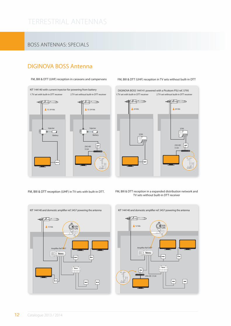
DIGINOVA BOSS Antenna
12-24 Vdc 12-24 Vdc 24 Vdc 24 Vdc
12 Vdc VdcON
12 Vdc VdcON
FM, BIII & DTT (UHF) reception in caravans and campervans
KIT 144140 with current inyector for powering from battery
KIT 144140 and domestic ampli#er ref. 5457 powering the antenna KIT 144140 and domestic ampli#er ref. 5457 powering the antenna
DIGINOVA BOSS 144141 powered with a Picokom PSU ref. 5795
1.TV set with built-in DTT receiver 1.TV set with built-in DTT receiver 2.TV set without built-in DTT receiver 2.TV set without built-in DTT receiver
FM, BIII & DTT reception (UHF) in TV sets with built-in DTT.
FM, BIII & DTT (UHF) reception in TV sets without built-in DTT
FM, BIII & DTT reception in a expanded distribution network andTV sets without built-in DTT receiver
Battery
Injector
Ampli#er Ref 5457 Ampli#er Ref 5457
Injector
ZAS HD
5124
ZAS HD
5124
ZAS HD 5124
5795
5795
Battery
TERRESTRIAL ANTENNAS
13 Catalogue 2013 / 2014
BOSS ANTENNAS: SPECIALS
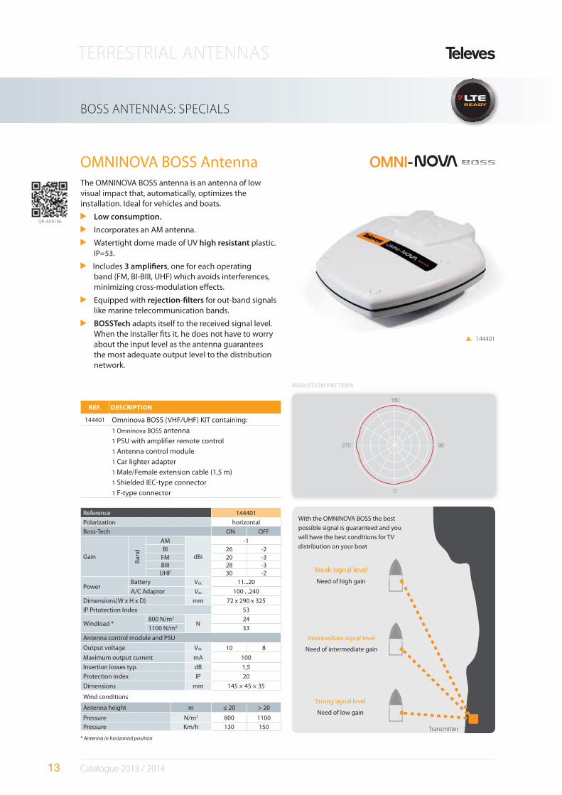
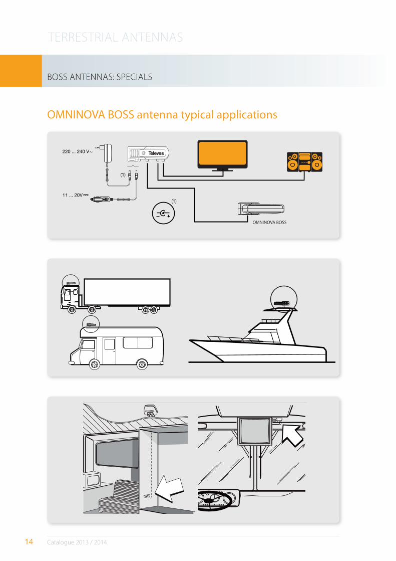
OMNINOVA BOSS Antenna
Reference 144401
Polarization horizontal
Boss-Tech ON OFF
Gain
Ban
d
AM
dBi
-1BI 26 -2
FM 20 -3BIII 28 -3
UHF 30 -2
PowerBattery Vdc 11...20
A/C Adaptor Vac 100 ...240
Dimensions(W x H x D) mm 72 x 290 x 325
IP Prtotection Index 53
Windload *800 N/m2
N24
1100 N/m2 33
Antenna control module and PSU
Output voltage Vdc 10 8
Maximum output current mA 100
Insertion losses typ. dB 1,5
Protection index IP 20
Dimensions mm 145 × 45 × 35
Wind conditions
Antenna height m ≤ 20 > 20
Pressure N/m2 800 1100
Pressure Km/h 130 150
REF. DESCRIPTION
144401 Omninova BOSS (VHF/UHF) KIT containing:
1 Omninova BOSS antenna
1 PSU with amplifier remote control
1 Antenna control module
1 Car lighter adapter
1 Male/Female extension cable (1,5 m)
1 Shielded IEC-type connector
1 F-type connector
144401
Weak signal level
Need of high gain
With the OMNINOVA BOSS the best
possible signal is guaranteed and you
will have the best conditions for TV
distribution on your boat
Intermediate signal level
Need of intermediate gain
Strong signal level
Need of low gain
Transmitter
* Antenna in horizontal position
RADIATION PATTERN
The OMNINOVA BOSS antenna is an antenna of low visual impact that, automatically, optimizes the installation. Ideal for vehicles and boats.
Low consumption.
Incorporates an AM antenna.
Watertight dome made of UV high resistant plastic. IP=53.
Includes 3 ampli"ers, one for each operating band (FM, BI-BIII, UHF) which avoids interferences, minimizing cross-modulation e%ects.
Equipped with rejection-"lters for out-band signals like marine telecommunication bands.
BOSSTech adapts itself to the received signal level. When the installer #ts it, he does not have to worry about the input level as the antenna guarantees the most adequate output level to the distribution network.
QR-A00106
TERRESTRIAL ANTENNAS
14 Catalogue 2013 / 2014
OMNINOVA BOSS antenna typical applications
BOSS ANTENNAS: SPECIALS
OMNINOVA BOSS
TERRESTRIAL ANTENNAS
15 Catalogue 2013 / 2014
BOSS ANTENNAS: INDOOR
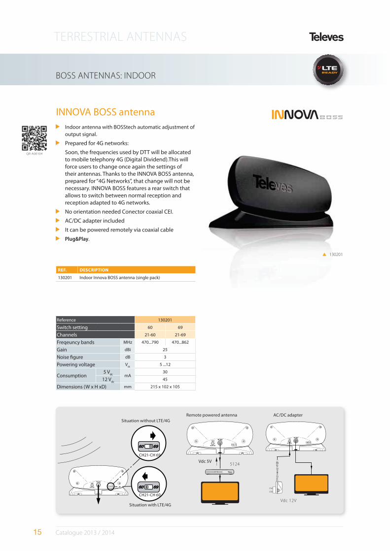
INNOVA BOSS antennaIndoor antenna with BOSStech automatic adjustment of output signal.
Prepared for 4G networks:
Soon, the frequencies used by DTT will be allocated to mobile telephony 4G (Digital Dividend).This will force users to change once again the settings of their antennas. Thanks to the INNOVA BOSS antenna, prepared for “4G Networks”, that change will not be necessary. INNOVA BOSS features a rear switch that allows to switch between normal reception and reception adapted to 4G networks.
No orientation needed Conector coaxial CEI.
AC/DC adapter included
It can be powered remotely via coaxial cable
Plug&Play.
130201
Reference 130201
Switch setting 60 69
Channels 21-60 21-69
Freqeuncy bands MHz 470...790 470...862
Gain dBi 25
Noise #gure dB 3
Powering voltage Vdc
5 ...12
Consumption5 V
dc mA30
12 Vdc
45
Dimensions (W x H xD) mm 215 x 102 x 105
REF. DESCRIPTION
130201 Indoor Innova BOSS antenna (single pack)
Vdc 5V
Remote powered antenna AC/DC adapter
Vdc 12V
5124
Situation without LTE/4G
Situation with LTE/4G
CH21-CH 69
CH21-CH 60
QR-A00104
TERRESTRIAL ANTENNAS
16 Catalogue 2013 / 2014
INDOOR ANTENNAS
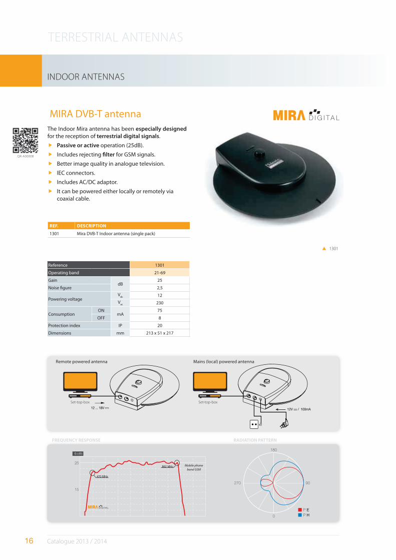
MIRA DVB-T antennaThe Indoor Mira antenna has been especially designed for the reception of terrestrial digital signals.
Passive or active operation (25dB).
Includes rejecting "lter for GSM signals.
Better image quality in analogue television.
IEC connectors.
Includes AC/DC adaptor.
It can be powered either locally or remotely via coaxial cable.
Reference 1301
Operating band 21-69
GaindB
25
Noise #gure 2,5
Powering voltageV
dc 12
Vac 230
ConsumptionON
mA75
OFF 8
Protection index IP 20
Dimensions mm 213 x 51 x 217
1301
G (dBi)
12V / 100mA12 ... 18V
Set-top-box Set-top-box
FREQUENCY RESPONSE RADIATION PATTERN
REF. DESCRIPTION
1301 Mira DVB-T Indoor antenna (single pack)
Remote powered antenna Mains (local) powered antenna
QR-A00008
Mobile phone
band GSM
TERRESTRIAL ANTENNAS
17 Catalogue 2013 / 2014
ACCESSORIES FOR BOSS ANTENNAS
PicoKom Series Power Supply Units, “ F“
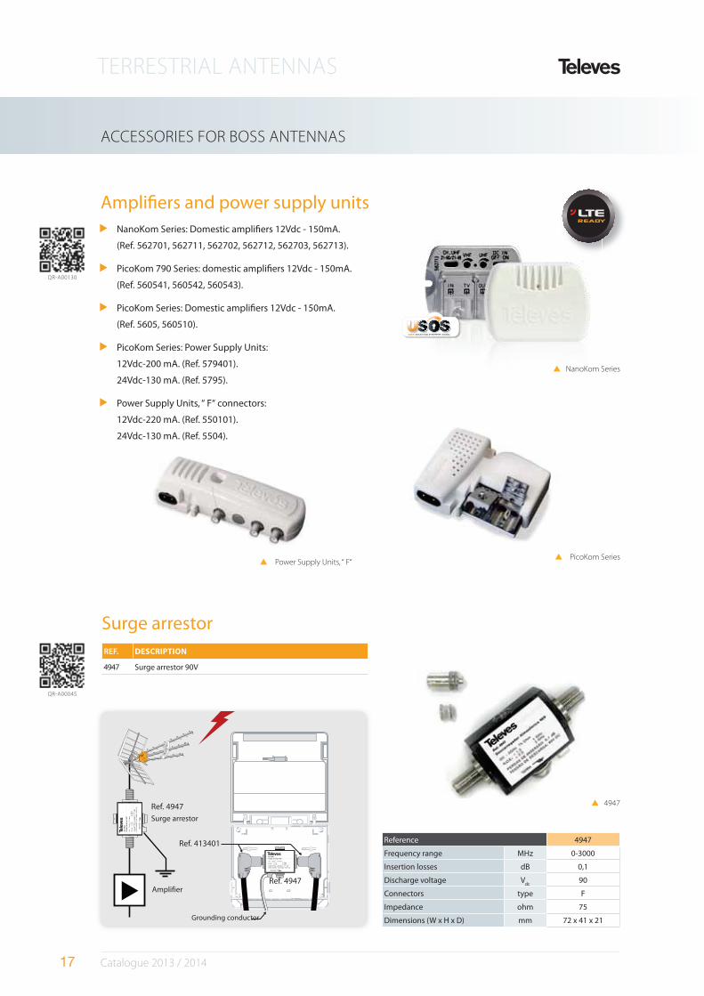
Ampli#ers and power supply units
Ref. 4947
Surge arrestor
Amplifier
4947
Grounding conductor
Ref. 4947
Ref. 413401 Reference 4947
Frequency range MHz 0-3000
Insertion losses dB 0,1
Discharge voltage Vdc
90
Connectors type F
Impedance ohm 75
Dimensions (W x H x D) mm 72 x 41 x 21
Surge arrestor
REF. DESCRIPTION
4947 Surge arrestor 90V
NanoKom Series
QR-A00130
QR-A00045
NanoKom Series: Domestic ampli#ers 12Vdc - 150mA.
(Ref. 562701, 562711, 562702, 562712, 562703, 562713).
PicoKom 790 Series: domestic ampli#ers 12Vdc - 150mA.
(Ref. 560541, 560542, 560543).
PicoKom Series: Domestic ampli#ers 12Vdc - 150mA.
(Ref. 5605, 560510).
PicoKom Series: Power Supply Units:
12Vdc-200 mA. (Ref. 579401).
24Vdc-130 mA. (Ref. 5795).
Power Supply Units, “ F“ connectors:
12Vdc-220 mA. (Ref. 550101).
24Vdc-130 mA. (Ref. 5504).
TERRESTRIAL ANTENNAS
18 Catalogue 2013 / 2014
FM & VHF ANTENNAS
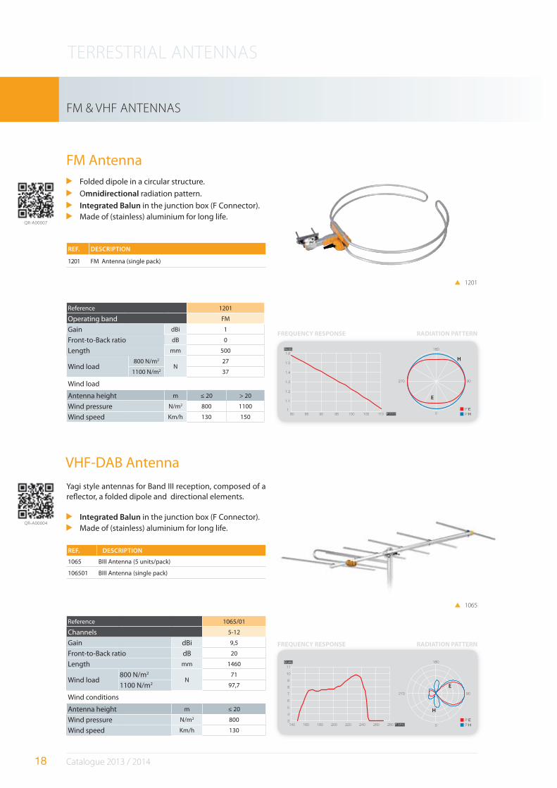
FM Antenna
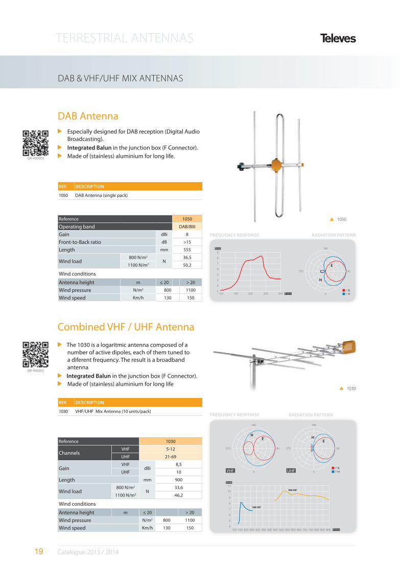
VHF-DAB Antenna
Folded dipole in a circular structure.
Omnidirectional radiation pattern.
Integrated Balun in the junction box (F Connector).
Made of (stainless) aluminium for long life.
Yagi style antennas for Band III reception, composed of a re$ector, a folded dipole and directional elements.
Integrated Balun in the junction box (F Connector).
Made of (stainless) aluminium for long life.
Reference 1065/01
Channels 5-12
Gain dBi 9,5
Front-to-Back ratio dB 20
Length mm 1460
Wind load800 N/m2
N71
1100 N/m2 97,7
Wind conditions
Antenna height m ≤ 20
Wind pressure N/m2 800
Wind speed Km/h 130
REF. DESCRIPTION
1065 BIII Antenna (5 units/pack)
106501 BIII Antenna (single pack)
1201
1065
Reference 1201
Operating band FM
Gain dBi 1
Front-to-Back ratio dB 0
Length mm 500
Wind load800 N/m2
N27
1100 N/m2 37
Wind load
Antenna height m ≤ 20 > 20
Wind pressure N/m2 800 1100
Wind speed Km/h 130 150
REF. DESCRIPTION
1201 FM Antenna (single pack)
(dBi)
FREQUENCY RESPONSE RADIATION PATTERN
E
H
(dBi)
FREQUENCY RESPONSE RADIATION PATTERN
E
H
QR-A00007
QR-A00004
TERRESTRIAL ANTENNAS
19 Catalogue 2013 / 2014
DAB & VHF/UHF MIX ANTENNAS
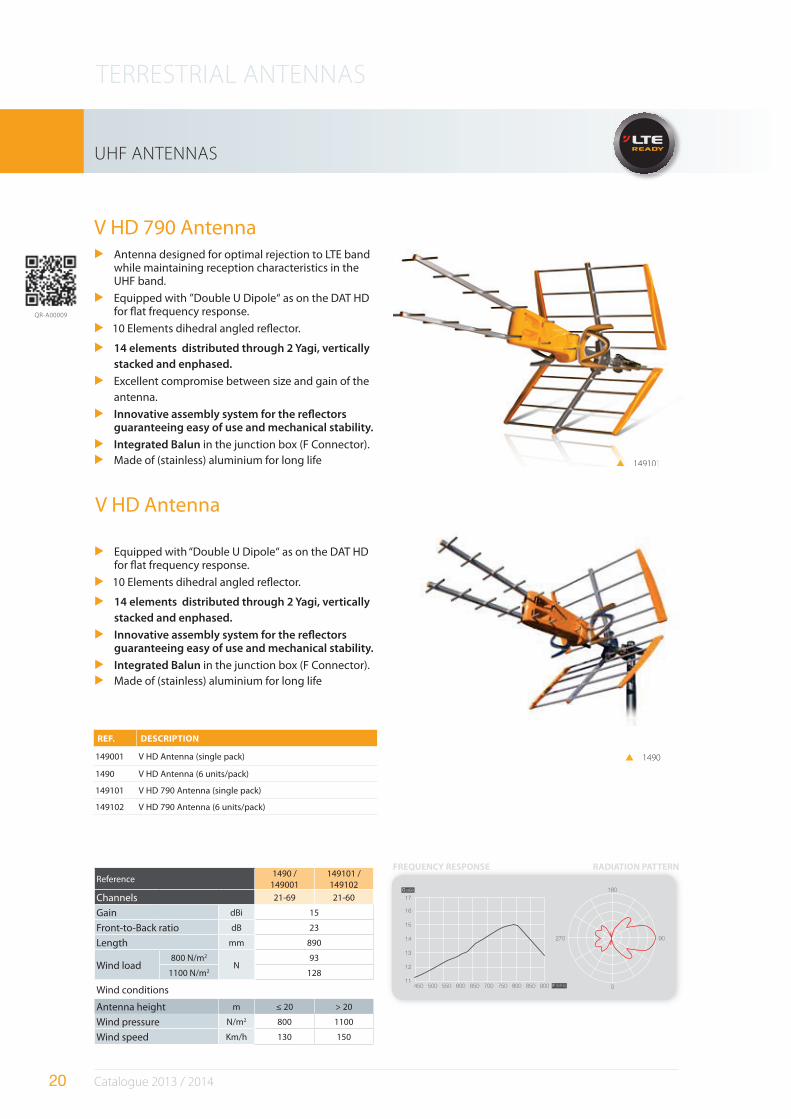
DAB Antenna
Combined VHF / UHF Antenna
Especially designed for DAB reception (Digital Audio Broadcasting).
Integrated Balun in the junction box (F Connector).
Made of (stainless) aluminium for long life.
The 1030 is a logaritmic antenna composed of a number of active dipoles, each of them tuned to a diferent frequency. The result is a broadband antenna
Integrated Balun in the junction box (F Connector).
Made of (stainless) aluminium for long life
Reference 1050
Operating band DAB/BIII
Gain dBi 8
Front-to-Back ratio dB >15
Length mm 555
Wind load800 N/m2
N36,5
1100 N/m2 50,2
Wind conditions
Antenna height m ≤ 20 > 20
Wind pressure N/m2 800 1100
Wind speed Km/h 130 150
Reference 1030
ChannelsVHF 5-12
UHF 21-69
GainVHF
dBi8,5
UHF 10
Length mm 900
Wind load800 N/m2
N33,6
1100 N/m2 46,2
Wind conditions
Antenna height m ≤ 20 > 20
Wind pressure N/m2 800 1100
Wind speed Km/h 130 150
1030
1050
REF. DESCRIPTION
1050 DAB Antenna (single pack)
REF. DESCRIPTION
1030 VHF/UHF Mix Antenna (10 units/pack)
(dBi)
FREQUENCY RESPONSE RADIATION PATTERN
E
H
UHFVHF
(dBi)
FREQUENCY RESPONSE RADIATION PATTERN
EE
HH
QR-A00003
QR-A00002
TERRESTRIAL ANTENNAS
20 Catalogue 2013 / 2014
UHF ANTENNAS
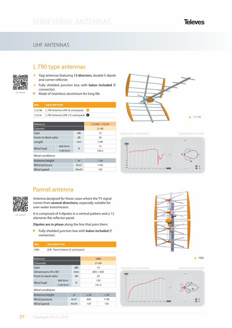
Antenna designed for optimal rejection to LTE band while maintaining reception characteristics in the UHF band.
Equipped with ”Double U Dipole“ as on the DAT HD for $at frequency response.
10 Elements dihedral angled re$ector.
14 elements distributed through 2 Yagi, vertically
stacked and enphased.
Excellent compromise between size and gain of the
antenna.
Innovative assembly system for the re#ectors guaranteeing easy of use and mechanical stability.
Integrated Balun in the junction box (F Connector).
Made of (stainless) aluminium for long life
REF. DESCRIPTION
149001 V HD Antenna (single pack)
1490 V HD Antenna (6 units/pack)
149101 V HD 790 Antenna (single pack)
149102 V HD 790 Antenna (6 units/pack)
Reference1490 /
149001149101 / 149102
Channels 21-69 21-60
Gain dBi 15
Front-to-Back ratio dB 23
Length mm 890
Wind load800 N/m2
N93
1100 N/m2 128
Wind conditions
Antenna height m ≤ 20 > 20
Wind pressure N/m2 800 1100
Wind speed Km/h 130 150
V HD 790 Antenna
1490
149101
(dBi)
RADIATION PATTERNFREQUENCY RESPONSE
QR-A00009
Equipped with “Double U Dipole“ as on the DAT HD for $at frequency response.
10 Elements dihedral angled re$ector.
14 elements distributed through 2 Yagi, vertically
stacked and enphased.
Innovative assembly system for the re#ectors guaranteeing easy of use and mechanical stability.
Integrated Balun in the junction box (F Connector).
Made of (stainless) aluminium for long life
V HD Antenna
149101
TERRESTRIAL ANTENNAS
21 Catalogue 2013 / 2014
UHF ANTENNAS
Antenna designed for those cases where the TV signal comes from several directions, especially suitable for over-water transmission.
It is composed of 4 dipoles in a vertical pattern and a 12 elements $at re$ector panel.
Dipoles are in phase along the line that joins them.
Fully shielded junction box with balun included (F connector).
Pannel antenna
Reference 1083
Channels 21-69
Gain dBi 14
Dimensions (H x W) mm 805 × 560
Front to back ratio dB 20
Wind load800 N/m2
N139
1100 N/m2 191,5
Wind conditions
Antenna height m ≤ 20 > 20
Wind pressure N/m2 800 1100
Wind speed Km/h 130 150
REF. DESCRIPTION
1083 UHF Panel Antena (5 units/pack)
1083
L 790 type antennasYagi antennas featuring 13 directors, double V dipole and corner re$ector.
Fully shielded junction box with balun included (F connector).Made of (stainless) aluminium for long life.
REF. DESCRIPTION
112140 L 790 Antenna UHF (6 units/pack) Or
112141 L 790 Antenna UHF (15 units/pack) B
Reference 112140 / 112141
Channels 21-60
Gain dBi 12
Front-to-Back ratio dB 26
Length mm 1180
Wind load800 N/m2
N73
1100 N/m2 100,3
Wind conditions
Antenna height m > 20
Wind pressure N/m2 1100
Wind speed Km/h 150
FREQUENCY RESPONSE RADIATION PATTERN
(dBi)
FREQUENCY RESPONSE RADIATION PATTERN
E
H
QR-A00006
QR-A00005
112140
(dBi)
-25
-20
-15
-10
-5
0
5
10
15
20
E
H
TERRESTRIAL ANTENNAS
22 Catalogue 2013 / 2014
TELECOMMUNICATION ANTENNAS
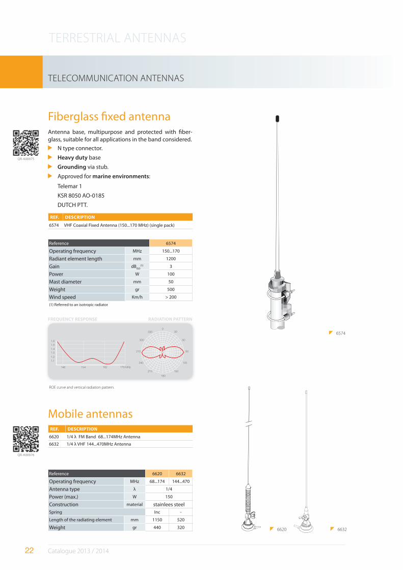
Antenna base, multipurpose and protected with #ber-glass, suitable for all applications in the band considered.
N type connector.
Heavy duty base
Grounding via stub.
Approved for marine environments:
Telemar 1
KSR 8050 AO-0185
DUTCH PTT.
Reference 6574
Operating frequency MHz 150...170
Radiant element length mm 1200
Gain dBISO
(1) 3
Power W 100
Mast diameter mm 50
Weight gr 500
Wind speed Km/h > 200
(1) Referred to an isotropic radiator
Reference 6620 6632
Operating frequency MHz 68...174 144...470
Antenna type λ 1/4
Power (max.) W 150
Construction material stainlees steel
Spring Inc -
Length of the radiating element mm 1150 520
Weight gr 440 320
Fiberglass #xed antenna
Mobile antennasREF. DESCRIPTION
6620 1/4 λ FM Band 68...174MHz Antenna
6632 1/4 λ VHF 144...470MHz Antenna
REF. DESCRIPTION
6574 VHF Coaxial Fixed Antenna (150...170 MHz) (single pack)
6620 6632
1.6
1.5
1.4
1.3
1.2
1.1
146 154 162 170 MHz
0330
300
270
240
210
180
150
120
90
60
30 6574
ROE curve and vertical radiation pattern.
FREQUENCY RESPONSE RADIATION PATTERN
QR-A00075
QR-A00076

TERRESTRIAL ANTENNAS
23 Catalogue 2013 / 2014
SATÉLITE
23 Satélite
MECHANICAL ACCESSORIES
A range of elements intended to support TV reception devices like antennas or dishes, no matter where they are going to be placed: eaves, gable ends, walls, roof, windows, ...etc.
There are many models ready to be mounted by means of either mortar courses or expansion/through/chemical bolts.
All of them feature a surface treated with a dual process, galvanised and reactive sealed, to ensure a long life against rusting.
TERRESTRIAL ANTENNAS
24 Catalogue 2013 / 2014
MASTS, SUPPLEMENTS & BRACKETS
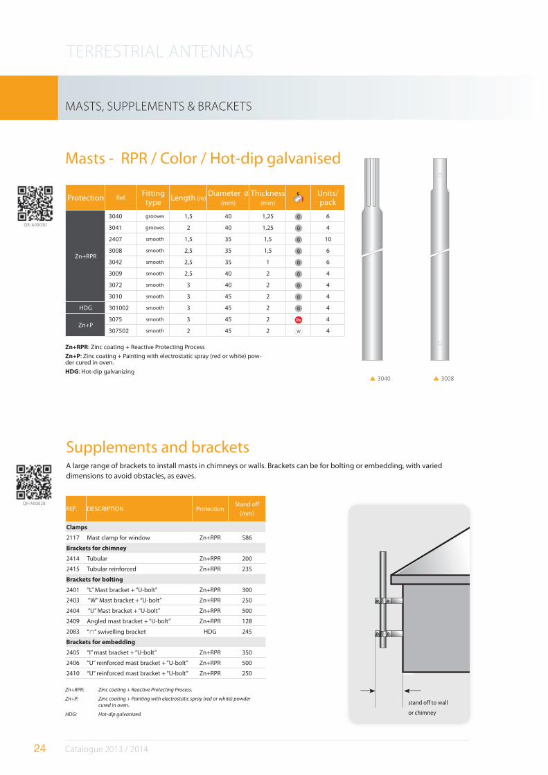
Masts - RPR / Color / Hot-dip galvanised
Supplements and brackets
REF. DESCRIPTION ProtectionStand off
(mm)
Clamps
2117 Mast clamp for window Zn+RPR 586
Brackets for chimney
2414 Tubular Zn+RPR 200
2415 Tubular reinforced Zn+RPR 235
Brackets for bolting
2401 “L” Mast bracket + “U-bolt” Zn+RPR 300
2403 “W” Mast bracket + “U-bolt” Zn+RPR 250
2404 “U” Mast bracket + “U-bolt” Zn+RPR 500
2409 Angled mast bracket + “U-bolt” Zn+RPR 128
2083 “ ” swivelling bracket HDG 245
Brackets for embedding
2405 “I” mast bracket + “U-bolt” Zn+RPR 350
2406 “U” reinforced mast bracket + “U-bolt” Zn+RPR 500
2410 “U” reinforced mast bracket + “U-bolt” Zn+RPR 250
Protection Ref.Fitting
typeLength (m)
Diameter Ø
(mm)
Thickness (mm)
Units/ pack
Zn+RPR
3040 grooves 1,5 40 1,25 G 6
3041 grooves 2 40 1,25 G 4
2407 smooth 1,5 35 1,5 G 10
3008 smooth 2,5 35 1,5 G 6
3042 smooth 2,5 35 1 G 6
3009 smooth 2,5 40 2 G 4
3072 smooth 3 40 2 G 4
3010 smooth 3 45 2 G 4
HDG 301002 smooth 3 45 2 G 4
Zn+P3075 smooth 3 45 2 Re 4
307502 smooth 2 45 2 W 4
3008 3040
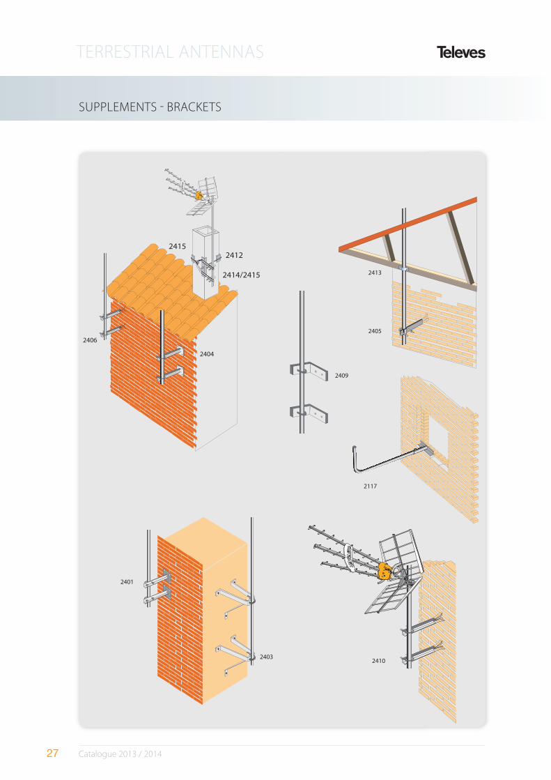
A large range of brackets to install masts in chimneys or walls. Brackets can be for bolting or embedding, with varied dimensions to avoid obstacles, as eaves.
stand o" to wall
or chimney
Zn+RPR: Zinc coating + Reactive Protecting Process.
Zn+P: Zinc coating + Painting with electrostatic spray (red or white) powder
cured in oven.
HDG: Hot-dip galvanized.
Zn+RPR: Zinc coating + Reactive Protecting Process
Zn+P: Zinc coating + Painting with electrostatic spray (red or white) pow-der cured in oven.
HDG: Hot-dip galvanizing
QR-A00030
QR-A00028
TERRESTRIAL ANTENNAS
25 Catalogue 2013 / 2014
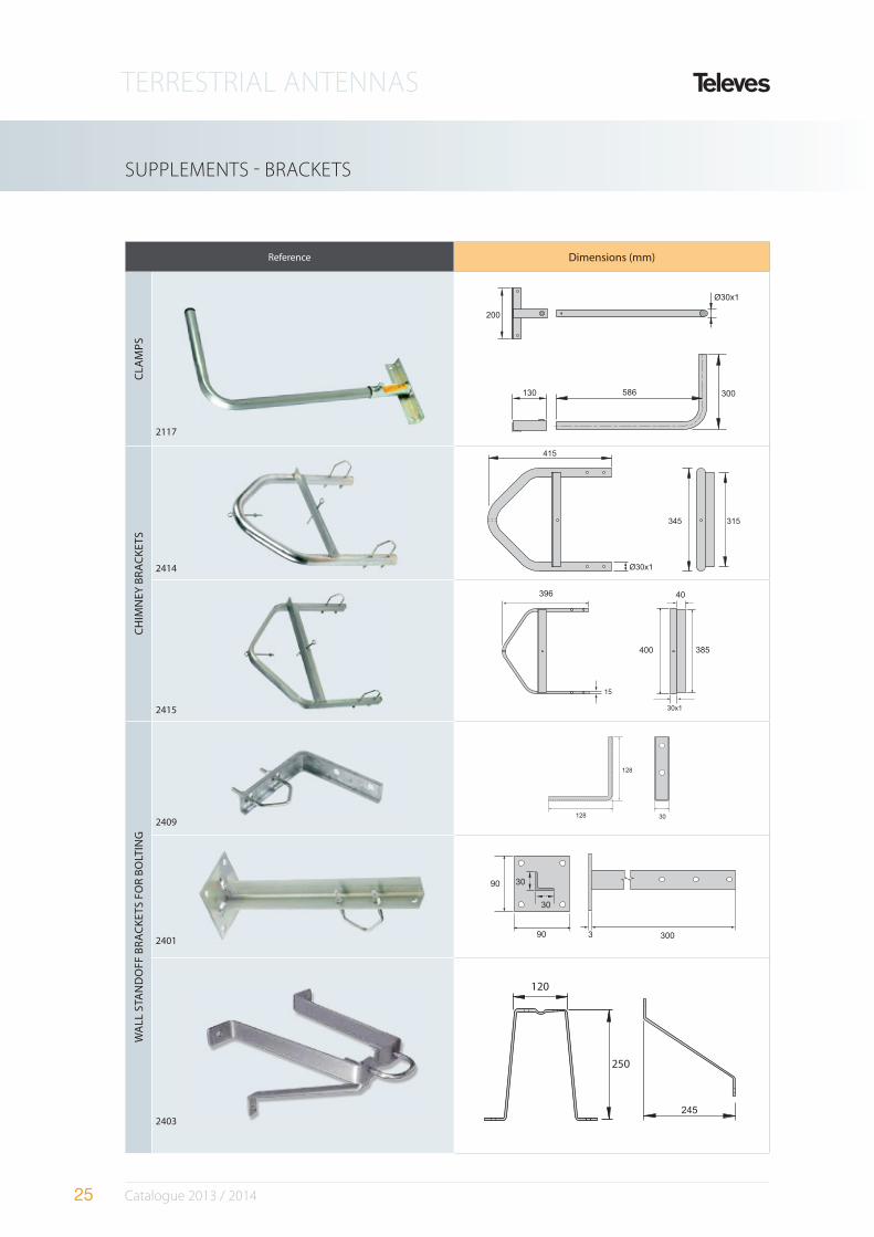
SUPPLEMENTS - BRACKETS
Reference Dimensions (mm)
CLA
MP
S
2117
CH
IMN
EY B
RA
CK
ETS
2414
2415
400 385
40396
15
30x1
WA
LL S
TAN
DO
FF B
RA
CK
ETS
FO
R B
OLT
ING
2409 128
128
30
2401 3 300
90
90
30
30
2403
250
120
TERRESTRIAL ANTENNAS
26 Catalogue 2013 / 2014
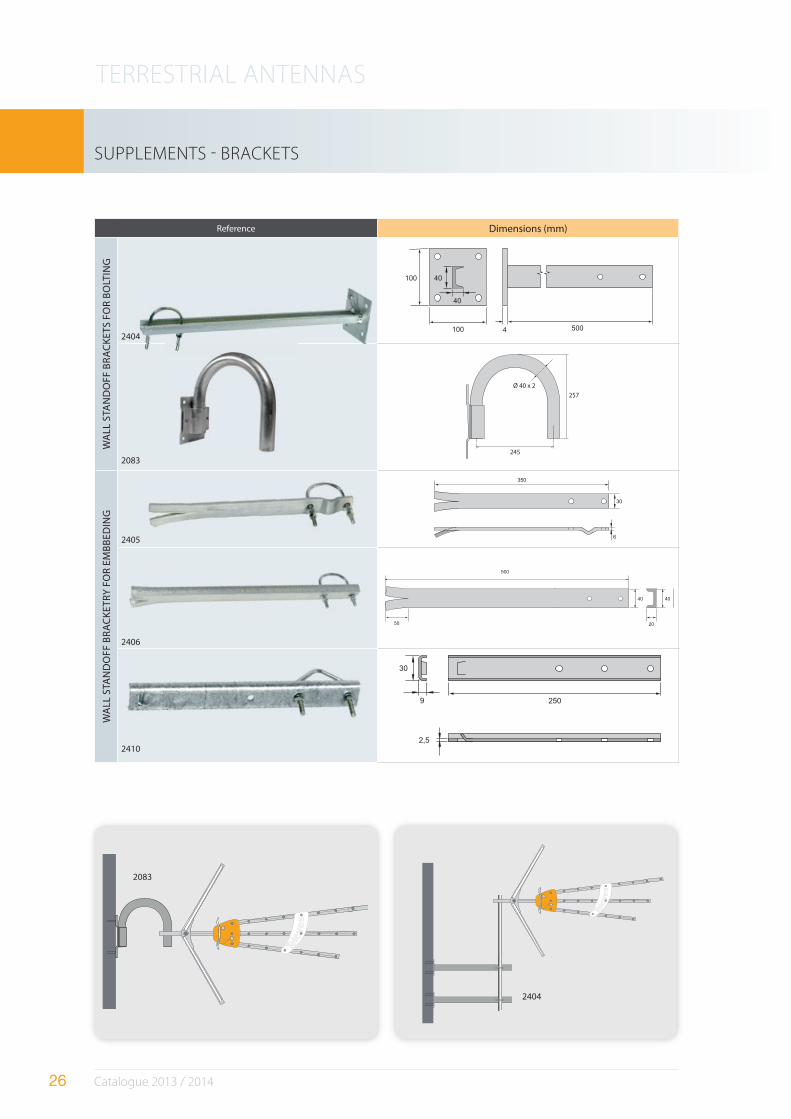
Reference Dimensions (mm)
WA
LL S
TAN
DO
FF B
RA
CK
ETS
FO
R B
OLT
ING
24044 500
100
100
30
3040
40
2083
Ø 40 x 2
257
245
WA
LL S
TAN
DO
FF B
RA
CK
ETR
Y F
OR
EM
BB
EDIN
G
2405
30
350
6
2406
500
50
40
20
40
2410
9
30
2,5
250
SUPPLEMENTS - BRACKETS
2083
2404
2404
TERRESTRIAL ANTENNAS
27 Catalogue 2013 / 2014
2413
2405
2409
2412
2415
2414/2415
2404
2406
2410
SUPPLEMENTS - BRACKETS
2117
2403
2401
TERRESTRIAL ANTENNAS
28 Catalogue 2013 / 2014
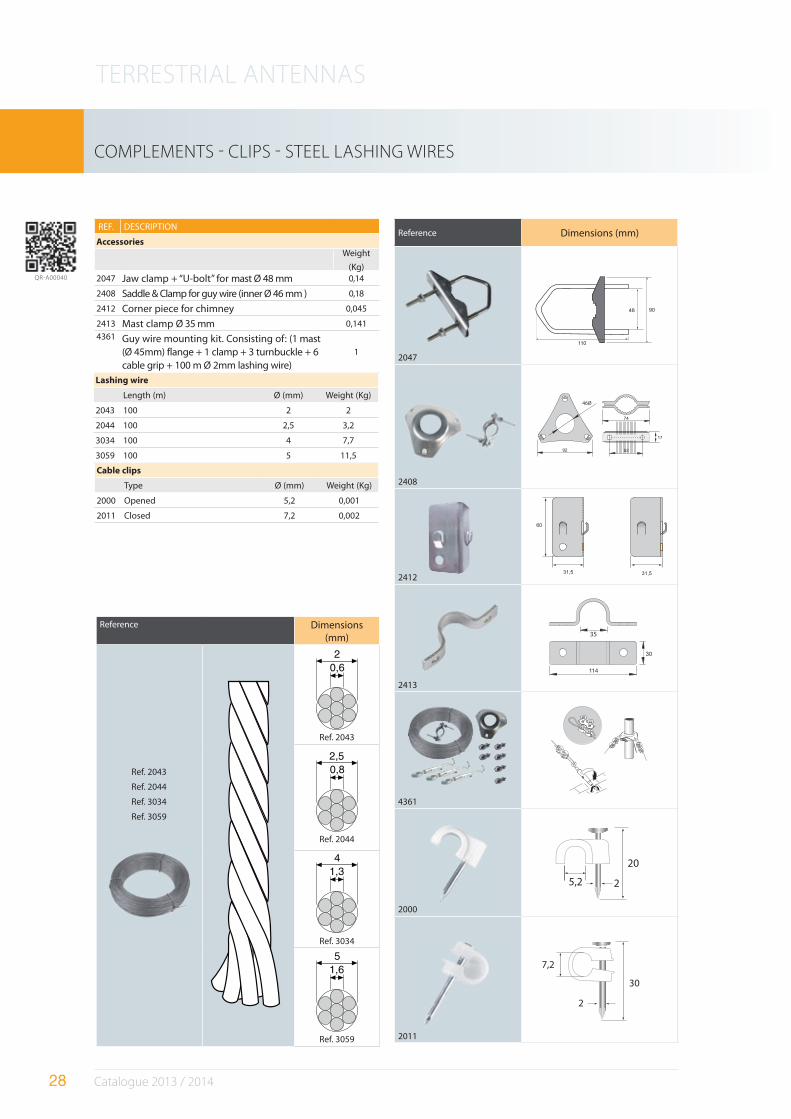
Reference Dimensions (mm)
2047
90 48
110
2408
46Ø
2412
60
31,5 31,5
2413
35
4361
2000
20
25,2
2011
30
2
7,2
Reference Dimensions (mm)
Ref. 2043
Ref. 2044
Ref. 3034
Ref. 3059
Ref. 2043
Ref. 2044
Ref. 3034
Ref. 3059
COMPLEMENTS - CLIPS - STEEL LASHING WIRES
REF. DESCRIPTION
Accessories
Weight
(Kg)2047 Jaw clamp + “U-bolt” for mast Ø 48 mm 0,14
2408 Saddle & Clamp for guy wire (inner Ø 46 mm ) 0,18
2412 Corner piece for chimney 0,045
2413 Mast clamp Ø 35 mm 0,141
4361 Guy wire mounting kit. Consisting of: (1 mast (Ø 45mm) flange + 1 clamp + 3 turnbuckle + 6 cable grip + 100 m Ø 2mm lashing wire)
1
Lashing wire
Length (m) Ø (mm) Weight (Kg)
2043 100 2 2
2044 100 2,5 3,2
3034 100 4 7,7
3059 100 5 11,5
Cable clips
Type Ø (mm) Weight (Kg)
2000 Opened 5,2 0,001
2011 Closed 7,2 0,002
QR-A00040