1 internetworking : internet architecture and tcp/ip protocol tk3133 computer networking technology
TRANSCRIPT
1
Internetworking : Internet architecture and TCP/IP Protocol
TK3133Computer
Networking Technology
2
Introduction
Internetworking :– Concept– Architecture– Protocol

3
Introduction
In the real world, computer is connected to various technology of LAN and WAN
In reality, network is heterogeneous – various network (and it is not homogeneous)
Contain millions of networks which connected to high-speed backbone
Each systems should adapt to various technology Introduce to internetworking concept

4
Internetworking
Internetworking is a schema for connecting various network with different technology
Use both hardware and software Additional hardware are placed between network Software is in the computer that is connected with Connected networking system is called internetwork /
internet Also called as virtual network
5
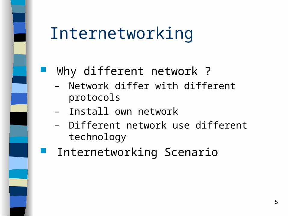
Internetworking
Why different network ?– Network differ with different protocols– Install own network – Different network use different technology
Internetworking Scenario
6
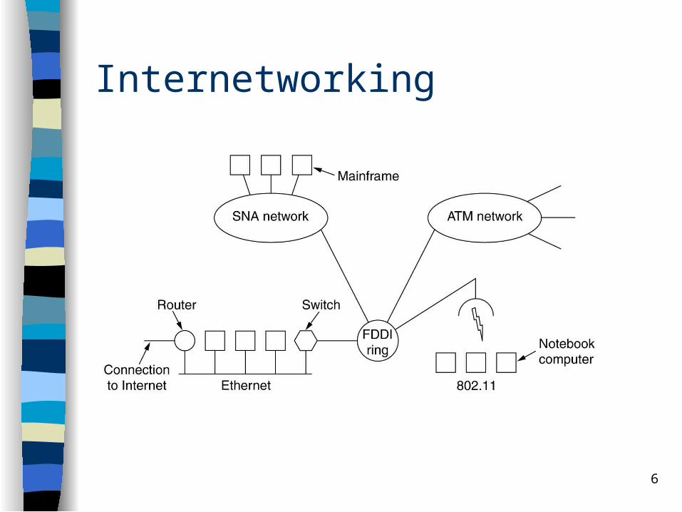
Internetworking
7
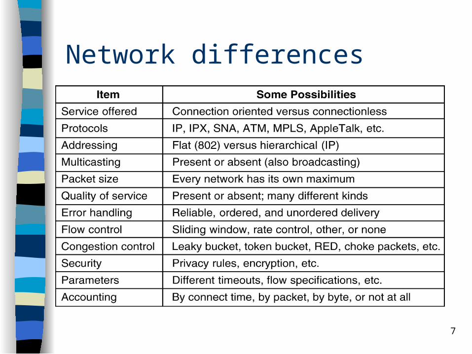
Network differences

8
Physical network connection using router Router is a component or hardware device which is
used to connect networking Router has more interface on various networking Router send and deliver packet between networks Change the packet if necessary to fulfill the
standard of each network with different technology (is also called as gateway)

9
Router
Example of two physical networks connected to a router that contain 2 different interfaces for each network connection
10
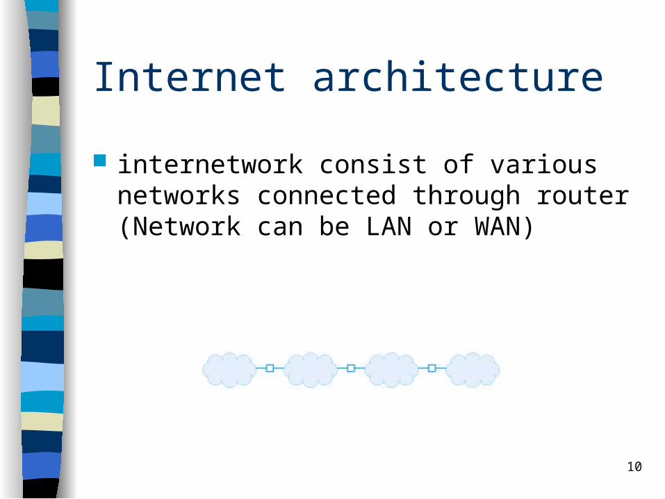
Internet architecture
internetwork consist of various networks connected through router (Network can be LAN or WAN)

11
Internet architecture
Router can have more that two interfaces
12
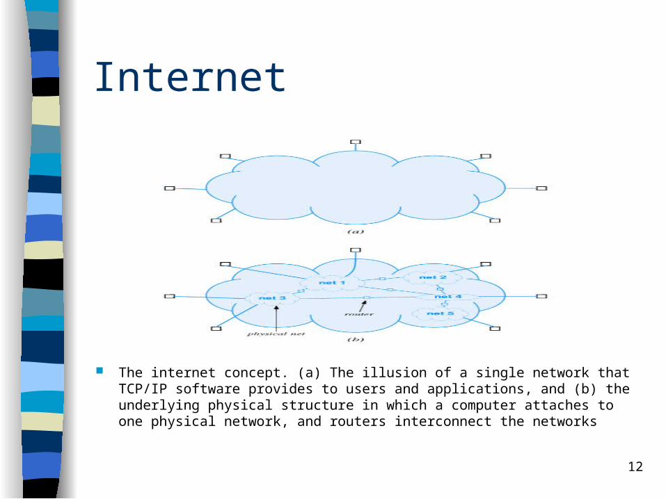
Internet
The internet concept. (a) The illusion of a single network that TCP/IP software provides to users and applications, and (b) the underlying physical structure in which a computer attaches to one physical network, and routers interconnect the networks
13
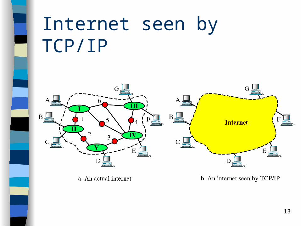
Internet seen by TCP/IP
14
Protocol for Internet
TCP/IP is the most popular internetworking protocol
The first internetworking protocol Maintain by ARPA and taken over by
NSF Independent to platform and
manufacturer
15
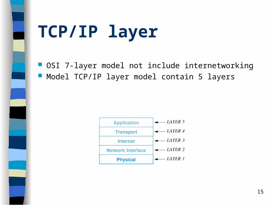
TCP/IP layer
OSI 7-layer model not include internetworking Model TCP/IP layer model contain 5 layers
16
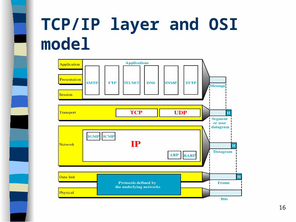
TCP/IP layer and OSI model
17
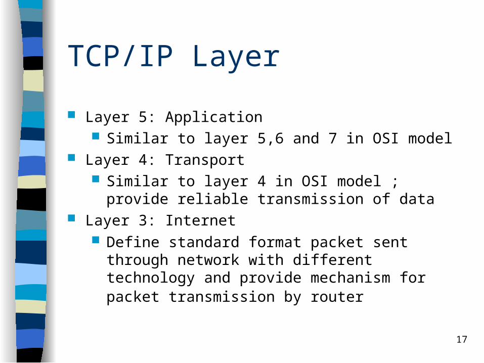
TCP/IP Layer
Layer 5: Application Similar to layer 5,6 and 7 in OSI model
Layer 4: Transport Similar to layer 4 in OSI model ; provide reliable
transmission of data Layer 3: Internet
Define standard format packet sent through network with different technology and provide mechanism for packet transmission by router
18
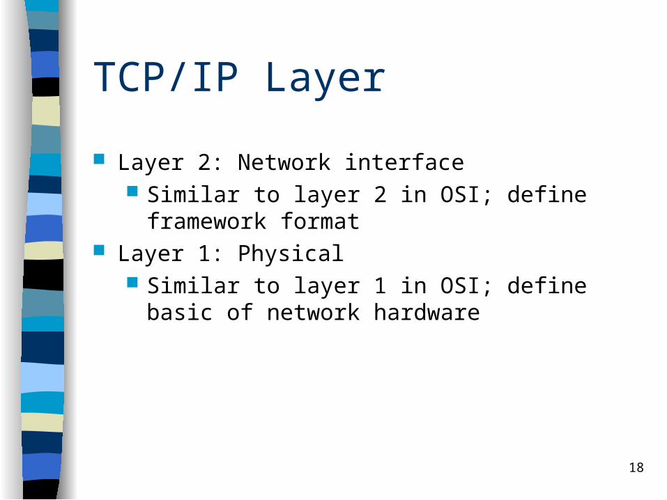
TCP/IP Layer
Layer 2: Network interface Similar to layer 2 in OSI; define framework format
Layer 1: Physical Similar to layer 1 in OSI; define basic of network
hardware
19
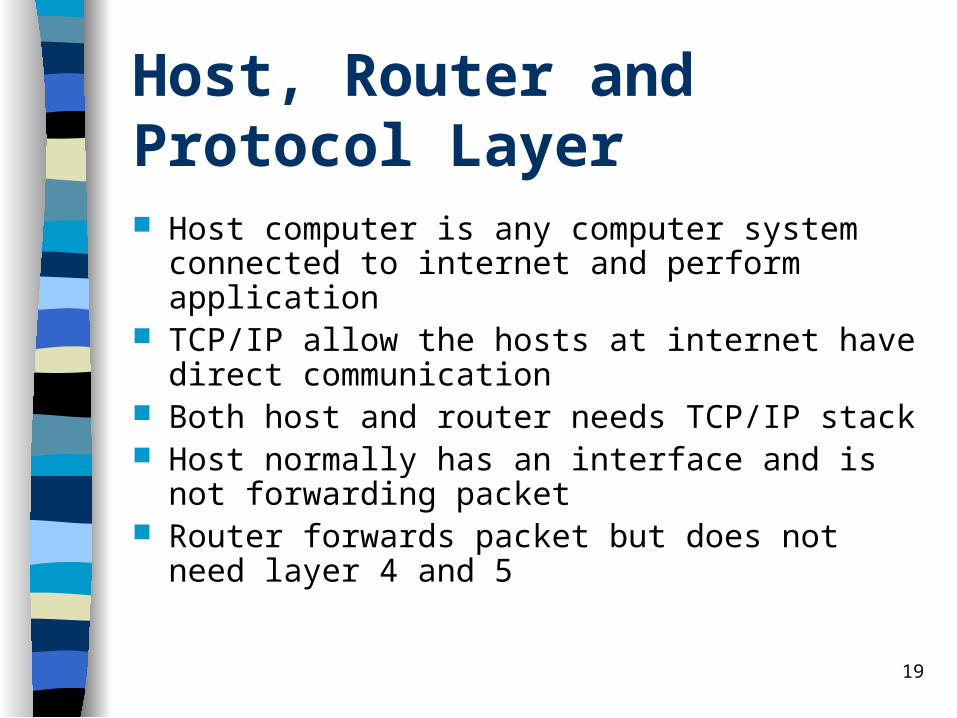
Host, Router and Protocol Layer Host computer is any computer system connected to
internet and perform application TCP/IP allow the hosts at internet have direct
communication Both host and router needs TCP/IP stack Host normally has an interface and is not forwarding
packet Router forwards packet but does not need layer 4
and 5
20
Network Layer Internet Protocol (IP)
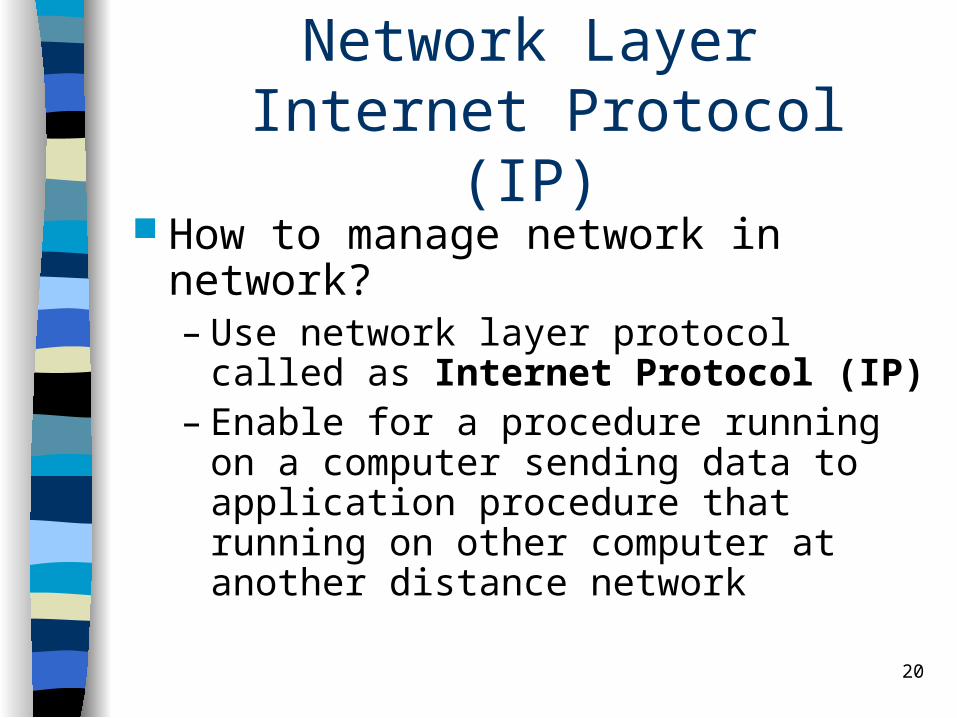
How to manage network in network?– Use network layer protocol called as
Internet Protocol (IP)– Enable for a procedure running on a
computer sending data to application procedure that running on other computer at another distance network

21
Internet Protocol (IP)
IP responsible for providing best-effort transmission for packet (or datagram)
How is the communication in the Internet ?– Transport layer takes data flow and divides them
into datagram– Network layer send each datagram through
Internet. Division into smaller unit may happen during this process.
22
Internet Protocol(IP)
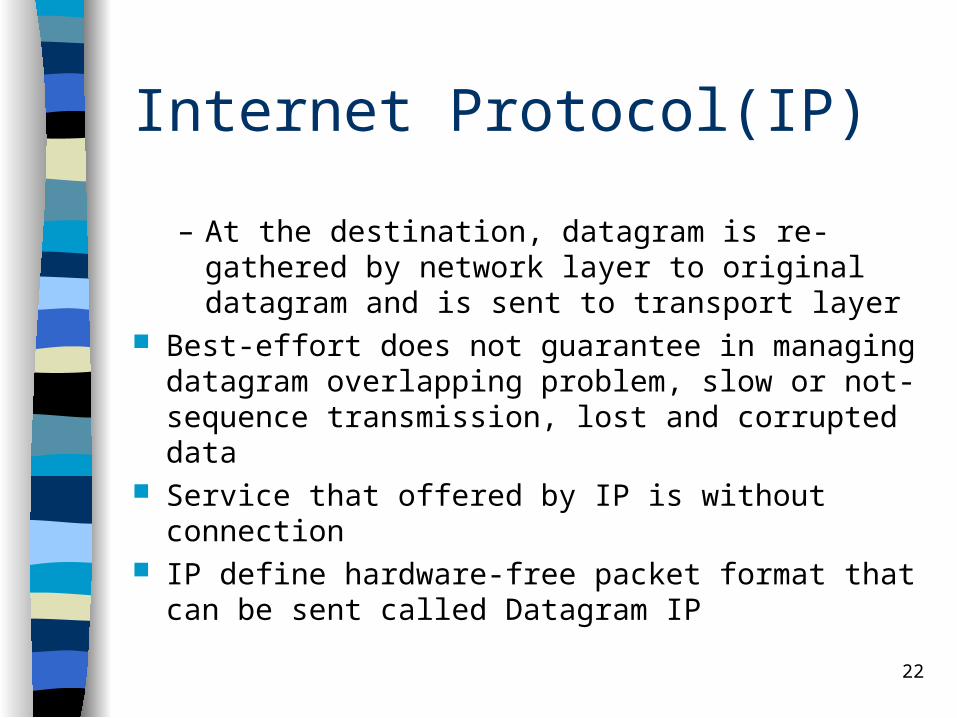
– At the destination, datagram is re-gathered by network layer to original datagram and is sent to transport layer
Best-effort does not guarantee in managing datagram overlapping problem, slow or not-sequence transmission, lost and corrupted data
Service that offered by IP is without connection IP define hardware-free packet format that can be
sent called Datagram IP

23
Datagram IP
IPv4 defines datagram at maximum 64Kb Head format datagram IP

24
Head Protocol of IPv4
25
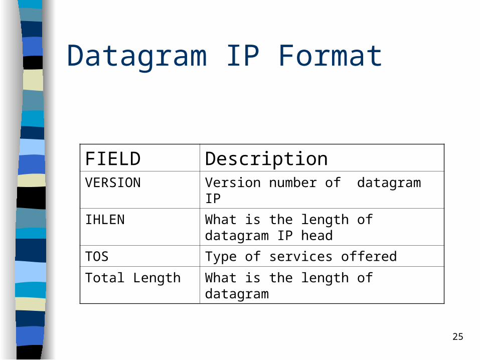
Datagram IP Format
FIELD Description VERSION Version number of datagram IP
IHLEN What is the length of datagram IP head
TOS Type of services offered
Total Length What is the length of datagram

26
IP Protocol
Field Description
Identification Unique identification to datagram
Fragment Offset Offset for fragment
Time To Live Counter to maximum number of datagram longevity
Protocol Give protocol to top layer
Checksum Define genuine of head
Source/destination address
Full address of source/destination node
Option May be contain security option

27
Fragmentation
Each network technology define the maximum data that can be sent in a packet. This limitation called MTU (Maximum Transmission Unit).
When a router accept a datagram that bigger than MTU, router would fragment datagram into smaller fragment
Each fragment is sent to a destination that responsible to match/reconnect the original datagram

28
Fragmentation
a) Transparent fragmentation
b) Nontransparent fragmentation
29
Fragmentation
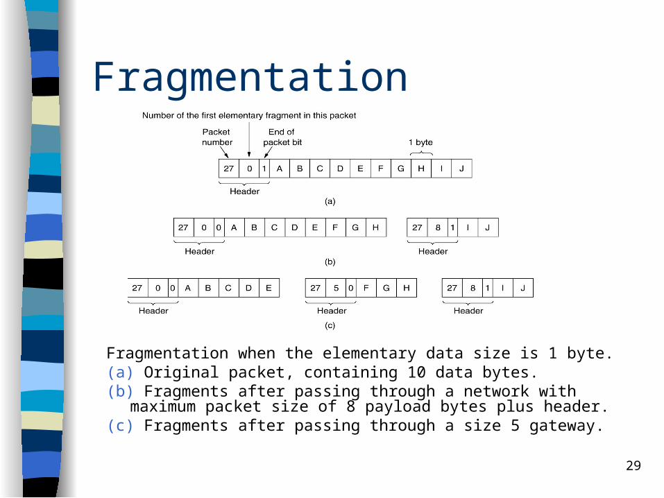
Fragmentation when the elementary data size is 1 byte.(a) Original packet, containing 10 data bytes.(b) Fragments after passing through a network with maximum packet
size of 8 payload bytes plus header.(c) Fragments after passing through a size 5 gateway.

30
Address issue
Main aspect in virtual network is a standard address format
Cannot use hardware address because different technology use different address format
Address format should independence to any address format of hardware address
Sending Host place internet destination address in packet/datagram
Router check destination address and send packet to destination
31
TCP/IP address
Addressing in TCP/IP defined by Internet Protocol (IP)
Each host assigned to a 32-bit number Called IP address or Internet address Unique to throughout Internet Each datagram contain IP address of
source and destination
32
IP address
Each IP address divided into two categories : network number (prefix) and host number (suffix)
Network number shows physical network in which computer connected
Host number shows unique number of computer at network
Address format enable routing to be efficient

33
Define IP address
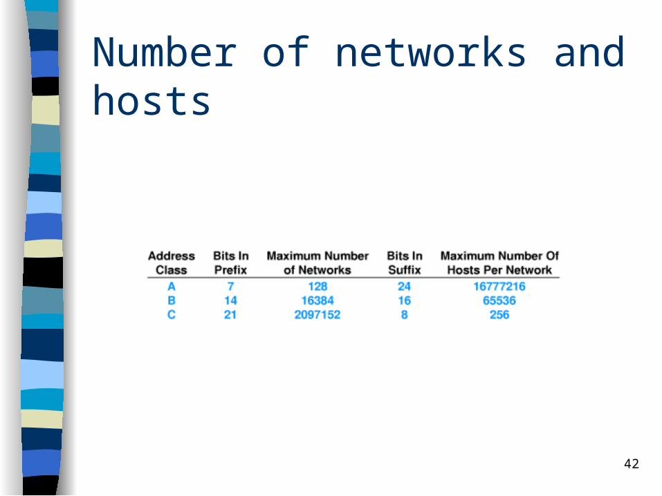
From 32-bit, some bit assigned to prefix and some to suffix
Prefix bigger , suffix smaller - many network, few host at network
Prefix smaller, suffix bigger - few network, many host at network
Because there are various technology, should allow smaller and bigger networks
34
Address classification
Various address format to allow both small and big prefix
Each format called an address class A class is identified through the first four
bit
35
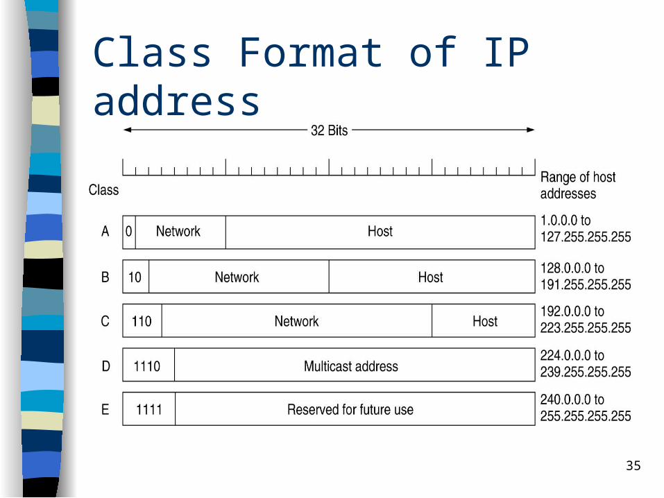
Class Format of IP address
36
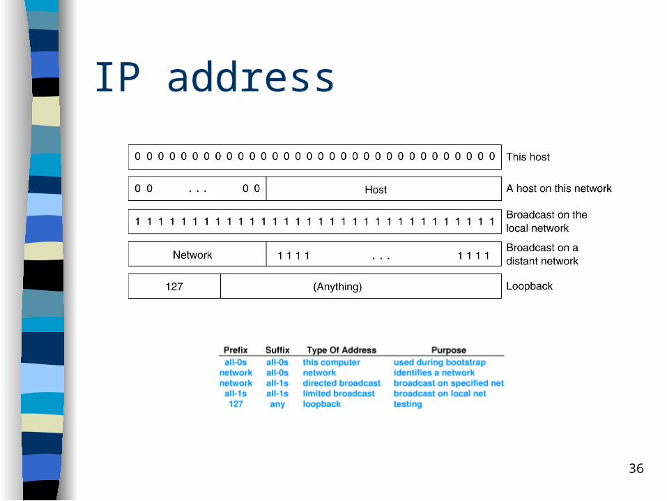
IP address
37
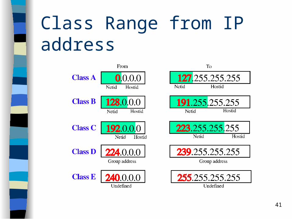
Using class IP
Class A, B and C are primary class– Used to normal host addressing
Class D for multicasting, a form of limited broadcast
Class E specify for future use
38
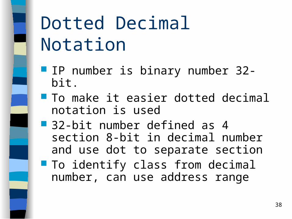
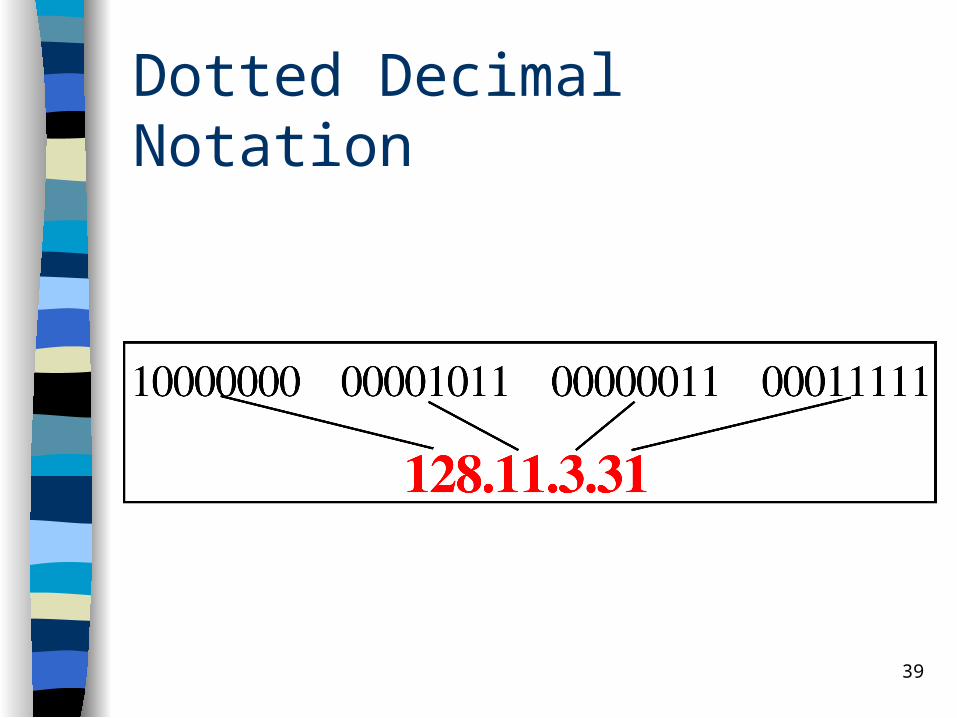
Dotted Decimal Notation
IP number is binary number 32-bit. To make it easier dotted decimal notation is
used 32-bit number defined as 4 section 8-bit in
decimal number and use dot to separate section
To identify class from decimal number, can use address range
39
Dotted Decimal Notation

40
Dotted Decimal Notation
41
Class Range from IP address
42
Number of networks and hosts

43
Example of class addressing
Example of assigning IP address to host
44
Subnet
Able to divide the network into sub-network Example: a platform has one IP address class
B assigned to network but has two or more physical network. Only local router know about various subnet and how to send data to it, other routers know only that there is just one network.
45
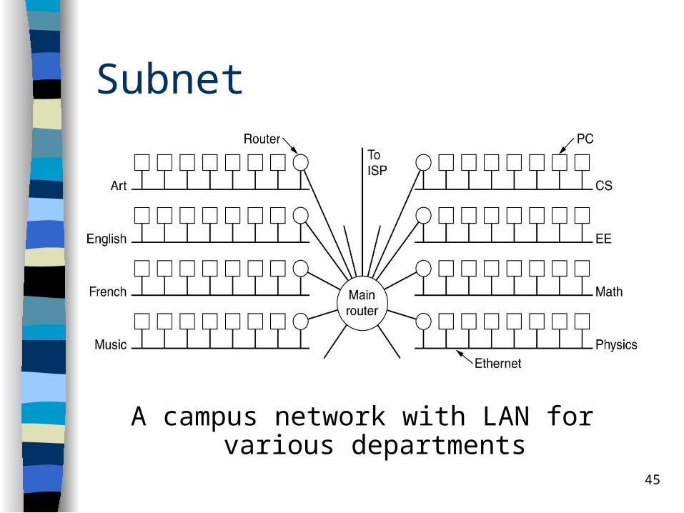
Subnet
A campus network with LAN for various departments
46
Subnet
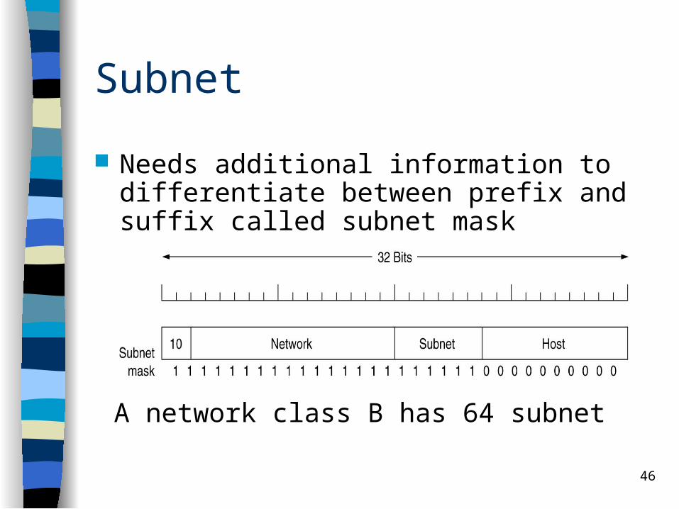
A network class B has 64 subnet
Needs additional information to differentiate between prefix and suffix called subnet mask
47
IPv6
128 bit address Head is more easier More service supports Security
48
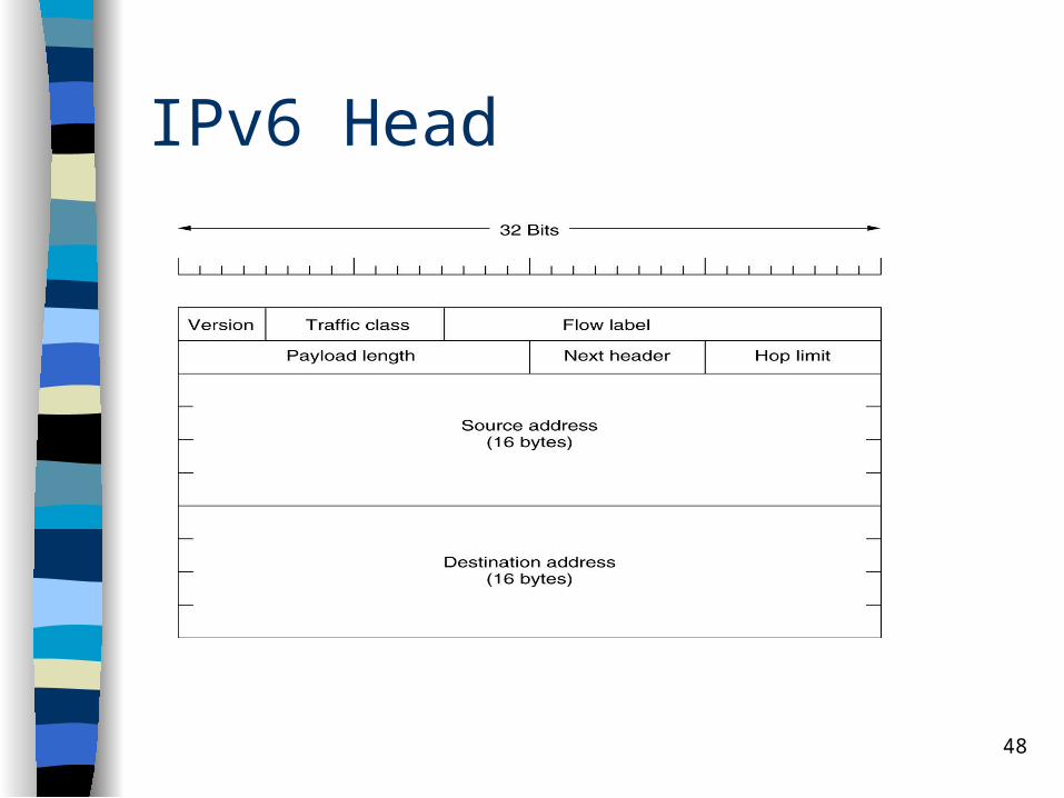
IPv6 Head
49
Internet control protocols
As addition to IP, Internet network layer has several control protocol :– Address Resolution Protocol (ARP)– Reverse Address Resolution Protocol (RARP)– Internet Control Message Protocol (ICMP) – Internet Group Management Protocol (IGMP)
50
Address Resolution Protocol (ARP)
Connection between host using IP address, but connection at data link layer using MAC address
This protocol used for finding MAC address for NIC that used by host with certain IP
Send request by broadcast – Host with IP will response
51
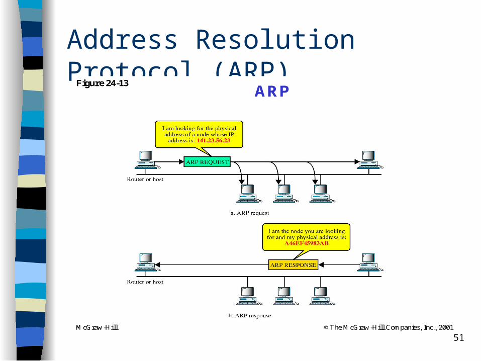
Address Resolution Protocol (ARP)
McGraw-Hill ©The McGraw-Hill Companies, Inc., 2001
Figure 24-13ARP
52
Reverse ARP (RARP)
Normally used by diskless computer. When it is booted from ROM, MAC address is known and want to know its IP address.
It can only be used in the same segment.
53
Internet Control Message Protocol (ICMP)
Used for configuration and IP networking (due to unreliability of IP)
Can give feedback about network problems
Type of message– Destination unreachable– Time to live (TTL) exceeded– Parameter problem (header unknown)
54
Internet Control Message Protocol (ICMP)
– Redirection– Response to request ( ping packet) – Response to request with time feedback (ping
needs time info (timestamped)
Use IP, so it can act by its own– Example of instruction that used ICMP
• Ping and Traceroute
55
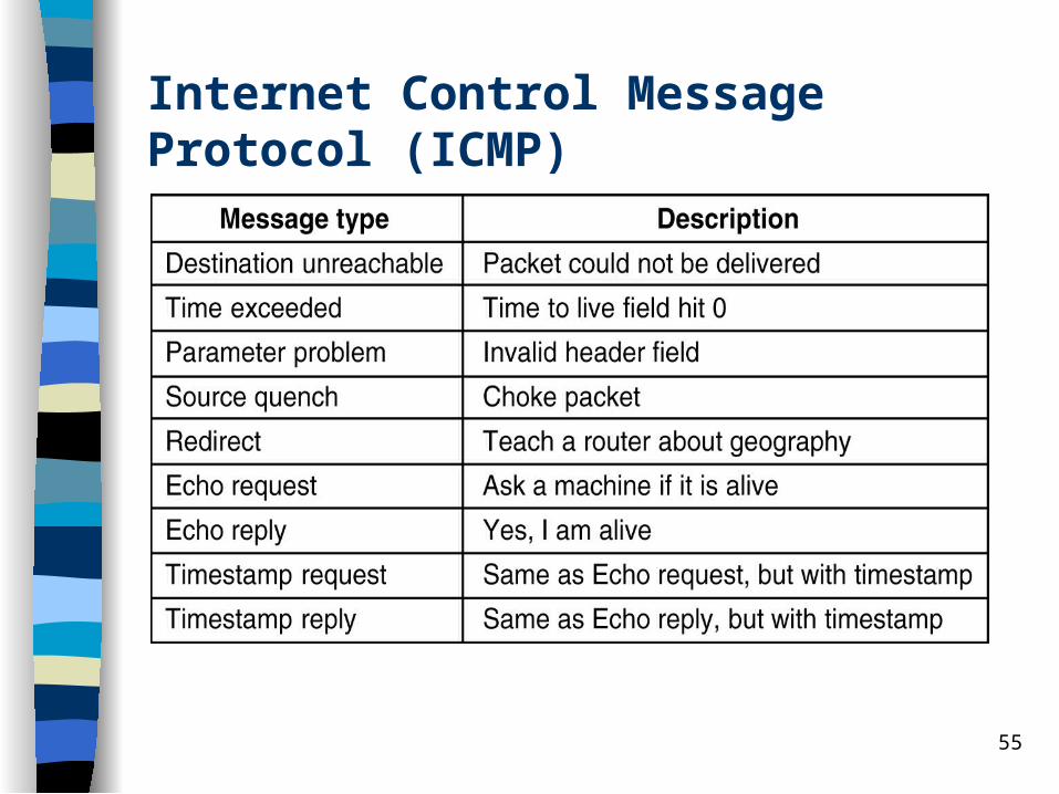
Internet Control Message Protocol (ICMP)

56
Internet Group Management Protocol (IGMP) The IP protocol can be involved in two types of The IP protocol can be involved in two types of
communication: unicasting and multicasting. communication: unicasting and multicasting. IGMP is one of the necessary, but not sufficient, IGMP is one of the necessary, but not sufficient,
protocols that is involved in multicasting.protocols that is involved in multicasting. IGMP is a companion to the IP protocol.IGMP is a companion to the IP protocol.

57
IGMP
There are two phases : – Phase 1 : when a host become a member
of a multicast group, it send a IGMP message to multicast group address to declare its membership. Local multicast router receives message and inform member information to other multicast router in internet
58
IGMP
– Phase 2 : because the membership is dynamic, multicast router periodically should poll for host in local network to certify whether any host is still active or not. If not active, inform to other multicast router.