1 impeccable circuitsimpeccable circuits anita aghaie, amir moradi, shahram rasoolzadeh, aein rezaei...
TRANSCRIPT

1
Impeccable CircuitsAnita Aghaie, Amir Moradi, Shahram Rasoolzadeh,
Aein Rezaei Shahmirzadi, Falk Schellenberg, Tobias Schneider
Abstract—By injecting faults, active physical attacks pose serious threats to cryptographic hardware where Concurrent Error Detection(CED) schemes are promising countermeasures. They are usually based on an Error-Detecting Code (EDC) which enables detectingcertain injected faults depending on the specification of the underlying code. Here, we propose a methodology to enable correct,practical, and robust implementation of code-based CEDs. We show that straightforward hardware implementations of givencode-based CEDs can suffer from severe vulnerabilities, not providing the desired protection level. In particular, propagation of faultsinto combinatorial logic is often ignored in security evaluation of these schemes. First, we formally define this detrimental effect anddemonstrate its destructive impact. Second, we introduce an implementation strategy to limit the fault propagation effect. Third, incontrast to many other works where the fault coverage is the main focus, we present a detailed implementation strategy which canguarantee the detection of any fault covered by the underlying EDC. This holds for any time of the computation and any location in thecircuit, both in data processing and control unit. In short, we provide practical guidelines how to construct efficient CED schemes witharbitrary EDCs to achieve the desired protection level. We practically evaluate the efficiency of our methodology by case studiescovering different symmetric block ciphers and various linear EDCs.
F
1 INTRODUCTION
Small embedded devices are ubiquitous and receive partic-ular attention in the Internet of Things (IoT). Often, suchdevices are expected to fulfill security relevant services likeauthentication or storage of private and sensitive data. Thecrux of the matter is an embedded device being in thehand of a potential attacker. This enables all sorts of phys-ical attacks on the implementation of some cryptographicscheme, independent of their mathematical security. Thegoal of our work is to protect a circuit against one classof such attacks: fault-injection attacks, first introduced byBoneh et al. [1]. Here, the attacker aims at disturbing thedevices’ regular execution so that an error occurs. Based ona subsequent mathematical analysis of the genuine and thefaulty response of the device, it might be possible to derivethe used secret.
An intuitive countermeasure to such attacks is to in-troduce redundancy by calculating twice, either in parallel(area redundancy or duplication) or consecutively (time re-dundancy) [2], [3]. When a fault is detected, the output isomitted or sensitive data is destroyed. Since the consistencyof information is checked simultaneously with the computa-
• Anita Aghaie, Amir Moradi, Shahram Rasoolzadeh, Aein Rezaei Shah-mirzadi, and Falk Schellenberg are with the Ruhr University Bochum,Horst Gortz Institute for IT-Security, Germany.E-mail: [email protected] Schneider is with NXP Semiconductors Austria GmbH. The major-ity of his contribution was performed while he was with Ruhr UniversityBochum and UC Louvain. E-mail: [email protected]
The work described in this paper has been supported in part by the GermanFederal Ministry of Education and Research BMBF under grant number16KIS0602 VeriSec, the Deutsche Forschungsgemeinschaft (DFG, GermanResearch Foundation) under Germany’s Excellence Strategy - EXC 2092CASA - 390781972 and the project 406956718 SuCCESS, the EuropeanUnions Horizon 2020 program under project number 645622 PQCRYPTO,and the European Commission through the ERC project 724725 (acronymSWORD).
tion, such schemes are usually denoted as Concurrent ErrorDetection (CED).
Error Detecting Codes (EDCs) seem to be a promisingapproach to counter strong adversaries as they can be easilyadjusted by increasing the minimum distance of the code,i.e., the maximum number of faults that the code can detect.However, the implementation of code-based CED suffersfrom certain problems: (a) the limited security of the so-phisticated codes in practice, and (b) the higher complexitycompared to plain duplication.
In theory, the security of a code-based CED is defined bythe parameters of the employed code. In practice, however,it strongly depends on how the CED scheme is imple-mented. It is a trivial observation that one faulty gate canaffect multiple subsequent gates. This effect which we laterdefine as fault propagation can result in degradation of theachieved error-detecting capability compared to the onedefined by the underlying code. While this is not consideredas an issue for duplication schemes, it can severely reducethe security of other more complex codes as we show laterin this article. We present examples where a single faultygate suffices to bypass advanced code-based CED schemes.
Contributions. In this paper, we present a methodologywhich enables a secure and practical implementation ofcode-based CED schemes in the presence of fault propagation,which we first formally define and highlight its conse-quences on the error-detection capability. Then, we presentdifferent strategies to limit its effect, each of which mitigatesthe security issue while having different area overheads.Consecutively, we define an adversary model, who is able toinject faults at a bounded number of cells at any location ofthe circuit (including data processing and control modules).On its basis, we present guidelines how to implement code-based CED in hardware circuits in such a way that thedetection of faults fitting into the considered model is guar-anteed. We further cover every signal and component in

2
our constructions including computational modules, finitestate machine, and controlling signals. Indeed, it would notmatter where the faults are injected, they must be detectedas long as they are fitting to the considered bounded model.We in fact define requirements to guarantee the securityagainst fault attacks making use of up to certain numberof faulty cells.
In order to explore the effectiveness of our methodology,we consider several case studies based on symmetric blockciphers including PRESENT [4], Skinny [5], Midori [6],GIFT [7], LED [8], SIMON [9] and AES [10] and variouslinear EDCs with different distances to examine the area-overhead and throughput of our constructions by means ofan ASIC standard cell library.Related Works. There is an extensive body of work relatedto the design and implementation of CEDs. In some, theproblem of fault propagation was already identified andsome basic countermeasures were discussed. Below, webriefly recall related works and indicate their limitations.
Parity is often used as an EDC for CED schemes. Theauthors of [11] identified the fault propagation issue and asa solution suggested to divide the circuit, yet only withinthe context of parity-based schemes. In further previously-published articles [12], the use of other more sophisticatedlinear codes for CED schemes was proposed, includinga formal verification of the error detecting capabilities.However, in most cases only a software implementationwas considered, which limits its portability to hardwarecircuits. In [13], the authors explored how EDCs can be com-bined with Threshold Implementation (TI) [14] to constructan efficient hardware design resistant against both faultand side-channel attacks. Private Circuits II [15] is anotherapproach aiming at designing a circuit protected againstboth active and passive adversaries. While it does provideprovable security, the efficiency of its practical realization isquestionable as shown in [16]. Recently, two new combinedcountermeasures based on multiparty computation havebeen proposed in [17], [18]. Practical investigation of [17]which is based on a software implementation shows a highoverhead. For CAPA [18], the authors introduce a newformal adversary model including both active and passiveattacks. Their approach is not affected by fault propagation,as it relies on the hardness of forging a valid MAC tagfor fault resistance. The problem of fault propagation wasalso discussed in [19], where Timing Violation VulnerabilityFactor (TVVF) as a metric to evaluate the security of a givencircuit was defined. It provides a good measure to comparethe security of different circuits, but it is limited to a veryspecific type of attacks.
2 PRELIMINARIES
2.1 Fault Injection AttacksFor fault attacks, the device is intentionally operated out-side its specification so that some faulty output can beobserved. Based on a subsequent mathematical analysis ofthe faulty (and genuine) output, the adversary is able torecover the secret key [1]. Physical means to inject a faultinclude tampering with the supply voltage [20] or the clocksignal [21]. Both relate to timing violations while strongelectromagnetic pulses [22] can affect the target’s execution
as well. In contrast, optical fault injection [23] using laserbeams can scale down the focus to a single transistor.Advanced optical setup can even target multiple transistorsindependently [24].
In practice, all physical fault injection techniques incor-porate many parameters, e.g., the timing (clock cycle), thephysical intensity, the duration of the effect, the location(x/y) on the device and even the distance (EM) or focalplan (laser). This already lead to various approaches tryingto limit the parameters [25], [26].
Multiple properties can be derived how the target willbe affected. Most notably we can refer to its electrical effect,e.g., whether some internal value will be always set tological ‘1’ or always reset to logical ‘0’. Faults sometimes aremodeled as bit-flip, which is certainly useful to model bothset and reset faults. Another parameter is the area that willbe affected, i.e., a single transistor, more bits, or the entireregisters. A crucial aspect is the distribution of the resultingfaults as there is usually some form of bias [27], [28]. Con-sidering for example clock glitches or underpowering, thebits involved in the critical path will be the first becomingfaulty. For optical fault injections, only the exact area that issufficiently illuminated will be affected.
The vast majority of attacks on ciphers is based on com-paring a single or multiple faulty outputs to genuine onesrespectively, so-called Differential Fault Analysis (DFA) [29].However, there are multiple more “exotic” approaches thatdiffer in certain aspects or requirements: Fault SensitivityAnalysis [30], Differential Fault Intensity Analysis [27], Sta-tistical Fault Attacks [28], [31], etc. Using one or another ofsuch attacks, the implementations of different ciphers werefound to be vulnerable. In fact, DFA can be seen as a form ofdifferential cryptanalysis on some last rounds of the cipherdefined by a particular fault model.
An obvious generic countermeasure is to introduce someform of redundancy. This translates to repeating e.g., theencryption for time redundancy, or multiple encryptions inparallel for area redundancy. More sophisticated approachesemploy coding schemes instead of plain redundancy [12],[32], [33]. All CED schemes commonly check whether in-deed no fault occurred to enable the output.
2.2 Concurrent Error Detection Schemes
As depicted in Figure 1, a CED scheme usually includesthe original target algorithm A and its designated predictorA′. These predictors range from an exact duplicate of A inthe most basic case (i.e., duplication) to sophisticated code-based predictors (e.g., parity). To increase the performance,some predictors are designed to operate on a compressedmapping of INPUT, e.g., only one bit for parity. Depend-ing on A, such predictors may not be able to predict thecompressed mapping of the output of A. Hence, they mayrequire intermediate results from A during the computation.The result of A and A′ are checked in module C to detectpossible errors before transmitting OUTPUT. This structureis very generic and can be applied on different levels ofgranularity or types of redundancy.

3
Target
A
Predictor
A′
Check
C
input
output
. . .
Fig. 1. Basic Structure of concurrent error detection schemes.
Definition 1 (Fault Coverage). The fault coverage of a givenCED scheme C in a specific fault modelM is defined as the ratio
CovM(C) =ξ(C,M)
ψ(C,M),
where ψ(C,M) (resp. ξ(C,M)) stands for the number ofpossible (resp. detectable) faults of C adjusted to the distributionofM.
Such a metric to evaluate CED schemes has commonlybeen used in several related works, e.g., [34]. While ahigher fault coverage theoretically indicates a higher levelof protection, the practical security strongly depends onthe chosen fault model and its closeness to reality. Thismodel should be carefully adapted based on the assumedadversary to avoid under- or overestimating the coverage.
2.3 Error Detecting Codes
EDCs are an essential aspect of information theory and areoften used in CED schemes. In the following, we introducesome notions [35] related to linear codes which are relevantto our work.
Definition 2 (Linear Code). A binary linear [n, k]-code C withlength n and rank k is defined as a vector subspace over Fn2 whichmaps messages x ∈ Fk2 to codewords c ∈ C.
Definition 3 (Generator Matrix). A k × n-matrix G is agenerator matrix of an [n, k]-code C iff it consists of k basisvectors of C with length n. It can be used to map every messagex ∈ Fk2 to its corresponding codeword with x ·G = c ∈ C.
Definition 4 (Minimum Distance). The minimum distance dof a linear [n, k, d]-code C is defined as
d = min{wt (c1 ⊕ c2) | c1, c2 ∈ C, c1 6= c2
},
where wt : Fn2 7→ N denotes the Hamming weight.
The error detection capability of a linear code C dependson its minimum distance, i.e., the larger the distance themore errors can be detected.
Lemma 1. An [n, k, d]-code C can detect erroneous codewordsc′ = c⊕ e iff e /∈ C.
In particular, all error vectors e 6= 0 with wt(e) ≤ u =d− 1 are detected.
Definition 5 (Systematic Code). The generator matrix G of asystematic code C is of the form G = [Ik|P ] where Ik denotesthe identity matrix of size k.
Due to the structure of the generator matrix of systematiccodes, each codeword c contains the message x paddedby check bits x′, i.e., c : 〈x, x′〉. The check bits can beeasily generated using the matrix P as x′ = x · P . Thisenables a simple split of the data paths between messageand check bits as depicted in Figure 1. Therefore, the originalimplementation of the target operation A can stay as it is,while it is extended with the predictors A′ for the check bits.
Example 1 (Parity). As a common approach CED scheme [32],[33], the check bits x′ consist of only one additional bit, and therequired extra logic is rather small1. This leads to a [k + 1, k, 2]-code with an error-detecting capability of u = 1 bit.
Example 2 (Multiple Executions). Another common CEDschemes is to simply run the target algorithm multiple times (byeither time or area redundancy) [3], [37]. It turns to a [λk, k, λ]-code where λ denotes the number of executions of the algorithm(e.g., λ = 2 for duplication). The error-detecting capabilityu = λ − 1 can be straightforwardly improved by increasing λat the cost of multiplying the overhead byλ.
It has also been proposed to use non-linear codes toimprove the fault coverage [38], [39]. However, they mayhave no benefits over linear codes in some scenarios [36].Nevertheless, many of the issues discussed in this paperare based on the linear property of the underlying code.Therefore, we particularly omit non-linear codes in ourconstructions.
3 CONCEPT
The effectiveness of faulty-detection property of CEDschemes heavily relies on the specific parameters of theunderlying code. While the rank directly affect the size ofthe code |C|, the distance determines the higher bound forthe Hamming weight of the detectable error vectors. Manyproposed CED schemes are evaluated either by practical ex-periments limited by the capabilities of the evaluator [40] oronly theoretically in the common uniform fault model [32].In such a model, the error vector e ∈ Fn2/{0} follows auniform distribution, i.e., Pr(e) = 1
2n−1 .
Example 3 (Fault Coverage in the Uniform Model). For anarbitrary [n, k, d]-code C, an error vector e cannot be detected bythe CED iff e ∈ C. This translate to the following fault coverageconsidering a uniform fault model, so-called U .
CovU (C) = 1− | Fk2/{0} |
| Fn2/{0} |=
2n − 2k
2n − 1. (1)
Since CovU is independent of the code distance d, every code witha constant length and rank provides the same fault coverage, e.g.,an [8, 4, 2]-code C1 and an [8, 4, 4]-code C2 both have the faultcoverage of CovU (C1) = CovU (C2) = 0.94.
However, most fault distributions in practice, requiredby certain fault attacks, should have a specific bias [27],
1. The predictors can have a high complexity, which diminishes theoverhead advantage [36].

4
[28], [41]. Furthermore, the fault coverage can be drasticallyreduced if the fault distribution changes, e.g., attacking aduplication CED scheme by injecting a symmetric fault, i.e.,the same fault is injected into A and A′ when A′ = A. Hence,the distance of the code becomes an important factor for theeffective fault coverage, e.g., when the adversary has highly-accurate fault-injection facilities (e.g., a laser beam [42], [43]).
It is noteworthy that in some hybrid schemes when bothencryption and decryption functionalities are supported bythe circuit, the correctness of the computation can be exam-ined by checking whether the decrypted ciphertext matchesthe original plaintext, or even in a round-based fashion [44].This for sure increases the fault detection capability, butcertain symmetric faults still cannot be detected, e.g., thesame fault injected at the input of round 9 of AES encryptionand at the output of round 1 of AES decryption.
The stronger an adversary is assumed to be, the morecare needs to be taken when implementing a specific CEDscheme. In the following, we first introduce our adversarymodel. Then, we highlight the practical issue of fault prop-agation for code-based CED schemes and discuss criticaldesign choices, which strongly improve the fault coverageof CED in practice. We try to formalize the problem andprovide a guideline how CED schemes should be integratedinto an implementation of cryptographic algorithms.
3.1 Adversary ModelWe assume an adversary model similar to [15], i.e., thecomputation of the circuit is partitioned in clock cycles andthe adversary can adaptively make t wires faulty (toggle)per clock cycle. We assume that if a wire is faulty, all itsconnections are also faulty. In other words, we exclude thecases where the attacker is able to cut a connection and makecertain wire(s) faulty without affecting the other wires ofthe same connection. Since each wire is the output of a cell(either a gate or a register), we can model every fault on awire as a fault on the corresponding cell.
Definition 6 (Univariate Adversary Model Mt). In a givensub-circuit, the adversary is able to make up to t cells faulty atone clock cycle of the entire operation of the algorithm, e.g., a fullencryption.
Definition 7 (Multivariate Adversary ModelM∗t ). Here, theMt adversary model is extended to allow the attacker to injectsuch bounded faults at multiple clock cycles.
We first focus on univariateMt model and present tech-niques to construct a circuit providing full fault coverage.Afterwards, we give a solution to turn anMt-secure circuitto its multivariateM∗t -secure variant.
Definition 8 (Checkpoint). A checkpoint c monitors the cor-rectness of the state of the circuit at a specific point in thecomputation.
Figure 2 depicts the concepts of checkpoints for an (a)univariate and (b) multivariate adversary with t = 2 (thered cells and wires indicate the faulty ones). While theunivariate adversary can make at most two cells faulty inone specific clock cycle (gates no. 1 and 3), the multivariateadversary is able to hit at most two cells per clock cycleleading to all output wires in the circuit faulty (gates no. 1
Checkpoint
Checkpoint
c1
c2
1
2
3
(a) univariate
1
2
3
45
Clock Cycle i
Clock Cycle i+ 1
(b) multivariate
Fig. 2. Fault injection by anMt=2 andM∗t=2 adversary.
and 3 in the first clock cycle, and gates no. 4 and 5 in thesecond clock cycle).
In order to conduct a successful DFA, the faults mustfit into a particular model, e.g., one-bit fault in a byte, or asingle-byte fault in a 16-byte state. For precise models (e.g.,single-bit faults) the attack needs a few faulty outputs torecover the secret (for example 2 faulty ciphertexts in caseof AES encryption). In contrast, for more general models thenumber of required faulty outputs increases rapidly [45].The goal of EDC-based CED schemes is to set a relativelyhigh bound for t, i.e., the attacker has to make more thant cells faulty to obtain a faulty output, hence hardening thecorresponding DFA attack.
3.2 Fault Propagation
If an input of a gate in the circuit is faulty, its output mightbe faulty as well depending on the type of the gate and thevalue of the other inputs. This phenomenon is propagatedthrough the circuit and as a result an Mt-bounded adver-sary achieves t+ δ ≥ t faulty cells, where δ ≥ 0 depends onthe t chosen cells and the other cells involved in the circuit.We formally define fault propagation as follows while it hasbeen briefly discussed in [11], [13], [33].
Definition 9 (Fault Propagation). We assume the worst casefor fault propagation, i.e., one faulty input of a gate results ina faulty output. Hence, in the presence of fault propagation it ispossible for an Mt-bounded adversary to achieve tp faulty gateswith
t ≤ tp ≤ |G|,
where |G| denotes the number of gates in the underlying circuit.
This has serious implications as the distance of theunderlying code does not provide a reliable bound for tanymore. In particular, this bound is valid for an adversarywho can only make faults at the check points. Againstan Mt adversary, however, who can arbitrarily make cellsfaulty, the distance of the code does not define a meaningfulbound.

5
1
2
3A A′
(a)
1
2
3
4
A1 A′1
A2 A′2
(b)
1 2
3A A′
(c)
Fig. 3. Realization of T protected with the parity [5, 4, 2]-code. (a) undetectable fault with t = 1 faulty cells (red), (b) all t = 1 faulty cells detectablewith an extra checkpoint, (c) all t = 1 faulty cells detectable with forced independence.
Example 4 (Parity with Fault Propagation). Let assume a[5, 4, 2]-code Cparity with a generator matrix
Gparity =
1 0 0 0 10 1 0 0 10 0 1 0 10 0 0 1 1
= (I | Pparity) .
Let also suppose a circuit realizing the function T : F42 7→ F4
2
which is supposed to be protected by such a CED. Exemplary, weconsider a linear function T (x) = x · L with
L =
1 0 0 00 1 0 00 1 1 00 1 1 1
.
Such a protected circuit, including A and A′, is depicted inFigure 3(a) consisting of three XOR gates. A realizes T (x) = x·Land A′ is formed by x ·L ·Pparity . The checkpoints are also placedat the input and output of the circuit. In the uniform fault model,based on Equation (1) its fault coverage is derived as
CovU (Cparity) =25 − 24
25 − 1= 0.52.
Since the code has a distance of d = 2, we restrict the adversary tot = d − 1 = 1 cells. The code is indeed able to detect all possiblefaults injected at the gates whose output is exclusively connectedto the checkpoints (e.g., Exclusive OR (XOR) gates 2 and 3 inFigure 3(a)). Referring to such a fault model as Tt=1, it results in
CovTt=1(Cparity) = 1.
However, in the presence of fault propagation there are multiplepossibilities that the adversary can increase the number of faultygates and thus create an undetectable faulty state. One exampleis shown in Figure 3(a), where only one fault is injected on theXOR gate 1. It propagates through the XOR gate 2, and twofaulty signals arrive at the checkpoint, i.e., a state undetectable byparity. RepeatingMt=1-bounded faults on all gates of the circuitresults in
CovMt=1(Cparity) = 2/3.
4 METHODOLOGY
In this section we present our solutions to provide full faultcoverage under anMt adversary model.
4.1 Extra Checkpoints
One strategy to restrict the impact of fault propagation is theinclusion of extra checkpoints in the circuit. By splitting thecircuit in smaller sub-circuits divided by checkpoints, thiseffect can be damped assuming each sub-circuit containsfewer gates than the whole design. This concept can be seenas the inclusion of registers in TIs of composed functions toprevent the propagation of glitches [14].
An interesting question is at which points in a circuitthe extra checkpoints need to be inserted. An approach isto decompose T (.) into multiple sub-functions as T (x) =Tl ◦ . . . ◦ T1(x) with a checkpoint between every Ti(.) andTi+1(.). This limits the fault propagation if each of the sub-functions is less sensitive to fault propagation. To measurethe sensitivity, it can be seen that the fault cannot propagateif the circuit realizing a sub-function Ti(.) has a depth of1, i.e., there is no gate in the underlying sub-circuit whoseinput is derived from another gate of the same sub-circuit.
Lemma 2 (Preventing Fault Propagation with Checkpoints).Fault propagation can be completely prevented by inserting acheckpoint at the output wires of all gates of a given circuit. Toachieve this, the state at each checkpoint has to be a valid codewordunder the employed code.
Proof. By checking every wire of every gate output, weprevent the propagation of one detectable faulty gate toundetectable multiple faulty gates. Therefore, one faultygate can only result in maximum one faulty wire at thefollowing checkpoint enforcing tp = t.
Example 5 (Parity with Extra Checkpoints). As a genericstrategy, adding checkpoints can result in extra combinatoriallogic as shown in Figure 3(b) for our previous parity example.The inclusion of an extra checkpoint prevents harmful faultpropagation and ensures the error-detection capability for t = 1.

6
To this end T (x) = x · L (see Section 3.2) is decomposed toT = T2 ◦ T1 by
L1 =
1 0 0 00 1 0 00 0 1 00 0 1 1
, L2 =
1 0 0 00 1 0 00 1 1 00 0 0 1
.
Obviously, Ai∈{1,2} realizes Ti(x) = x ·Li and A′i is formed byx · Li · Pparity . Excluding the extra checkpoint, this comes at thecost of one additional XOR. Nevertheless, the new design Cparity
provides the desired fault coverage of
CovTt=1(Cparity) = CovMt=1
(Cparity) = 1.
4.2 Forced Independence
As an observation, duplication (or generally the realizationof the target function as λ instantiations of A) providessecurity against an Mt=λ−1-bounded adversary even withfault propagation.
Independence Property. The above observation can begenerically applied to other codes as well. Let us assumethe target function T : Fk2 7→ Fq2 which maps the input xto a q-bit output y : 〈y1, . . . , yq〉. The function T (x) = y isphysically realized by q component-circuits each of whichrealizing a component-function T i : Fk2 7→ F2 in such a waythat ∀i, T i(x) = yi. Such a set of component-circuits arecalled independent if no gate is shared between every twocomponent-circuits.
∀i, j; i 6= j Gi ∩ Gj = ∅,
where Gi stands for a set of gates implementing thecomponent-function T i(.).
Lemma 3 (Preventing Fault Propagation with Forced In-dependence). Given a function T : Fk2 7→ Fq2, a physicalimplementation realized by a set of q independent component-circuits does not suffer from fault propagation. Hence, tp = t if acheckpoint is placed at the output of T (.).
Proof. Based on the assumption that the component-circuitsare distinct and do not share any resources, it is not possiblefor a faulty wire in T i to traverse to T j 6=i. Therefore, onefaulty gate can maximally affect one output wire of T (.),since each T i(.) computes only one unique output bit ofT (.). This implies that every t faulty gates in the entire setof component-circuits can make at most t output wires ofT (.) faulty. Therefore, tp = t.
This strategy is shown in Figure 4. Since the hardwaresynthesizers usually optimize the given design (e.g., bysharing the identical components to achieve lower area),particular attention should be paid to avoid such opti-mizations2. Otherwise, the independence property might beviolated.
Example 6 (Parity with Forced Independence). For our run-ning example, we consider A and A′ as one function T : F5
2 7→ F52.
Based on Lemma 3, it is required to implement T as five distinct
2. In common HDL designs, it can be done by instantiating a uniquecomponent for each component-function, and forcing the synthesizerto keep the hierarchy.
A A′
Fig. 4. Forced independence of the target algorithm A and its predictorA′.
component-functions which do not share any resources. The re-sulting design Cparity is depicted in Figure 3(c). Compared tothe former example, forced independence suffices with only onecheckpoint which makes it more efficient than Cparity , whileproviding the same fault coverage of
CovTt=1(Cparity) = CovMt=1
(Cparity) = 1.
4.3 CombinationEach aforementioned solution comes at the cost of higherarea specially for complex cryptographic algorithms. There-fore, we propose to utilize a hybrid approach in three stepsfor a given target function T (.).
1. Decompose T : Fk2 7→ Fq2 into multiple sub-functionsTi : Fki2 7→ Fqi2 of a less complexity.
Considering a classical symmetric cipher, each sub-functionTi(.) reflects a fundamental module of the cipher (e.g.,substitution, diffusion, and key addition).
2. Split each Ti(.) into multiple smaller sub-functionsTi,j : Fki,j2 7→ Fqi,j2 with
∑j ki,j = ki and
∑j qi,j = qi.
A basic split in a majority of symmetric ciphers follows thecipher’s structure, e.g., each sub-function Ti,j represent anS-box on nibbles or MixColumns on words.
3. Implement each sub-function Ti,j fulfilling the independenceproperty, and place a checkpoint at their output.
This step benefits from the small input size of Ti,j . However,a decomposition (step 1) that is too fine would suffer fromthe basic problem of frequent checkpoints. Therefore, it isimperative to find a balance between the two strategiesadjusted to the target function T (.).
4.4 ApplicationIn order to clarify the application of our strategies in a code-based CED scheme, we consider an exemplary algorithmrealized by a sequential circuit depicted in Figure 5(a) con-sisting of a register which loads the INPUT at the start of theoperation (triggered by rst signal) and performs the functionT (.) repeatedly till the OUTPUT is taken from the register3.
3. Finite State Machine (FSM) is not shown.

7
rst
T
Input
Output
(a) original
rst
T
Input
F
OutputC
rst
Input′
T ′
C ′
×k ×m
A A′
(b) F (.) injective or transparent
rst
T
Input
F
OutputC
rst
Input′
T ′
C ′
×k ×m
A A′
(c) F (.) non-injective and non-transparent
Fig. 5. Our construction with respect to application of an EDC.
For the sake of simplicity we suppose that the bit-lengthof INPUT, register, and T (.) input and output is a multipleof k bits. The application of an [n, k, d]-code would leadto transforming every k-bit chunk x to an n-bit codewordc = [x | x′]. Hereafter, we refer to the application of matrixP on x to derive the redundant part x′ by F : Fk2 7→ Fm2as F (x) = x · P = x′, where m = n − k denotes the bit-length of the redundancy. Without losing the generality, weuse k and m (or ×k and ×m) to refer to the bit-length ofthe message and redundancy, respectively. In the followingwe distinguish two different cases and explain how theunderlying EDC is applied.
F : an injective function or transparent to TIf the redundancy size is at least as large as the message size(n ≥ 2k) and the function F (.) is injective, the redundancypart of the circuit (noted beforehand by A′) can operate onx′ independent of x, as shown in Figure 5(b). The redundantfunction T ′(.) is also trivially achieved as T ′ = F ◦T ◦F−1.Both T (.) and T ′(.) should be implemented following theforced independence, and a checkpoint is placed at the inputof the T (.) marked by c and c′ in Figure 5(b). It is indeedessential to place the checkpoint at the input of any functionimplemented by the forced independence. Otherwise, if thecheckpoints are moved to the output of T (.), the faultsinjected at the register cells would potentially propagate tomultiple output bits of T (.). It should be noted that since themultiplexer and the register (see Figure 5(b)) independentlyoperate on each bit of the T (.) output, they do not affect theindependence property. Therefore, any fault injected at T (.)fitting toMt=d−1, is detected at the checkpoint in the nextclock cycle.
If F (.) is not injective, for some particular functionsT (.) it is still possible for T ′(.) to operate only on x′
(Figure 5(b)). Since any intermediate value of the circuitshould be a valid codeword, if x′ = F (x), the output〈T (x) , T ′ (x′)〉 should also form a valid codeword. Thisimplies that T ′(x′) = F (T (x)), i.e.,
T ′ ◦ F = F ◦ T. (2)
Given T (.) and F (.), it can be examined if there existssuch a function T ′(.) fulfilling the above condition. In manycases, specially in SPN block ciphers, the linear layer usesmultiplication in F2k , i.e., T : F2k 7→ F2k in such a way that
T (x) = a • x with constant a ∈ F2k . In the following weshow that if a is a primitive element (then a 6= {0, 1}), thereexists no such a function T ′(.) fitting to Equation (2).
Lemma 4. Let T : F2k 7→ F2k that T (x) = a • x ismultiplication with primitive element a ∈ F2k , and let F :F2k 7→ F2m be any linear non-injective function. Then, thereis no T ′ : F2m 7→ F2m such that F ◦ T = T ′ ◦ F .
Proof. Since F (.) is a linear function, among its inputs thereexist 2c (with c ≥ k −m) values which are mapped to zero.In other words, there are 2c − 1 ≥ 1 nonzero roots for F (.).Let u be one of them, i.e., F (u 6= 0) = 0. Now assume thatthere exists a T ′(.) function which F ◦ T = T ′ ◦ F . As bothF (.) and T (.) are linear, T ′(.) is also linear. This results toT ′(0) = 0. Hence, we have
F ◦ T (u) = T ′ ◦ F (u) = T ′(0) = 0 ⇒ F (a • u) = 0,
which means a • u is another nonzero root of F (.). Byrepeating above equation, we find out that for any i ≥ 0,ai •u is a nonzero root of F (.). Since T (.) is a multiplicationwith primitive element in F2k , none of (ai • u, aj • u) withi 6= j and i, j < 2k − 1 are equal to each other. Hence,we have 2k − 1 nonzero roots for F (.) which means thatany x ∈ F2k is a root for F (.) (i.e., ∀x, F (x) = 0) that is incontrast with our assumption that F (.) is an arbitrary linearfunction.
If T (.) is a multiplication with a = 0/1 in F2k , theredundant counterpart T ′(.) is a multiplication with thesame constant in F2m . This for example holds for the linearlayer of several block ciphers including Midori [6], Skinnyand Mantis [5].
F : a non-injective function and non-transparent to TIn such cases, T ′(.) needs to receive the original data x tobe able to compute T ′(x) = F ◦ T (x). The correspondingconstruction is shown in Figure 5(c), where the only dif-ference to the former case is how the T ′(.) is realized. Itis noteworthy that the implementation of T ′(.) should alsofulfill the independence property.
OptimizationThe decomposition of T = T2 ◦ T1 would generally leadto one of the constructions shown in Figure 6, where acheckpoint is placed between the sub-functions.

8
rst
T1
T2
Input
F
OutputC1
C2
rst
Input′
T ′1
T ′2
C ′1
C ′2
×k ×m
A A′
(a) F (.) injective or transparent
rst
T1
T2
Input
F
OutputC1
C2
rst
Input′
T ′1
T ′2
C ′1
C ′2
×k ×m
A A′
(b) F (.) non-injective and non-transparent
rst
T1
T2
Input
F
OutputC1
C2
rst
Input′
T ′1
T ′2
C ′1
C ′2
×k ×m
A A′
(c) F (.) non-injective but transparent to T2(.)
Fig. 6. Our construction with respect to application of an EDC with decomposition.
Theorem 1. If T2(.) is a linear function represented by matrixL with elements in F2k , the extra check c2 and c′2 between T1(.)and T2(.) is not required if L is formed by only 0/1.
Proof. Below, we represent an intermediate value of thecircuit by x (resp. x′) as s equally-sized k-bit chunks〈x1, . . . , xs〉 (resp. m-bit chunks 〈x′1, . . . , x′s〉). Due to theindependence property, any fault injected at t cells of asub-function is modeled by an additive error vector eat its output. We use the notation e1 = 〈e1,1, . . . , e1,s〉,e′1 =
⟨e′1,1, . . . , e
′1,s
⟩, e2 = 〈e2,1, . . . , e2,s〉 and e′2 =⟨
e′2,1, . . . , e′2,s
⟩for the corresponding error vectors of in-
jected faults in T1(.), T ′1(.), T2(.) and T ′2(.), respectively. Thecheck at c1 and c′1 examines the below equality:
F (T2(x⊕ e1)⊕ e2)?= T ′2(x
′ ⊕ e′1)⊕ e′2,
where x denotes the fault-free output of T1(.), i.e., the inputof T2(.). Since x′ = F (x) and F ◦ T2 = T ′2 ◦ F , the aboveequation is simplified to
F (T2(x))⊕ F (T2(e1))⊕ F (e2) ?= T ′2(x
′)⊕ T ′2(e′1)⊕ e′2 ⇒F (T2(e1)⊕ e2)
?= T ′2(e
′1)⊕ e′2 (3)
Considering an Mt=d−1 adversary model, wt(e1) +wt(e′1) + wt(e2) + wt(e′2) < d. In order to detect it, therelation in Equation (3) should be unequal. It means
∀e1, e′1, e2, e′2 ;
0 < wt(e1) + wt(e′1) + wt(e2) + wt(e′2) < d =⇒F (T2(e1)⊕ e2) 6= T ′2(e
′1)⊕ e′2
which equally means
∀e1, e′1, e2, e′2 ; F (T2(e1)⊕ e2) = T ′2(e′1)⊕ e′2 =⇒
wt(e1) + wt(e′1) + wt(e2) + wt(e′2) ≥ d ∨wt(e1) = wt(e′1) = wt(e2) = wt(e′2) = 0 (4)
We define T2(.) and T ′2(.) as
T2(x) = 〈x1, · · · , xs〉 · L , T ′2(x) = 〈x′1, · · · , x′s〉 · L′
L =
L1,1 L1,2 · · · L1,s
L2,1 L2,2 · · · L2,s
......
. . ....
Ls,1 Ls,2 · · · Ls,s
, L
′ =
L′1,1 L′1,2 · · · L′1,s
L′2,1 L′2,2 · · · L′2,s
......
. . ....
L′s,1 L′s,2 · · · L′s,s
,
where eachLi,j andL′i,j are binary k×k andm×mmatrices,respectively, and
∀i, j Li,j · P = P · L′i,j .
Using above definitions, Equation (3) can be written asfollowing s equations.
( s⊕
j=1
e1,j · Lj,1 ⊕ e2,1)· P =
s⊕
j=1
e′1,j · L′j,1 ⊕ e′2,1
...( s⊕
j=1
e1,j · Lj,s ⊕ e2,s)· P =
s⊕
j=1
e′1j · L′j,s ⊕ e′2,s
Let us denote αi =⊕s
j=1 e1,j ·Lj,i⊕e2,i and βi =⊕s
j=1 e′1,j ·
L′j,i ⊕ e′2,i. If ∀i αi = 0, then T2(e1)⊕ e2 = 0. It means thatthe output of T2(.) is fault free, hence not useful for theadversary. Therefore, we can conclude that
∀e1, e′1, e2, e′2 ; F (T2(e1)⊕ e2) = T ′2(e′1)⊕ e′2 =⇒
e2 = T2(e1) ∨ ∃i; αi 6= 0.
Without loss of generality, we consider that there exists an ifor which αi 6= 0 and βi = αi · P . For an [n, k, d]-code, wealready know that for any nonzero x, wt(x)+wt(x ·P ) ≥ dwhich implies that
αi 6= 0 =⇒ wt(αi) + wt(αi · P ) = wt(αi) + wt(βi) ≥ d. (5)
As stated, every Lj,i/L′j,i is either zero or identity ma-trix. Hence, e1,j · Lj,i can be considered as a scalar productof e1,j · aj,i with aj,i = 0/1. Therefore, we can simplify

9
rst
s1 s2 si
U G1 G2 Gi...
Init
State
(a) original
rst
C
C C C
F
s1 s2 si
U G1 G2 Gi...
Init Init′
State
rst
C ′
C ′ C ′ C ′
s′1 s′2 s′i
U ′ G′1 G′2 G′i...
State′
×k ×m
A A′
(b) F (.) injective or transparent
rst
C
C C C
F
s1 s2 si
U G1 G2 Gi...
Init Init′
State
rst
C ′
C ′ C ′ C ′
s′1 s′2 s′i
U ′ G′1 G′2 G′i...
State′
×k ×m
A A′
(c) F (.) non-injective and non-transparent
Fig. 7. Application of an EDC on FSM.
Equation (5) as follows.
αi 6= 0 =⇒d ≤ wt(αi) + wt(βi)
= wt( s⊕
j=1
e1,j · aj,i ⊕ e2,i)+ wt
( s⊕
j=1
e′1,j · aj,i ⊕ e′2,i)
≤ wt( s⊕
j=1
e1,j · aj,i)+ wt
( s⊕
j=1
e′1,j · aj,i)+ wt(e2,i) + wt(e′2,i)
≤s∑
j=1
wt(e1,j · aj,i) +s∑
j=1
wt(e′1,j · aj,i) + wt(e2,i) + wt(e′2,i)
≤s∑
j=1
wt(e1,j) +s∑
j=1
wt(e′1,j) + wt(e2,i) + wt(e′2,i)
= wt(e1) + wt(e′1) + wt(e2,i) + wt(e′2,i)
≤ wt(e1) + wt(e′1) + wt(e2) + wt(e′2)
This condition holds for MixColumns of several block ci-phers including Midori [6], Skinny [5] and Mantis [5].
Control SignalsIn contrast to masking countermeasures, the Finite StateMachine (FSM) should also be protected against faults.Otherwise, the adversary can change the control flow andobtain faulty results. As a trivial example, by a single-bitfault the attacker may force to terminate an encryptionprocess at the first cipher rounds leading to have access tothe cipher intermediate values, hence recovering the key.
The FSM can also be seen as a set of register cells loadedby a certain INIT value, and updated at every clock cyclethrough an update function U(.). We refer to the contentof the register by STATE. Each control signal si is derivedby a dedicated function over the FSM register, marked
by Gi(.) in Figure 7(a). An [n, k, d]-code can be similarlyapplied on such a controlling circuit. Each control signal siand its redundant counterpart s′i are related in a form ofs′i = F ({0}∗|si), i.e., si is padded with zero to form a k-bit chunk. In other words, the redundancy of every controlsignal has a size of m bits. This is essential since 〈{0}∗ | s, s′〉should form a valid codeword to guarantee the detection oft < d faulty cells.
• For an injective or transparent F (.), the redundant partof the update function would realize U ′ = F ◦U ◦ F−1over STATE′ (i.e., the redundant part of STATE). Eachcontrol signal si is mapped to s′i = G′i(STATE′) withG′i = F ◦ Gi ◦ F−1. Figure 7(b) shows an exemplaryconstruction.
• For others, the redundancy update function wouldoperate on STATE as U ′ = F ◦ U . The same holds forthe control signals as s′i = G′i(STATE) with G′i = F ◦Gi(see Figure 7(c)).
Obviously, the implementation of all U(.), U ′(.), Gi(.), andG′i(.) should fulfill the independence property. As shown inFigure 7, the checkpoints are placed at the register output aswell as at the output of every function generating a controlsignal si.
MultiplexersSuppose that s controls a k-bit multiplexer switching be-tween x and y. The redundant counterpart should be a mul-tiplexer switching between m-bit x′ and y′ words by an m-bit redundant control signal s′. To this end, we propose theconstruction shown in Figure 4.4 formed by a multiplexertree in m levels. Each row of the multiplexers is controlledby the corresponding bit of s′. The first row by the LSB s′1,and the last row by MSB s′m. Them-bit inputs vi∈{0,...,2m−1}

10
s′mm
m
m
y′x′
z′
10
mm
v1v0
10
mm
v3v2
s′110
mm
v2m−1v2m−2
10
mm
v2m−3v2m−4
...
...
...
10 10 s′2
10
mm
m
s′m
z′
→
Fig. 8. Application of an EDC on multiplexers.
en
1
Input
Output
(a) original
en10 1
Input
Output
en′m
Input′
Output′
(b) transformed
Fig. 9. Application of an EDC on registers with enable.
of the first row are defined as follows:
vi =
x′ ; i = F (0)y′ ; i = F (1)0 ; else4
Since many input signals vi except two are connectedto zero, the synthesizer usually optimizes this constructionand removes those 2-to-1 multiplexers whose both inputsare tied to zero. This does not affect the fault propagationand hence the fault coverage of our construction.
The faults on external signals, those provided throughthe I/O ports, cannot be internally detected. For instance,any fault on plaintext of an encryption function is inter-preted as encrypting another plaintext and does not lead toany exploitable information. Therefore, the external controlsignals (e.g., the rst signal in Figure 5 and Figure 7) as wellas the multiplexers which are controlled by such externalsignals do not have to be encoded. In other words, the sameexternal signal is used in both A and A′. This can be seen inFigure 5, Figure 6 and Figure 7.
Registers with EnableIf the circuit contains registers with enable signal, the re-dundant counterpart cannot trivially make use of the corre-sponding redundant control signal with bit-length m > 1.We propose the solution shown in Figure 9 to replace suchregisters with their equivalent construction formed by aregister without enable and a multiplexer. This makes it en-able to employ the above-explained redundant multiplexercontrolled by redundant control signal.
CheckpointsIt is of great importance to integrate a fault detection mecha-
4. Arbitrary random values can be given to these inputs vi withoutaffecting the fault coverage.
nism into the consistency check process as well. Otherwise,the attacker can target the final module and force a faultyoutput to pass the consistency check process, independentof the fault coverage of the data-processing part. Therefore,it is necessary to be able to detect up to t = d − 1 faultsat the consistency check process in order to provide fullfault coverage on the entire circuit against anMt-boundedadversary. We propose the construction shown in Figure 10.The values of the checkpoints at the original part ci areconcatenated5 and each k-bit chunk is given to an instance ofF (.) function, whose output is marked by c′′. Its consistencyis examined with the value of all checkpoints at the redun-dant part concatenated together, marked by c′. The result ofsuch a check is an m-bit error vector e. To this end, c′′ andc′ are split into m chunks6. The i-th bit of the error vectorexamines the consistency of all bits of the corresponding i-thchunks:
ei∈{1,...,m} :⟨c′′i, c′′i+m, . . .
⟩ ?=⟨c′i, c′i+m, . . .
⟩.
As shown in Figure 10, all bits of the error vector are ORedwith the entire d− 1 bits of the error register e, before beingstored in the same register. Such a register is reset by therst signal, the same signal which starts the operation of thecircuit and the FSM. This construction implies that once anerror is detected, the full content of the error register is filledby ‘1’ and stays unchanged till the next reset phase. As thelast step, the d−1 bits result of the OR operation (marked bye) controls a redundant multiplexer with d − 1 bits controlsignal (see Figure 4.4). Such a multiplexer should pass theOUTPUT when all d − 1 bits of the control signal e arezero. Therefore, with respect to the construction shown inFigure 4.4, the input signals of the multiplexer are selectedas follows:
vi =
{OUTPUT ; i = 00 ; else
Finally, the output of the multiplexer is stored in a dedicatedregister when the computation of the circuit is finished,identified by the ‘done’ signal. It is among the controlsignals derived from the STATE of the FSM, and its con-sistency is also examined similar to other control signals.By detecting even a single-bit fault, the entire d − 1 bitsvector e becomes ‘1’. Although all bits of e are the same,the independence property should be also fulfilled in theimplementation of the OR operation realizing each bit ofe. As a simple example, suppose that the attacker made asingle cell faulty (in any part of the circuit). This causese to be fully ‘1’. To force the faulty OUTPUT to pass themultiplexer, the attacker needs to make at least d − 1 morecells faulty at the same clock cycle (univariate model) toturn d − 1 bits vector e with value fully 1 to fully 0 . Thisachieves full fault coverage on the entire circuit under theMt=d−1-bounded adversary.
4.5 Extension to MultivariateAs defined in Section 3.1, the Mt adversary model canmake at most t cells faulty at one clock cycle between
5. The single-bit control signals are padded with zero before beingconcatenated with others.
6. The size of both c′ and c′′ is always a factor of m bits.

11
rst
...... CheckF
Output
Output
C ′1
C ′2
C ′i
C2
C1
C i
×k ×m ×mc′′ c′
?=c′′ c′
...
rstE
d-1
Output
done
0
Output
e
e e e
e
e
d-1
m
m m m
d-1
d-1
d-1
Fig. 10. Application of an EDC on the consistency check (Mt model).
two consecutive reset phases. Suppose the circuit shown inFigure 5(b) with an [n, k, d]-code and d > 1, which shoulddetect all single-cell faults. Suppose also that at one clockcycle before the last, the adversary makes a cell in T (.)faulty, which results in a value with a single-bit fault storedin the register. If at the next clock the adversary injects asingle-cell fault on the corresponding F (.) function of theconsistency check process (Figure 10), the faulty output canpass the multiplexer and be stored in the final register.In order to extend the adversary model to multivariate inorder to be able to keep the full fault coverage even if theadversary makes up to t cells faulty at every clock cycle, weneed to introduce extra checkpoints right at the input of theregisters in the design to make sure that the consistency ofthe values stored in the registers is examined. This includesthe register of the data-processing module and that of theFSM (see Figure 11). Hence, in the aforementioned examplethe fault is detected at the same clock cycle as it is injected.Introducing more checkpoints obviously increases the arearequirements, further since they are placed right at theinput of the registers, the critical path delay of the circuitis increased leading to lower throughput.
We further need to adjust the consistency check processto support the multivariateM∗t model. We have to increasethe size of the error register e (see Figure 10). Assuming thatthe adversary injects one fault inside T (.) and t−1 faults onthe output of the OR operations, it makes only one bit of e tobe ‘1’. A multivariate adversary would be able to directly setthis bit to ‘0’ in the following cycle by targeting the registercell directly and circumvent the error detection. In orderto resist against such a case, it is necessary to increase thebit size of e and its corresponding register until it becomesimpossible to set all these bits to ‘0’ with at most t faults perclock cycle. In a general case, suppose that all bits in e are setto ‘1’. Now the adversary can reduce the Hamming weightof e by t by targeting the output gates of the OR operationin one clock cycle. In the next clock cycle, it can be againreduced by t by targeting the register cells. Therefore, we
rst
T
InputFF
OutputC2
C1
rst
si
U Gi
Init
C4
C3
rst
Input′
T ′
C ′2
C ′1
rst
s′i
U ′ G′i
Init′
C ′4
C ′3
A A′
Fig. 11. Supporting the multivariateM∗t model.
have to increase the bit size of the error register to t+t+1 =d + t > 2t which guarantees that at least one ‘1’ will reachthe OR operation and, thus, be mapped to d + t ‘1’s beforethe third cycle. Hence, the OR operations (i.e., whose resultare indicated by e), the error register, and the control signalof the redundant multiplexer should change from d− 1 bitsto d + t = 2d − 1 bits to support protection against themultivariateM∗t=d−1 model.
4.6 Combination with Side-Channel Countermeasures
Since our constructions make use of a binary linear code,none of the redundant functions has algebraic degree higherthan their original counterpart. Therefore, application ofhardware Boolean masking schemes (e.g., TI [14], [46] andDOM [47]) on our constructions would not face any trouble.However, particular attention should be paid on the con-sistency check module receiving the masked data to avoidside-channel leakage (see [13] for an exemplary solution).Note that it is obviously not required to mask the con-trol logic, but all functions (including the masked ones)should fulfill the independence property. As a side note,the combination presented in [13] mixing TI and an EDC isa special case for m = k = d = 4. However, it does notdeal with fault propagation (i.e., the independence propertyhas been ignored) and the control logic is excluded fromthe fault-detection mechanism. Therefore, independent ofits resistance against side-channel analysis attacks, it cannotdetect all possible up to t = d − 1 faults, i.e., no full faultcoverage against even a univariateMt adversary.
5 CASE STUDIES
To assess the overhead of our proposed methodology, weexamined a couple of case studies including PRESENT [4],LED [8], SIMON [9], GIFT [7], Midori [6], Skinny [5] andAES [10]. The analyses and comparisons shown here arebased on hardware implementations synthesized by theSynopsys Design Compiler and the IBM 130 nm ASIC stan-dard cell library. By keeping the hierarchy, we made surethat synthesizer does not corrupt the modules designedwith independence property.
Among the covered ciphers with 64-bit state, we mainlyfocus on Skinny. For the rest, we just give their blockdiagram representations in Appendix.

12
rst rst
S
SR
P
Plaintext K1/K2
F
F
F
Ciphertext
RC(FSM)
MC
LFSR
C1 C3
part
rst
P
K0
C2part
rst rst
F◦S◦F−1
SR
P
Plaintext′ K ′1/K′2
RC ′(FSM ′)
MC
F◦LFSR◦F−1
C ′1 C ′3
part
rst
P
K ′0
C ′2part
×k×k×k
×m ≥ k
×m ≥ k
×m ≥ k
Fig. 12. Skinny, round-based, F (.) injective or transparent
5.1 Skinny-64
The block cipher Skinny-64 operates on a 64-bit state and ona 64-, 128-, or 192-bit key. Depending on the key size, thenumber of cipher rounds is defined as 32, 36, or 40 rounds.After the state is loaded by the 64-bit plaintext, a 4-bit S-box is applied on each 4-bit chunk of the state. A part of acolumn of the state is XORed with a RoundConstant, andtwo first rows are further XORed with a 32-bit SubTweaKey.ShiftRows is the inverse of the AES ShiftRows (on 4-bitcells), and by MixColumns each column of the state ismultiplied by a 4× 4 matrix filled by 0/1. The KeyScheduleapplies only a nibble-wise permutation P on the entire 64-bit key state.
The KeySchedule is formed by three variants each ofwhich operating on a 64-bit part of the key. All variantsshare a nibble-wise permutation P , which is the sole op-eration for the first variant of the 64-bit KeySchedule. Thesecond and the third 64-bit KeySchedule variants (for 128-and 192-bit key sizes) additionally make use of an LFSR-based operation on each nibble of the first two rows of each64-bit key after applying the permutation P .
Unless otherwise stated, we focus on a round-basedimplementation architecture, where at every clock cycle afull encryption round is completed. In order to equip theimplementation with an EDC, we first need to specify theparameters of the underlying code. Due to the 4-bit S-boxof Skinny-64, the rank k is fixed to 4, and depending on theconsidered adversary modelMt, the length n and distanced are defined. Below we categorize our implementationsinto three groups:
[8,4,4]-codeThis implies the case with injective F (.) (see Figure 5(b)).The common code for this case is the extended Hamming-code [8, 4, 4] (as also used in [13]). The corresponding gen-
erator matrix G is
GeH =
1 0 0 0 1 1 1 00 1 0 0 1 1 0 10 0 1 0 1 0 1 10 0 0 1 0 1 1 1
= (I4 | PeH) ,
where F (x) = x·PeH . As given in Section 4.4, the redundantpart of the S-box operating on the redundant part of the stateis derived by F ◦ S ◦ F−1. Since ShiftRows is a nibble-wisepermutation, it is the same as its redundant counterpart.The matrix of the MixColumns involves only 0/1 coeffi-cients. With respect to the linear property of the underlyingcode, similar to ShiftRows the same MixColumns moduleis used in the redundant part of the circuit. This can bealso seen in Figure 12, where the aforementioned modulesare marked by SR and MC . As an important notice, theSkinny MixColumns has the special property explained inSection 4.4(§ Optimization) indicating that no extra check-point before the MixColumns is required.
Since the nibbles of the key are also encoded in thesimilar way, the KeyAddition is also done trivially on theredundancy. The same holds for the nibble-wise permuta-tion of the KeySchedule (shown by P in Figure 12). Similarto the S-box module, the LFSRs used in the KeySchedule ofthe second and third 64-bit keys K1 and K2 need to realizeF ◦LFSR ◦F−1. The remaining operation is the XOR withRoundConstant (shown by RC) derived from a 6-bit LinearFeedback Shift Register (LFSR) which is also used as theround counter defined as
(rc5|rc4|rc3|rc2|rc1|rc0) 7→ (rc4|rc3|rc2|rc1|rc0||rc5 ⊕ rc4).(6)
The RoundConstant (c0, c1, c2, 0) is XORed to the first col-umn of the cipher state with
c0 = (rc3|rc2|rc1|rc0), c1 = (0|0|rc5|rc4), c2 = (0|0|1|0).If the STATE of the FSM is encoded following the way it isused by c0 and c1, the STATE′ which is of 2m = 8 bits can

13
easily be split to make the redundant RoundConstant c′0 andc′1. Obviously, the last one c′2 = F (c2).
The update function U(.) of the FSM operates on 6 bits.However, the redundant counterpart U ′(.) operates on 8-bit STATE′ (see Figure 7(b)). Therefore, every component-function U ′i(.) is an 8-bit to 1-bit function which makesit area-wise larger than the corresponding component-functions U i(.) (see Equation (6)). The FSM includes onlyone control signal ‘done’ indicating the end of the encryp-tion process. Considering an Mt=3 adversary model, thecheckpoints are placed at the input of the S-box, at the inputof the permutation modules of the KeySchedule and at thesingle control signal ‘done’.
[7,4,3]-/ [5,4,2]-codeFor these cases, asm < k, the F (.) cannot be injective, hencethe architecture shown in Figure 5(c) is followed. Basedon the following generator matrices, the [7, 4, 3]-code is thewell-known Hamming code, and [5, 4, 2]-code computes 1-bit parity for each 4-bit chunk.
G[7,4,3] =
1 0 0 0 0 1 10 1 0 0 1 1 10 0 1 0 1 0 10 0 0 1 1 1 0
, G[5,4,2] =
1 0 0 0 10 1 0 0 10 0 1 0 10 0 0 1 1
For both cases F (.) is transparent to XORs, ShiftRows,MixColumns, and the KeySchedule permutation, hence cansolely operate on STATE′. The S-box and the LFSRs areexcluded from this list, as it can be seen in Figure 13. Theredundant counterpart of the S-box realizes F ◦ S and thesame holds for the LFSR of the KeySchedule as F ◦ LFSR.
[2,1,2]-/ [3,1,3]-/ [4,1,4]-codeDuplication, triplication, and quadruplication reflect thesecodes. We included these cases into our investigations toenable a comparison between our methodology and com-mon and straightforward duplication schemes which pro-vide full fault coverage considering the same adversarymodel.The generator matrix of duplication is formed byGdup = (Ik | Ik). Similarly, that of triplication and quadru-plication are made by three/four times repeating the iden-tity matrix Ik. However, for the application of such schemesit is not necessary to fulfill the independence property. Weinstantiated every instance of the encryption function andplaced the checkpoints at the ciphertexts as well as thecontrol signals (see Figure 14 showing a general architectureof such schemes). It is noteworthy that in order to keepfull fault coverage, we have used our-proposed consistencycheck module shown in Section 4.4(§ Checkpoints).
Serial Architecture.We additionally considered a nibble-serial architecture inour implementations of Skinny. In this fashion, which isknown to provide the smallest area footprint at the costof low throughput7, the cipher state register is shifted onenibble at every clock cycle. Only one instance of each op-erational module (S-box and MixColumns) is implementedat the cost of a more complicated FSM (see Figure 16 inAppendix). This architecture for sure reduces the area, butsince at every clock cycle the state (and the key) registers are
7. Excluding the bit-serial fashion [48].
shifted, their consistency should be checked when the im-plementation is equipped with an EDC. Therefore, as shownin Figure 16 to Figure 19 (in Appendix), the checkpoints areplaced at all 64-bit output of the state register as well as theentire key register. This means that due to the fact that –compared to the round-based architecture – the size of thecheckpoints is not reduced, the gain with respect to the areareduction is not expected to be significantly high.
Other CiphersWe have applied our methodology on other symmetricciphers as well including LED, Midori, PRESENT, GIFT andSIMON. We faced several challenges when the operationsdo not fit into the nibble/byte-wise fashion of the encoding,i.e., how the [n, k, d]-code is applied. The extreme casesinclude the bit-permutation of PRESENT and GIFT as wellas the bit-wise shift and operations of SIMON. Consideringthe independence property, the redundant counterpart ofsuch operations led to large (e.g., 12-bit to 1-bit) functions,hence high area overhead. The block diagram of their round-based implementations are given in Appendix. In contrast toSkinny and Midori, the MixColumns of LED forces to placean extra checkpoint unless the S-box and the MixColumnsare combined and the entire round function fulfills theindependence property. Therefore, for LED we consideredtwo variants referred as ‘2check’ and ‘combine’ respectively(see Figure 20 and Figure 21 in Appendix). In comparison,the ‘2check’ variant should lead to a smaller area overheadbut with higher latency due to its extra checkpoints.
5.2 AES
Due to the popularity of the AES [10], we omit explainingthe details of its algorithm. Similar to Skinny, we consideredtwo category of codes, all of which with rank k = 8 due tothe Sbox size. As an injective function F (.), we focused on[17, 8, 6]-, [19, 8, 7]-, and [20, 8, 8]-code which reflect 9-, 11-,and 12-bit redundancy with a distance of 6, 7, and 8. The Ppart of the generator matrix G = [I|P ] of the selected codesare as follows.
P17 :
1 1 1 0 1 0 0 1 0
1 1 0 1 1 1 0 0 0
1 0 1 0 1 1 1 0 0
1 0 0 1 0 1 1 1 0
0 1 1 0 1 0 1 0 1
0 1 0 1 0 1 0 1 1
0 0 1 1 0 0 1 1 1
0 0 0 0 1 1 1 1 1
P19 :
1 0 1 1 0 0 1 1 0 1 0
1 0 1 0 1 1 1 0 0 0 1
1 0 0 1 1 1 0 1 1 0 0
0 1 1 1 0 1 1 0 1 0 0
0 1 1 0 1 1 0 1 0 1 0
0 1 0 1 1 0 1 1 0 0 1
0 0 1 1 1 0 0 0 1 1 1
0 0 0 0 0 1 1 1 1 1 1
P20 :
1 1 1 1 1 0 1 0 0 1 0 0
1 1 1 0 0 1 1 1 0 0 1 0
1 0 1 1 0 1 0 1 1 1 0 0
1 0 0 1 1 1 1 0 1 0 1 0
0 1 1 0 1 1 0 1 0 1 0 1
0 1 0 1 1 0 1 1 0 0 1 1
0 0 1 1 1 0 0 0 1 1 1 1
0 0 0 0 0 1 1 1 1 1 1 1
In such cases, while F (.) is transparent to AddRoundKeyand ShiftRows, the redundancy part of Sbox, MixColumnsand FSM (the round constant) are implemented by F ◦ T ◦F−1 (see Figure 5(b)). The same holds for the 4 Sboxes used

14
rst rst
S
SR
P
Plaintext K1/K2
F
F
F
Ciphertext
RC(FSM)
MC
LFSR
C1 C3
part
rst
P
K0
C2
part
rst rst
F◦S
SR
P
Plaintext′ K ′1/K′2
RC ′(FSM ′)
MC
F◦LFSR
C′1 C′
3
part
rst
P
K ′0
C ′2
part
×k×k×k
×m < k
×m < k
×m < k
Fig. 13. Skinny, round-based, F (.) non-injective but transparent to SR, MC and P
ENC
Plaintext Key
Ciphertext1 done1
C1,2
C2,2
C3,2
C2,1
C1,1
C3,1
ENC
Ciphertext2 done2
C ′1,2C ′
1,1
ENC
Ciphertext3 done3
C ′2,2C ′
2,1
ENC
Ciphertext4 done4
C ′3,2C ′
3,1
Fig. 14. Duplication, triplication, and quadruplication concept
in the KeySchedule. In addition to the checkpoints placedat the Sbox inputs, extra checkpoints have to be inserted atthe MixColumns input since its corresponding matrix is notfilled only by 0/1 [10].
For non-injective F (.), we considered [9, 8, 2]-, [12, 8, 3]-,[13, 8, 4]-, and [16, 8, 5]-codes. Note that they are smallestcodes with rank k = 8 and the considered distances 2, 3,4, and 5. The first code [9, 8, 2] is the common 8-bit paritycode, and the P part of the generator matrix of the othersare given below.
P12 :
1 0 1 1
0 1 1 1
1 1 0 0
1 0 1 0
1 0 0 1
0 1 1 0
0 1 0 1
0 0 1 1
P13 :
1 1 1 0 0
1 1 0 1 0
1 0 1 0 1
1 0 0 1 1
0 1 1 1 0
0 1 1 0 1
0 1 0 1 1
0 0 1 1 1
P16 :
1 1 1 0 0 0 0 1
1 1 0 1 1 0 0 0
1 0 1 0 1 1 0 0
1 0 0 1 0 1 1 0
0 1 1 0 1 0 1 0
0 1 0 1 0 1 0 1
0 0 1 1 0 0 1 1
0 0 0 0 1 1 1 1
The redundant part of XORs and ShiftRows as well as thecheckpoints are the same as the ones with injective F (.).
The only difference is on the other modules which shouldreceive the original data and compute F ◦T (see Figure 5(c)).
5.3 ComparisonConsidering both univariate and multivariate adversarymodels, we summarize the area and latency figures of ourimplementations in Table 1. Note that the clock cycle wasnot tightened allowing the synthesizer to reach the smallestarea. Comparing the columns with the same distance d,it can be seen that in many cases (excluding the nibble-serial variant of Skinny8) our approach outperforms theduplication schemes. However, such benefits depend on thetarget algorithm. For instance, in almost all cases of LEDwith 128-bit key the duplication outperforms our approach,that is the other way around in case of SIMON. The sameobservations can be seen in terms of latency.
We should also highlight that we have implementedthe ‘plain’ (unprotected) version of the considered ciphersby ourselves under the same fashion and the same design
8. This is due to the fact that the consistency check of duplication isalso performed on only small 4-bit output port.
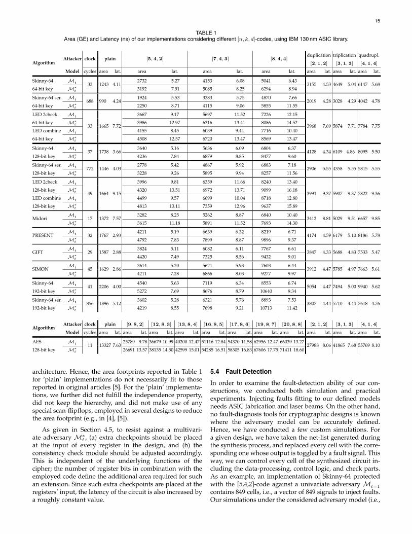
15
TABLE 1Area (GE) and Latency (ns) of our implementations considering different [n, k, d]-codes, using IBM 130 nm ASIC library.
AlgorithmAttacker clock plain [5, 4, 2] [7, 4, 3] [8, 4, 4]
duplication triplication quadrupl.
[2, 1, 2] [3, 1, 3] [4, 1, 4]
Model cycles area lat. area lat. area lat. area lat. area lat. area lat. area lat.
Skinny-64 Mt 33 1243 4.112732 5.27 4153 6.08 5041 6.43
3155 4.53 4649 5.04 6147 5.6864-bit key M∗
t 3192 7.91 5085 8.25 6294 8.94
Skinny-64 ser. Mt 688 990 4.241924 5.53 3383 5.75 4870 7.66
2019 4.28 3028 4.29 4042 4.7864-bit key M∗
t 2250 8.71 4115 9.06 5855 11.55
LED 2check Mt
33 1665 7.72
3667 9.17 5697 11.52 7226 12.15
3968 7.69 5874 7.71 7784 7.7564-bit key M∗
t 3986 12.97 6316 13.41 8086 14.52
LED combine Mt 4155 8.45 6039 9.44 7716 10.40
64-bit key M∗t 4508 12.57 6720 13.47 8569 13.47
Skinny-64 Mt 37 1738 3.663640 5.16 5636 6.09 6804 6.37
4128 4.34 6109 4.86 8095 5.50128-bit key M∗
t 4236 7.84 6879 8.85 8477 9.60
Skinny-64 ser. Mt 772 1446 4.032778 5.42 4867 5.92 6883 7.18
2906 5.55 4358 5.55 5815 5.55128-bit key M∗
t 3228 9.26 5895 9.94 8257 11.56
LED 2check Mt
49 1664 9.15
3996 9.81 6359 11.66 8240 13.40
3991 9.37 5907 9.37 7822 9.36128-bit key M∗
t 4320 13.51 6972 13.71 9099 16.18
LED combine Mt 4499 9.57 6699 10.04 8718 12.80
128-bit key M∗t 4813 13.11 7359 12.96 9637 15.89
MidoriMt 17 1372 7.57
3282 8.25 5262 8.87 6840 10.403412 8.81 5029 9.51 6657 9.85
M∗t 3615 11.18 5891 11.52 7693 14.30
PRESENTMt 32 1767 2.93
4211 5.19 6639 6.32 8219 6.714174 4.59 6179 5.10 8186 5.78
M∗t 4792 7.83 7899 8.87 9896 9.37
GIFTMt 29 1587 2.88
3824 5.11 6082 6.11 7767 6.613847 4.33 5688 4.83 7533 5.47
M∗t 4420 7.49 7325 8.56 9432 9.01
SIMONMt 45 1629 2.86
3614 5.20 5621 5.93 7603 6.443912 4.47 5785 4.97 7663 5.61
M∗t 4211 7.28 6866 8.03 9277 9.97
Skinny-64 Mt 41 2206 4.004540 5.63 7119 6.34 8553 6.74
5054 4.47 7494 5.00 9940 5.62192-bit key M∗
t 5272 7.69 8676 8.79 10640 9.34
Skinny-64 ser. Mt 856 1896 5.123602 5.28 6321 5.76 8893 7.53
3807 4.44 5710 4.44 7618 4.76192-bit key M∗
t 4219 8.55 7698 9.21 10713 11.42
AlgorithmAttacker clock plain [9, 8, 2] [12, 8, 3] [13, 8, 4] [16, 8, 5] [17, 8, 6] [19, 8, 7] [20, 8, 8] [2, 1, 2] [3, 1, 3] [4, 1, 4]
Model cycles area lat. area lat. area lat. area lat. area lat. area lat. area lat. area lat. area lat. area lat. area lat.
AES Mt 11 13327 7.6325789 9.78 36679 10.99 40200 12.47 51116 12.84 54370 11.58 62956 12.47 66039 13.27
27988 8.06 41865 7.68 55769 8.10128-bit key M∗
t 26691 13.57 38135 14.50 42599 15.01 54285 16.51 58305 16.83 67606 17.75 71411 18.60
architecture. Hence, the area footprints reported in Table 1for ‘plain’ implementations do not necessarily fit to thosereported in original articles [5]. For the ‘plain’ implementa-tions, we further did not fulfill the independence property,did not keep the hierarchy, and did not make use of anyspecial scan-flipflops, employed in several designs to reducethe area footprint (e.g., in [4], [5]).
As given in Section 4.5, to resist against a multivari-ate adversary M∗t , (a) extra checkpoints should be placedat the input of every register in the design, and (b) theconsistency check module should be adjusted accordingly.This is independent of the underlying functions of thecipher; the number of register bits in combination with theemployed code define the additional area required for suchan extension. Since such extra checkpoints are placed at theregisters’ input, the latency of the circuit is also increased bya roughly constant value.
5.4 Fault Detection
In order to examine the fault-detection ability of our con-structions, we conducted both simulation and practicalexperiments. Injecting faults fitting to our defined modelsneeds ASIC fabrication and laser beams. On the other hand,no fault-diagnosis tools for cryptographic designs is knownwhere the adversary model can be accurately defined.Hence, we have conducted a few custom simulations. Fora given design, we have taken the net-list generated duringthe synthesis process, and replaced every cell with the corre-sponding one whose output is toggled by a fault signal. Thisway, we can control every cell of the synthesized circuit in-cluding the data-processing, control logic, and check parts.As an example, an implementation of Skinny-64 protectedwith the [5,4,2]-code against a univariate adversary Mt=1
contains 849 cells, i.e., a vector of 849 signals to inject faults.Our simulations under the considered adversary model (i.e.,

16
single-bit faults at one clock cycle for every encryption)showed 100% fault coverage. We have repeated this processon our other implementations (with larger codes as wellas multivariate adversary model). In all cases, we havenot observed any undetected fault fitting into the boundedmodel.
For the practical experiments, we made use of a Basys 3toolkit board from Digilent equipped with an Artix-7FPGA [49]. We followed the principle expressed in [50] toinject faults by clock glitch, i.e., a signal generator providesan external clock signal with adjustable frequency which ismultiplied by a constant factor inside the FPGA by a DigitalClock Management (DCM) unit, and the ordinary clock isreplaced by the fast clock at selected clock cycles to injectclock glitch. For a given design we have started to decreasethe clock glitch duration to get faulty values. This way wehave no precise control over the number of injected faults,but by shortening the clock glitch we first violate the delayof the critical path of the circuit. For each clock glitch period,we gave the circuit 1000 random plaintexts (with a fixedkey), and extracted the ratios of fault-free, detected, andfaulty results. Figure 15 demonstrates such ratios over theduration of the clock glitch for different AES designs includ-ing unprotected, duplication/triplication/quadruplication,and the ones protected by our scheme using various codes.In all cases we evaluated the variants protected against theunivariate Mt model, and injected the clock glitch at thelast encryption round. The benefit of our constructions com-pared to the unprotected design is clearly shown, but com-pared to duplication/triplication/quadruplication it can beseen that there are some faults which pass through theduplication mechanisms (i.e., symmetric faults) which arefully avoided in our designs. Since the duplicated modulesA and A′ are implemented similarly, they have very similarcritical path; hence a clock glitch has some times equal effecton both/multiple instances. This does not happen in ourconstructions leading to 0 faulty ratio.
6 CONCLUSION
Fault attacks can be easily utilized to extract sensitive in-formation from any unprotected cryptographic implementa-tion. Therefore, the inclusion of a dedicated countermeasurein the design process is essential and sparked numerousresearch contributions covering different hardening tech-niques. However, we have shown that the actual realizationof these schemes in practice is not trivial. Many previouspublications have not considered the crucial threat of faultpropagation and, thus, provide only a reduced detectionpotential.
In this work, we have defined an adjustable adversarywhich takes advantages of this phenomenon and presenteddesign strategies to cope with this new constraint. Ourconcepts allow the robust implementation of CED schemesin the presence of fault propagation. We defined a univariate(resp. multivariate) adversary model, in which the attackerat one (resp. every) clock cycle is able to make up to t cellsfaulty in the entire circuit. Accordingly, we showed howto provide security (i.e., full fault coverage) against such apowerful adversary with high precision. Furthermore, weextended our observations to the often-neglected protection
46810Glitch duration [ns]
0
0.5
1
Rat
io fault-freedetectedfaulty
(a) unprotected
46810Glitch duration [ns]
0
0.5
1
Rat
io fault-freedetectedfaulty
(b) [2,1,2]-code (duplication)
46810Glitch duration [ns]
0
0.5
1
Rat
io fault-freedetectedfaulty
(c) [3,1,3]-code (triplication)
46810Glitch duration [ns]
0
0.5
1
Rat
io fault-freedetectedfaulty
(d) [4,1,4]-code (quadruplication)
46810Glitch duration [ns]
0
0.5
1
Rat
io fault-freedetectedfaulty
(e) [9,8,2]-code
46810Glitch duration [ns]
0
0.5
1
Rat
io fault-freedetectedfaulty
(f) [12,8,3]-code
46810Glitch duration [ns]
0
0.5
1
Rat
io fault-freedetectedfaulty
(g) [17,8,6]-code
46810Glitch duration [ns]
0
0.5
1
Rat
io fault-freedetectedfaulty
(h) [19,8,7]-code
Fig. 15. Result of fault injection by clock glitch on different implementa-tions of AES.
of control signals and presented solutions to achieve anentirely fault-resistant architecture.
Our case studies show the efficiency of our approach fordifferent symmetric block ciphers and highlight the effectof the chosen code on the resulting overhead. Overall, tothe best of our knowledge, we presented the first secureand efficient design methodology against a realistic t-cellbounded adversary in the presence of fault propagation. Wemade the HDL code of our entire designs publicly availablethrough https://github.com/emsec/ImpeccableCircuits.
Regarding future works, an ASIC-based practical evalu-ation of the fault-resistance of our designs using laser faultinjections could be of great interest. This would not only in-crease the confidence in our methodology, but also allows toobtain a realistic estimate for the number of possible faultycells t in practice. It is noteworthy that the fault detectionability of our constructions relies on the definition of theunderlying code. Hence, the fault coverage of every module

17
is straightforwardly obtained. However, there is an obviouslack of a simulation/verification tool to examine the faultcoverage of a given design considering a certain adversarymodel. The available logic simulation tools have not beendesigned for this purpose. The scientific community wouldfor sure benefit by having such a tool enabling verificationof the claimed fault coverages.
Another important aspect which needs to be furtherexamined is error correction. Recently, it has been demon-strated that combining a CED with state randomization(i.e., masking) does not provide sufficient protection againststatistical ineffective fault attacks (SIFA) [51]. One proposedcountermeasure is the inclusion of dummy rounds or otherhiding techniques which can be straight-forwardly com-bined with our methodology. In addition, however, extend-ing the encoded circuit with the capability to correct faultystates would raise the bar for an adversary to create theerrors even further. Therefore, a combination of differenttechniques might provide the best results, but this requiresfurther research especially regarding combined attacks.
REFERENCES
[1] D. Boneh, R. A. DeMillo, and R. J. Lipton, “On the Importanceof Checking Cryptographic Protocols for Faults (Extended Ab-stract),” in EUROCRYPT, ser. LNCS, vol. 1233. Springer, 1997,pp. 37–51.
[2] H. Bar-El, H. Choukri, D. Naccache, M. Tunstall, and C. Whelan,“The Sorcerer’s Apprentice Guide to Fault Attacks,” Proceedings ofthe IEEE, vol. 94, no. 2, pp. 370–382, 2006.
[3] X. Guo, D. Mukhopadhyay, C. Jin, and R. Karri, “Security analysisof concurrent error detection against differential fault analysis,” J.Cryptographic Eng., vol. 5, no. 3, pp. 153–169, 2015.
[4] A. Bogdanov, L. R. Knudsen, G. Leander, C. Paar, A. Poschmann,M. J. B. Robshaw, Y. Seurin, and C. Vikkelsoe, “PRESENT: AnUltra-Lightweight Block Cipher,” in CHES, ser. LNCS, vol. 4727.Springer, 2007, pp. 450–466.
[5] C. Beierle, J. Jean, S. Kolbl, G. Leander, A. Moradi, T. Peyrin,Y. Sasaki, P. Sasdrich, and S. M. Sim, “The SKINNY Family of BlockCiphers and Its Low-Latency Variant MANTIS,” in CRYPTO, ser.LNCS, vol. 9815. Springer, 2016, pp. 123–153.
[6] S. Banik, A. Bogdanov, T. Isobe, K. Shibutani, H. Hiwatari, T. Ak-ishita, and F. Regazzoni, “Midori: A Block Cipher for Low Energy,”in ASIACRYPT, ser. LNCS, vol. 9453. Springer, 2015, pp. 411–436.
[7] S. Banik, S. K. Pandey, T. Peyrin, Y. Sasaki, S. M. Sim, andY. Todo, “GIFT: A Small Present - Towards Reaching the Limitof Lightweight Encryption,” in CHES, ser. LNCS, vol. 10529.Springer, 2017, pp. 321–345.
[8] J. Guo, T. Peyrin, A. Poschmann, and M. J. B. Robshaw, “The LEDBlock Cipher,” in CHES, ser. LNCS, vol. 6917. Springer, 2011, pp.326–341.
[9] R. Beaulieu, D. Shors, J. Smith, S. Treatman-Clark, B. Weeks, andL. Wingers, “The SIMON and SPECK lightweight block ciphers,”in DAC. ACM, 2015, pp. 175:1–175:6.
[10] J. Daemen and V. Rijmen, The Design of Rijndael: AES - The AdvancedEncryption Standard, ser. Information Security and Cryptography.Springer, 2002.
[11] V. Ocheretnij, G. Kouznetsov, R. Karri, and M. Gossel, “On-LineError Detection and BIST for the AES Encryption Algorithm withDifferent S-Box Implementations,” in IOLTS, 2005, pp. 141–146.
[12] S. Azzi, B. Barras, M. Christofi, and D. Vigilant, “Using linearcodes as a fault countermeasure for nonlinear operations: applica-tion to AES and formal verification,” J. Cryptographic Engineering,vol. 7, no. 1, pp. 75–85, 2017.
[13] T. Schneider, A. Moradi, and T. Guneysu, “ParTI - TowardsCombined Hardware Countermeasures Against Side-Channeland Fault-Injection Attacks,” in CRYPTO, ser. LNCS, vol. 9815.Springer, 2016, pp. 302–332.
[14] S. Nikova, V. Rijmen, and M. Schlaffer, “Secure Hardware Imple-mentation of Nonlinear Functions in the Presence of Glitches,” J.Cryptology, vol. 24, no. 2, pp. 292–321, 2011.
[15] Y. Ishai, M. Prabhakaran, A. Sahai, and D. Wagner, “Private Cir-cuits II: Keeping Secrets in Tamperable Circuits,” in EUROCRYPT,ser. LNCS, vol. 4004, 2006, pp. 308–327.
[16] T. D. Cnudde and S. Nikova, “More Efficient Private Circuits IIthrough Threshold Implementations,” in FDTC. IEEE ComputerSociety, 2016, pp. 114–124.
[17] O. Seker, A. Fernandez-Rubio, T. Eisenbarth, and R. Steinwandt,“Extending glitch-free multiparty protocols to resist fault injectionattacks,” IACR Trans. Cryptogr. Hardw. Embed. Syst., vol. 2018, no. 3,pp. 394–430, 2018.
[18] O. Reparaz, L. De Meyer, B. Bilgin, V. Arribas, S. Nikova, V. Nikov,and N. P. Smart, “CAPA: the spirit of beaver against physicalattacks,” in CRYPTO 2018, ser. LNCS, vol. 10991. Springer, 2018,pp. 121–151.
[19] B. Yuce, N. F. Ghalaty, and P. Schaumont, “TVVF: Estimating thevulnerability of hardware cryptosystems against timing violationattacks,” in HOST. IEEE, 2015, pp. 72–77.
[20] N. Selmane, S. Guilley, and J. Danger, “Practical Setup TimeViolation Attacks on AES,” in EDCC-7, 2008, pp. 91–96.
[21] M. Agoyan, J. Dutertre, D. Naccache, B. Robisson, and A. Tria,“When Clocks Fail: On Critical Paths and Clock Faults,” inCARDIS, ser. LNCS, vol. 6035, 2010, pp. 182–193.
[22] J.-J. Quisquater and D. Samyde, “Eddy current for magnetic anal-ysis with active sensor,” in Proceedings of Esmart, 2002.
[23] S. P. Skorobogatov and R. J. Anderson, “Optical Fault InductionAttacks,” in CHES, ser. LNCS, vol. 2523. Springer, 2002, pp. 2–12.
[24] B. Selmke, J. Heyszl, and G. Sigl, “Attack on a DFA ProtectedAES by Simultaneous Laser Fault Injections,” in FDTC. IEEEComputer Society, 2016, pp. 36–46.
[25] R. B. Carpi, S. Picek, L. Batina, F. Menarini, D. Jakobovic, andM. Golub, “Glitch It If You Can: Parameter Search Strategiesfor Successful Fault Injection,” in CARDIS, ser. LNCS, vol. 8419.Springer, 2013, pp. 236–252.
[26] F. Schellenberg, M. Finkeldey, B. Richter, M. Schapers, N. Gerhardt,M. Hofmann, and C. Paar, “On the Complexity Reduction of LaserFault Injection Campaigns Using OBIC Measurements,” in FDTC.IEEE Computer Society, 2015, pp. 14–27.
[27] N. F. Ghalaty, B. Yuce, M. M. I. Taha, and P. Schaumont, “Differen-tial Fault Intensity Analysis,” in FDTC. IEEE Computer Society,2014, pp. 49–58.
[28] T. Fuhr, E. Jaulmes, V. Lomne, and A. Thillard, “Fault Attacks onAES with Faulty Ciphertexts Only,” in FDTC. IEEE ComputerSociety, 2013, pp. 108–118.
[29] E. Biham and A. Shamir, “Differential Fault Analysis of Secret KeyCryptosystems,” in CRYPTO, ser. LNCS, vol. 1294. Springer, 1997,pp. 513–525.
[30] A. Moradi, O. Mischke, C. Paar, Y. Li, K. Ohta, and K. Sakiyama,“On the Power of Fault Sensitivity Analysis and Collision Side-Channel Attacks in a Combined Setting,” in CHES, ser. LNCS, vol.6917. Springer, 2011, pp. 292–311.
[31] C. Dobraunig, M. Eichlseder, T. Korak, S. Mangard, F. Mendel,and R. Primas, “SIFA: exploiting ineffective fault inductions onsymmetric cryptography,” IACR Trans. Cryptogr. Hardw. Embed.Syst., vol. 2018, no. 3, pp. 547–572, 2018.
[32] G. Bertoni, L. Breveglieri, I. Koren, P. Maistri, and V. Piuri, “ErrorAnalysis and Detection Procedures for a Hardware Implementa-tion of the Advanced Encryption Standard,” IEEE Trans. Comput-ers, vol. 52, no. 4, pp. 492–505, 2003.
[33] C. Ananiadis, A. Papadimitriou, D. Hely, V. Beroulle, P. Maistri,and R. Leveugle, “On the development of a new countermeasurebased on a laser attack RTL fault model,” in DATE. IEEE, 2016,pp. 445–450.
[34] C. Yen and B. Wu, “Simple Error Detection Methods for HardwareImplementation of Advanced Encryption Standard,” IEEE Trans.Computers, vol. 55, no. 6, pp. 720–731, 2006.
[35] F. J. MacWilliams and N. J. A. Sloane, The theory of error correctingcodes, ser. North-Holland mathematical library. North-HollandPub. Co. New York, 1977.
[36] T. Malkin, F. Standaert, and M. Yung, “A ComparativeCost/Security Analysis of Fault Attack Countermeasures,” inFDTC, ser. LNCS, vol. 4236. Springer, 2006, pp. 159–172.
[37] R. Karri, K. Wu, P. Mishra, and Y. Kim, “Concurrent error detectionschemes for fault-based side-channel cryptanalysis of symmetricblock ciphers,” IEEE Trans. on CAD of Integrated Circuits andSystems, vol. 21, no. 12, pp. 1509–1517, 2002.
[38] K. D. Akdemir, Z. Wang, M. G. Karpovsky, and B. Sunar, “Designof Cryptographic Devices Resilient to Fault Injection Attacks Us-

18
ing Nonlinear Robust Codes,” in Fault Analysis in Cryptography.Springer, 2012, pp. 171–199.
[39] K. J. Kulikowski, Z. Wang, and M. G. Karpovsky, “ComparativeAnalysis of Robust Fault Attack Resistant Architectures for Publicand Private Cryptosystems,” in FDTC. IEEE Computer Society,2008, pp. 41–50.
[40] S. Patranabis, A. Chakraborty, P. H. Nguyen, and D. Mukhopad-hyay, “A Biased Fault Attack on the Time Redundancy Counter-measure for AES,” in COSADE, ser. LNCS, vol. 9064. Springer,2015, pp. 189–203.
[41] S. Guilley, L. Sauvage, J. Danger, N. Selmane, and R. Pacalet,“Silicon-level Solutions to Counteract Passive and Active At-tacks,” in FDTC. IEEE, 2008, pp. 3–17.
[42] M. Agoyan, J. Dutertre, A. Mirbaha, D. Naccache, A. Ribotta, andA. Tria, “How to flip a bit?” in IOLTS. IEEE Computer Society,2010, pp. 235–239.
[43] F. Courbon, P. Loubet-Moundi, J. J. A. Fournier, and A. Tria, “Ad-justing Laser Injections for Fully Controlled Faults,” in COSADE,ser. LNCS, vol. 8622, 2014, pp. 229–242.
[44] A. Satoh, T. Sugawara, N. Homma, and T. Aoki, “High-Performance Concurrent Error Detection Scheme for AES Hard-ware,” in CHES 2008, ser. LNCS, vol. 5154. Springer, 2008, pp.100–112.
[45] A. Moradi, M. T. M. Shalmani, and M. Salmasizadeh, “A General-ized Method of Differential Fault Attack Against AES Cryptosys-tem,” in CHES 2006, ser. LNCS, vol. 4249. Springer, 2006, pp.91–100.
[46] O. Reparaz, B. Bilgin, S. Nikova, B. Gierlichs, and I. Verbauwhede,“Consolidating Masking Schemes,” in CRYPTO 2015, ser. LNCS,vol. 9215. Springer, 2015, pp. 764–783.
[47] H. Groß, S. Mangard, and T. Korak, “An Efficient Side-ChannelProtected AES Implementation with Arbitrary Protection Order,”in CT-RSA 2017, ser. LNCS, vol. 10159. Springer, 2017, pp. 95–112.
[48] J. Jean, A. Moradi, T. Peyrin, and P. Sasdrich, “Bit-Sliding: AGeneric Technique for Bit-Serial Implementations of SPN-basedPrimitives - Applications to AES, PRESENT and SKINNY,” inCHES, ser. LNCS, vol. 10529. Springer, 2017, pp. 687–707.
[49] Digilent, “Basys3,” 2019, https://reference.digilentinc.com/reference/programmable-logic/basys-3/.
[50] A. Moradi, O. Mischke, and C. Paar, “One Attack to Rule ThemAll: Collision Timing Attack versus 42 AES ASIC Cores,” IEEETrans. Computers, vol. 62, no. 9, pp. 1786–1798, 2013.
[51] C. Dobraunig, M. Eichlseder, H. Groß, S. Mangard, F. Mendel, andR. Primas, “Statistical Ineffective Fault Attacks on Masked AESwith Fault Countermeasures,” in ASIACRYPT 2018, ser. LNCS, vol.11273. Springer, 2018, pp. 315–342.

19
APPENDIX
rst
S
MC
RC(FSM)
RK
Ciphertext ×4
0 1 2 3
SR SR SR SRMC
MC0
MC0
C C C C
4 5 6 7
SR SR SR SRMC
MC1
MC1
C C C C
8 9 10 11
SR SR SR SRMC
MC2
MC2
C C C C
12 13 14 15SR MC
MC3
rst
MC3
Plaintext
×4C C C C
rst
F◦S◦F−1
F◦MC◦F−1
RC ′(FSM ′)
RK ′
0 1 2 3
SR′ SR′ SR′ SR′MC′
MC ′0
MC ′0
C ′ C ′ C ′ C ′
4 5 6 7
SR′ SR′ SR′ SR′MC′
MC ′1
MC ′1
C ′ C ′ C ′ C ′
8 9 10 11
SR′ SR′ SR′ SR′MC′
MC ′2
MC ′2
C ′ C ′ C ′ C ′
12 13 14 15SR′ MC′
MC ′3
rst
MC ′3
Plaintext′C ′ C ′ C ′ C ′
F
×k
×m ≥ k
Fig. 16. Skinny, nibble-serial, data path, m ≥ k.

20
LFSR
RK ×40 1 2 3
en enP
enP
enP
C C C C
4 5 6 7
enP
en enP
enP rst
C C C C
8 9 10 11
en en en enC C C C
12 13 14 15
en en enen
rstKey
×4C C C C
F◦LFSR◦F−1
0 1 2 3
en′ en′P′
en′P′
en′P′
C ′ C ′ C ′ C ′
4 5 6 7
en′P′
en′ en′P′
en′P′ rst
C ′ C ′ C ′ C ′
8 9 10 11
en′ en′ en′ en′C ′ C ′ C ′ C ′
12 13 14 15
en′ en′ en′en′
rstKey′C ′ C ′ C ′ C ′
F
×k
×m ≥ k
Fig. 17. Skinny, nibble-serial, key path, m ≥ k.

21
rst
S
MC
RC(FSM)
RK
Ciphertext ×4
0 1 2 3
SR SR SR SRMC
MC0
MC0
C C C C
4 5 6 7
SR SR SR SRMC
MC1
MC1
C C C C
8 9 10 11
SR SR SR SRMC
MC2
MC2
C C C C
12 13 14 15SR MC
MC3
rst
MC3
Plaintext
×4C C C C
rst
F◦S
F◦MC
RC ′(FSM ′)
RK ′
0 1 2 3
SR′ SR′ SR′ SR′MC′
MC ′0
MC ′0
C ′ C ′ C ′ C ′
4 5 6 7
SR′ SR′ SR′ SR′MC′
MC ′1
MC ′1
C ′ C ′ C ′ C ′
8 9 10 11
SR′ SR′ SR′ SR′MC′
MC ′2
MC ′2
C ′ C ′ C ′ C ′
12 13 14 15SR′ MC′
MC ′3
rst
MC ′3
Plaintext′C ′ C ′ C ′ C ′
F
×k
×m < k
Fig. 18. Skinny, nibble-serial, data path, m < k.

22
LFSR
RK ×40 1 2 3
en enP
enP
enP
C C C C
4 5 6 7
enP
en enP
enP rst
C C C C
8 9 10 11
en en en enC C C C
12 13 14 15
en en enen
rstKey
×4C C C C
F◦LFSR
0 1 2 3
en′ en′P′
en′P′
en′P′
C ′ C ′ C ′ C ′
4 5 6 7
en′P′
en′ en′P′
en′P′ rst
C ′ C ′ C ′ C ′
8 9 10 11
en′ en′ en′ en′C ′ C ′ C ′ C ′
12 13 14 15
en′ en′ en′en′
rstKey′C ′ C ′ C ′ C ′
F
×k
×m < k
Fig. 19. Skinny, nibble-serial, key path, m < k.
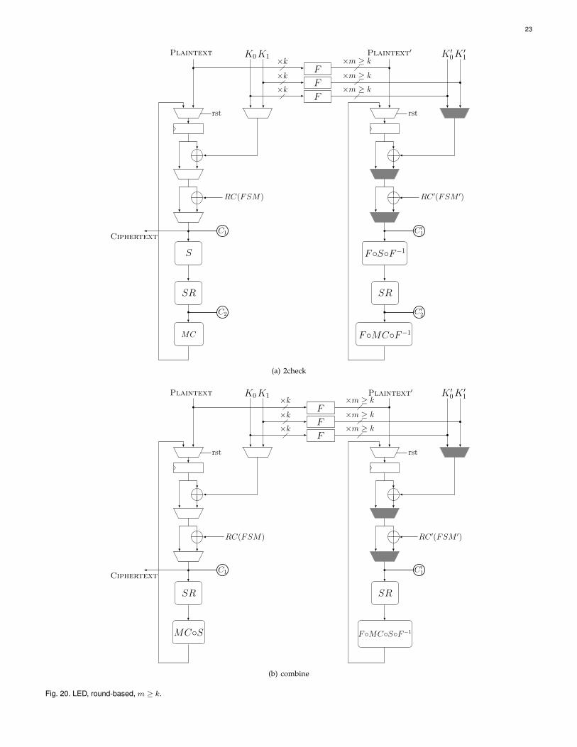
23
rst
SR
S
Plaintext K1K0
F
F
F
Ciphertext
MC
C1
C2
RC(FSM)
rst
SR
F◦S◦F−1
Plaintext′ K ′1K ′0
F◦MC◦F−1
C ′1
C ′2
RC ′(FSM ′)
×k×k×k
×m ≥ k
×m ≥ k
×m ≥ k
(a) 2check
rst
SR
Plaintext K1K0
F
F
F
Ciphertext
MC◦S
C1
RC(FSM)
rst
SR
Plaintext′ K ′1K ′0
F◦MC◦S◦F−1
C ′1
RC ′(FSM ′)
×k×k×k
×m ≥ k
×m ≥ k
×m ≥ k
(b) combine
Fig. 20. LED, round-based, m ≥ k.
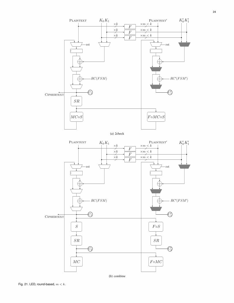
24
rst
SR
Plaintext K1K0
F
F
F
Ciphertext
MC◦S
C1
RC(FSM)
rst
Plaintext′ K ′1K ′0
F◦MC◦S
C ′1
RC ′(FSM ′)
×k×k×k
×m < k
×m < k
×m < k
(a) 2check
rst
SR
S
Plaintext K1K0
F
F
F
Ciphertext
MC
C1
C2
RC(FSM)
rst
SR
F◦S
Plaintext′ K ′1K ′0
F◦MC
C ′1
C ′2
RC ′(FSM ′)
×k×k×k
×m < k
×m < k
×m < k
(b) combine
Fig. 21. LED, round-based, m < k.

25
rst
S
SR
Plaintext K1K0
F
F
F
Ciphertext
MC
C1
RC(FSM)
rst
F◦S◦F−1
Plaintext′ K ′1K ′0
MC
SR
C ′1
RC ′(FSM ′)
×k×k×k
×m ≥ k
×m ≥ k
×m ≥ k
Fig. 22. Midori, round-based, m ≥ k.
rst
S
SR
Plaintext K1K0
F
F
F
Ciphertext
MC
C1
RC(FSM)
rst
F◦S
Plaintext′ K ′1K ′0
MC
SR
C ′1
RC ′(FSM ′)
×k×k×k
×m < k
×m < k
×m < k
Fig. 23. Midori, round-based, m < k.

26
rst rst
S P
Plaintext Key
F
F
Ciphertext
FSM
PS S
C1 C2
part
rst rst
Plaintext′ Key′
FSM′
F◦P◦S◦F−1F◦S◦F−1F◦S◦F−1 F◦P◦F−1
C ′1 C ′2
part
×k
×k
×m ≥ k
×m ≥ k
Fig. 24. PRESENT, round-based, m ≥ k.
rst rst
SP
Plaintext Key
F
F
Ciphertext
FSM
PS S
C1 C2
part
rst rst
Plaintext′ Key′
FSM′
F◦P◦SF◦S F◦S F◦P
C ′1 C ′
2
part
×k
×k
×m < k
×m < k
Fig. 25. PRESENT, round-based, m < k.

27
rst rst
SP
Plaintext Key
F
F
Ciphertext
P
C1 C2
part
rst rst
F◦P◦S◦F−1 F◦P◦F−1
Plaintext′ Key′
C ′1 C ′2
part
k
k
×m ≥ k
×m ≥ k
Fig. 26. GIFT, round-based, m ≥ k.
rst rst
SP
Plaintext Key
F
F
Ciphertext
P
C1 C2
part
rst rst
F◦P◦S F◦P
Plaintext′ Key′
C ′1 C ′
2
part
×k
×k
×m < k
×m < k
Fig. 27. GIFT, round-based, m < k.

28
rst rst
F◦f◦F−1F◦f◦F−1
Plaintext′ Key′
Const′(FSM′)
C ′1 C ′2
rst rst
f f
Plaintext Key
F
F
Ciphertext
Const(FSM)
C1 C2
×k
×k
×m ≥ k
×m ≥ k
Fig. 28. SIMON, round-based, m ≥ k.
rst rst
F◦f F◦f
Plaintext′ Key′
Const′(FSM′)
C ′1 C ′
2
rst rst
ff
Plaintext Key
F
F
Ciphertext
Const(FSM)
C1 C2
×k
×k
×m < k
×m < k
Fig. 29. SIMON, round-based, m < k.