09/27469 - artc - extranet - engineering · 09/27469. safety on track during work: ... 7 safety on...
TRANSCRIPT


safety on track during work: temporary fences
SMARTFENCE
Introduction + User instruction
2
safety on track during work: temporary fences
Content
• SMARTFENCE RAIL
– INTRODUCTION• goal and how• requirements• components• configuration
– INSTALLATION• Points to start with• Preparation• Installation - a• Installation - b• Installation - c
• SMARTFENCE METRO - short intro
2

3
safety on track during work: temporary fences
Introduction
• Goal: separate people from danger during work on railway track.
– European standard SAFETY ON TRACK DURING WORK: temporary fences
• How?
– Rimini principle: if costs > % contract, lower safety measurement• Halting train services• Physical Barriers• AWS • Personal protective equipment
3
4
safety on track during work: temporary fences
Introduction
• Requirements:
– Technical: according to EN standard• measurements• static and dynamic loads• electrical behaviour / infracompatability
– Ergonomic:• easy installation• minimum weight
– Commercial:• quick installation and dismantling• competitive price (TCO)
4
5
safety on track during work: temporary fences
INTRODUCTION
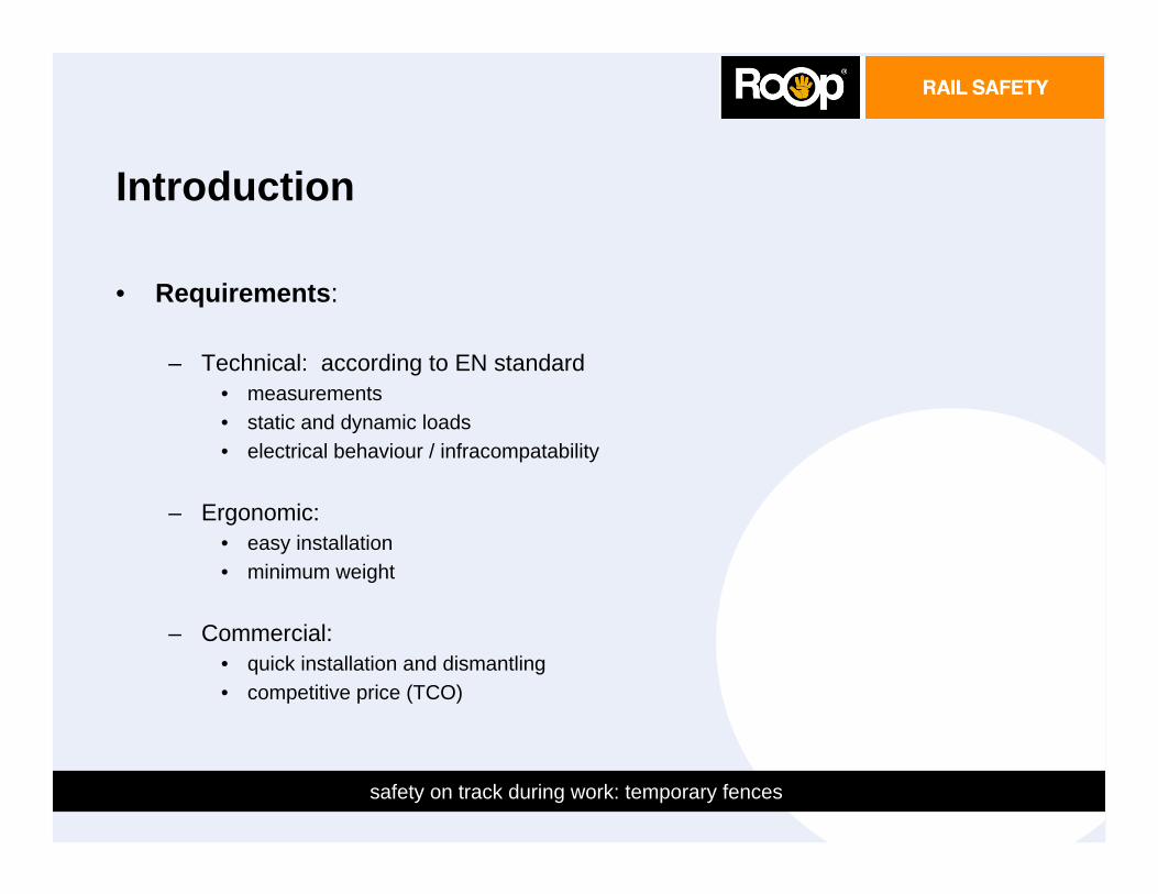
• COMPONENTS:
– Clamp (patented):• can be used on:
– different sleepers (concrete / timber / ... )– different fasteners ( vossloh / pandrol / ..... )– different rail sizes (UIC60 / UIC54 / S48 / NP46 / 68 / .... )– optional clamp extension part to increase distance from center track to fence.
– Post:• Adjustable distance to centre track• Adapter for distances over 2,1 m1 from edge of track• Fastclips to hold fence
– Fence:• any colour available• quick installation
5

6
safety on track during work: temporary fences
INTRODUCTION
• CONFIGURATION
6
7
safety on track during work: temporary fences
SMARTFENCE RAIL SYSTEM
• INSTALLATION: Points to start with
Study the risk analysis;
The minimum length of 1 Smartfence section is 6 m1.
There is no maximum length of a system.
The Smartfence system can be used from a radius of 150 m1, without restrictions.
You are using the clamp for a 68 kg rail. If installed on other size of rail, the front part of the clamp has to be replaced by the front part for this size.
7
8
safety on track during work: temporary fences
SMARTFENCE RAIL SYSTEM
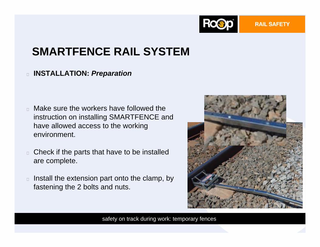
INSTALLATION: Preparation
Make sure the workers have followed the instruction on installing SMARTFENCE and have allowed access to the working environment.
Check if the parts that have to be installed are complete.
Install the extension part onto the clamp, by fastening the 2 bolts and nuts.
8
9
safety on track during work: temporary fences
SMARTFENCE RAIL SYSTEM
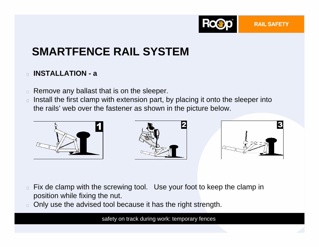
INSTALLATION - a
Remove any ballast that is on the sleeper.Install the first clamp with extension part, by placing it onto the sleeper into the rails’ web over the fastener as shown in the picture below.
Fix de clamp with the screwing tool. Use your foot to keep the clamp in position while fixing the nut.Only use the advised tool because it has the right strength.
9
10
safety on track during work: temporary fences
SMARTFENCE RAIL SYSTEM
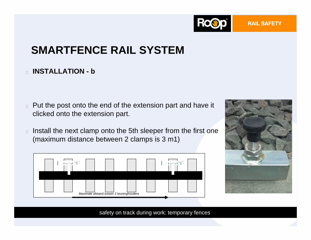
INSTALLATION - b
Put the post onto the end of the extension part and have it clicked onto the extension part.
Install the next clamp onto the 5th sleeper from the first one (maximum distance between 2 clamps is 3 m1)
10
Maximale afstand tussen 2 leuninghouders
11
safety on track during work: temporary fences
SMARTFENCE RAIL SYSTEM
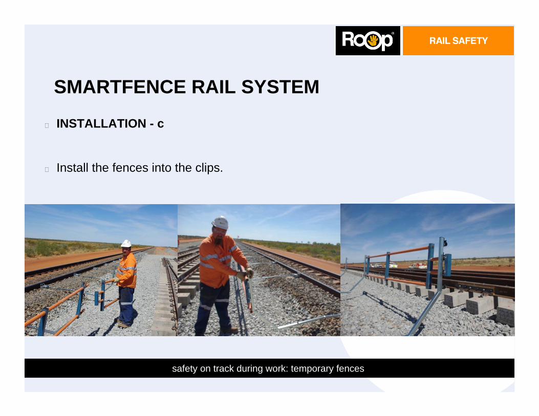
INSTALLATION - c
Install the fences into the clips.
11
12
safety on track during work: temporary fences
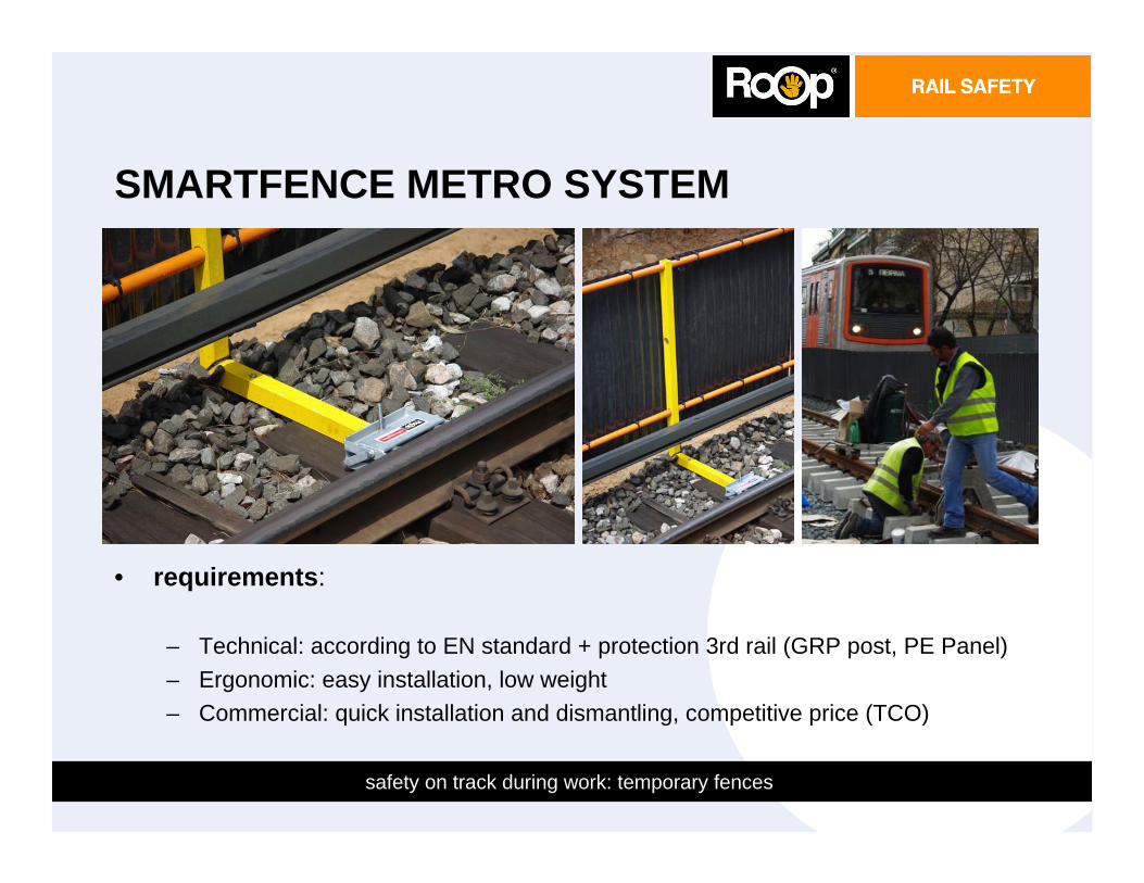
SMARTFENCE METRO SYSTEM
• requirements:
– Technical: according to EN standard + protection 3rd rail (GRP post, PE Panel) – Ergonomic: easy installation, low weight– Commercial: quick installation and dismantling, competitive price (TCO)
12
13
safety on track during work: temporary fences
SMARTFENCE
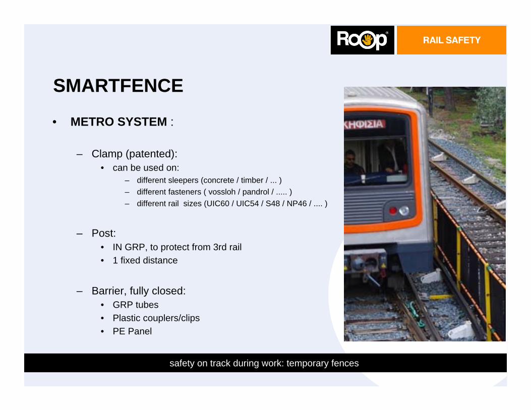
• METRO SYSTEM :
– Clamp (patented):• can be used on:
– different sleepers (concrete / timber / ... )– different fasteners ( vossloh / pandrol / ..... )– different rail sizes (UIC60 / UIC54 / S48 / NP46 / .... )
– Post:• IN GRP, to protect from 3rd rail• 1 fixed distance
– Barrier, fully closed:• GRP tubes• Plastic couplers/clips• PE Panel
13
safety on track during work: temporary fences
For more information:
Australia IMTRAM PTY LTD Mrs. Sonia Whiteman +613 9879 5200 www.imtram.com
Germany CONDOR gruppe Mr. Peter Zalewski +49 201 84153 113 www.condor-sicherheit.deGreece Ontrack RSE Mr. Yiannis Zartaloodes +30 210 6424995 www.ontrack-rse.gr
U.K. ETS Ltd Mr. Staniford +44 1925 425933 www.ets-uk.eu
Roop Rail Safety BVIndustrieweg 12
5627 BS EINDHOVENNetherlands
T. + 31 40 2901150F. +31 40 2901151
E. [email protected]. www.roopgroup.nl
Roop Rail Safety B.V. Industrieweg 12, 5627 BS Eindhoven NL • Tel. +31 (0)40 2901150 • Fax +31 (0)40 2901151 • K.v.k. 17237885 • BTW NL820189935B01Rabobank 172946743 • IBAN NL24RABO0172946743 • BIC RABONL2U • [email protected] • www.roopgroup.nl
Data Sheet
System ROOP FENCE RAIL (RFR) Types Suitable for DatasheetParts RFR001 Rail Clamp RFR001.001 UIC54
RFR001.002 UIC60RFR001.003 NP46RFR001.004 AUS 68kgRFR001.005 AUS 60kg
RFR001RFR002 Rail Post RFR002
RFR003 Rail Fence RFR003
RFR004 Clamp Extension RFR004
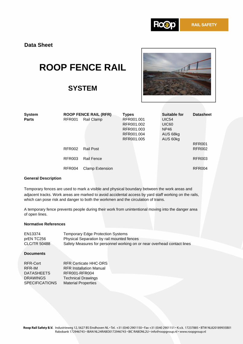
General Description
Temporary fences are used to mark a visible and physical boundary between the work areas and adjacent tracks. Work areas are marked to avoid accidental access by yard staff working on the rails,which can pose risk and danger to both the workmen and the circulation of trains.
A temporary fence prevents people during their work from unintentional moving into the danger areaof open lines.
Normative References
EN13374 Temporary Edge Protection SystemsprEN TC256 Physical Separation by rail mounted fencesCLC/TR 50488 Safety Measures for personnel working on or near overhead contact lines
Documents
RFR-Cert RFR Certicate HHC-DRSRFR-IM RFR Installation ManualDATASHEETS RFR001-RFR004DRAWINGS Technical Drawings SPECIFICATIONS Material Properties
ROOP FENCE RAIL
SYSTEM
Roop Rail Safety B.V. Industrieweg 12, 5627 BS Eindhoven NL • Tel. +31 (0)40 2901150 • Fax +31 (0)40 2901151 • K.v.k. 17237885 • BTW NL820189935B01Rabobank 172946743 • IBAN NL24RABO0172946743 • BIC RABONL2U • [email protected] • www.roopgroup.nl
Data Sheet
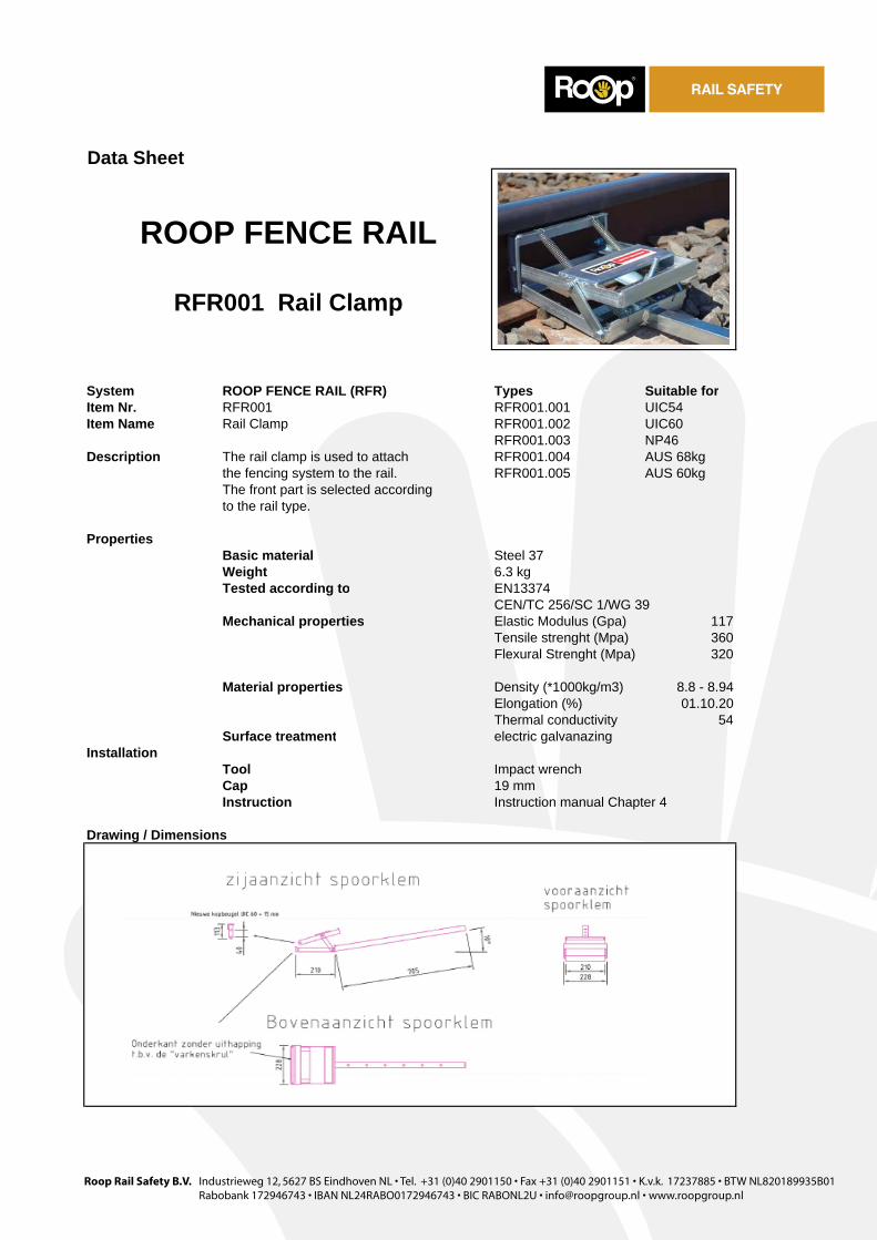
System ROOP FENCE RAIL (RFR) Types Suitable forItem Nr. RFR001 RFR001.001 UIC54Item Name Rail Clamp RFR001.002 UIC60
RFR001.003 NP46Description The rail clamp is used to attach RFR001.004 AUS 68kg
the fencing system to the rail. RFR001.005 AUS 60kgThe front part is selected accordingto the rail type.
PropertiesBasic material Steel 37Weight 6.3 kgTested according to EN13374
CEN/TC 256/SC 1/WG 39Mechanical properties Elastic Modulus (Gpa) 117
Tensile strenght (Mpa) 360Flexural Strenght (Mpa) 320
Material properties Density (*1000kg/m3) 8.8 - 8.94Elongation (%) 01.10.20Thermal conductivity 54
Surface treatmentInstallation
ToolCap 19 mmInstruction Instruction manual Chapter 4
Drawing / Dimensions
ROOP FENCE RAIL
RFR001 Rail Clamp
electric galvanazing
Impact wrench
Roop Rail Safety B.V. Industrieweg 12, 5627 BS Eindhoven NL • Tel. +31 (0)40 2901150 • Fax +31 (0)40 2901151 • K.v.k. 17237885 • BTW NL820189935B01Rabobank 172946743 • IBAN NL24RABO0172946743 • BIC RABONL2U • [email protected] • www.roopgroup.nl
Data Sheet
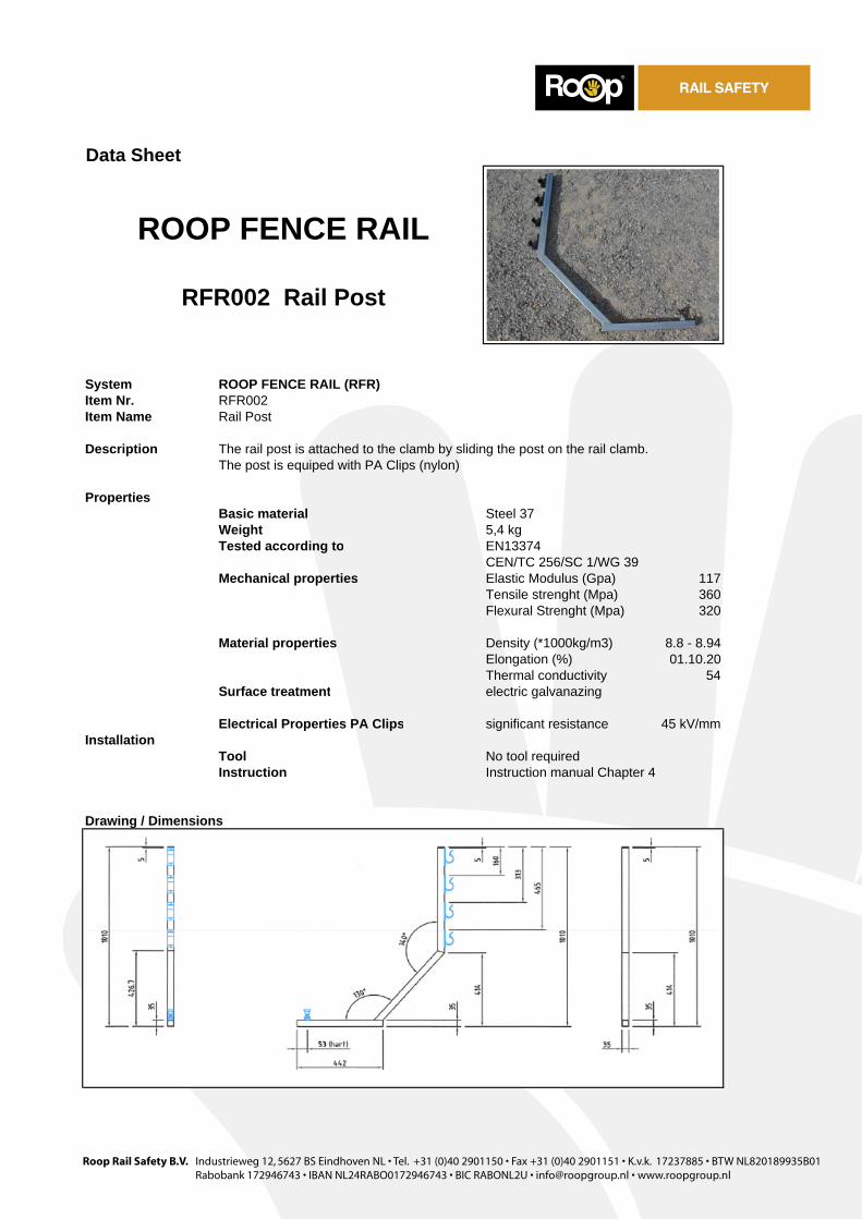
System ROOP FENCE RAIL (RFR)Item Nr. RFR002Item Name Rail Post
Description The rail post is attached to the clamb by sliding the post on the rail clamb.The post is equiped with PA Clips (nylon)
PropertiesBasic material Steel 37Weight 5,4 kgTested according to EN13374
CEN/TC 256/SC 1/WG 39Mechanical properties Elastic Modulus (Gpa) 117
Tensile strenght (Mpa) 360Flexural Strenght (Mpa) 320
Material properties Density (*1000kg/m3) 8.8 - 8.94Elongation (%) 01.10.20Thermal conductivity 54
Surface treatment
Electrical Properties PA Clips significant resistance 45 kV/mmInstallation
ToolInstruction Instruction manual Chapter 4
Drawing / Dimensions
ROOP FENCE RAIL
RFR002 Rail Post
electric galvanazing
No tool required
Roop Rail Safety B.V. Industrieweg 12, 5627 BS Eindhoven NL • Tel. +31 (0)40 2901150 • Fax +31 (0)40 2901151 • K.v.k. 17237885 • BTW NL820189935B01Rabobank 172946743 • IBAN NL24RABO0172946743 • BIC RABONL2U • [email protected] • www.roopgroup.nl
Data Sheet
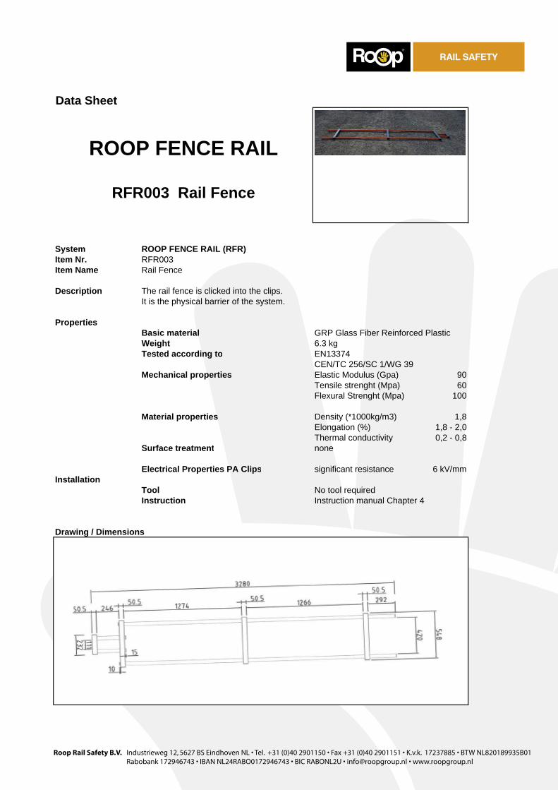
System ROOP FENCE RAIL (RFR)Item Nr. RFR003Item Name Rail Fence
Description The rail fence is clicked into the clips.It is the physical barrier of the system.
PropertiesBasic material GRP Glass Fiber Reinforced PlasticWeight 6.3 kgTested according to EN13374
CEN/TC 256/SC 1/WG 39Mechanical properties Elastic Modulus (Gpa) 90
Tensile strenght (Mpa) 60Flexural Strenght (Mpa) 100
Material properties Density (*1000kg/m3) 1,8Elongation (%) 1,8 - 2,0Thermal conductivity 0,2 - 0,8
Surface treatment
Electrical Properties PA Clips significant resistance 6 kV/mmInstallation
ToolInstruction Instruction manual Chapter 4
Drawing / Dimensions
ROOP FENCE RAIL
RFR003 Rail Fence
none
No tool required

Roop Rail Safety B.V. Industrieweg 12, 5627 BS Eindhoven NL • Tel. +31 (0)40 2901150 • Fax +31 (0)40 2901151 • K.v.k. 17237885 • BTW NL820189935B01Rabobank 172946743 • IBAN NL24RABO0172946743 • BIC RABONL2U • [email protected] • www.roopgroup.nl
Data Sheet
System ROOP FENCE RAIL (RFR)Item Nr. RFR004Item Name Clamp Extension
Description For distances 2,3 m1 <> 3 m1 from centre track, this extension part is used. It is attached to the clamp by 2 M10 Bolts / nuts.
PropertiesBasic material Steel 37Weight 5,4 kgTested according to EN13374
CEN/TC 256/SC 1/WG 39Mechanical properties Elastic Modulus (Gpa) 117
Tensile strenght (Mpa) 360Flexural Strenght (Mpa) 320
Material properties Density (*1000kg/m3) 8.8 - 8.94Elongation (%) 01.10.20Thermal conductivity 54
Surface treatment
InstallationToolInstruction Instruction manual Chapter 4
Drawing / Dimensions
ROOP FENCE RAIL
RFR004 Clamp Extension
electric galvanazing
No tool required

Documentnaam: Gebruikers Handleiding Versie: GHA2007-009 1
USER INSTRUCTION
PHYSICAL BARRIER, CHAPTER 4.

Documentnaam: Gebruikers Handleiding Versie: GHA2007-009 2
Inhoud 4. Installation 3
Documentnaam: Gebruikers Handleiding Versie: GHA2007-009 3
4 Installation Points to start with:
• Study the risk analysis; • The minimum lenght of 1 Smartfence system is 1 Barrier, with tho clamps and
posts. • There is no maximum lenghts of a system. • The Smartfence system can be used from a adius of 150 m1, without restrictions. • Make sure the proper clamp is selected. (C1.01A for UIC54, C1.01B for NP46,
C1.01C for UIC60). The type of clamp has tob e selected during preparation phase.
• Determine the right distance of the physical barrier from centre track, and make sure the workers know on which distance the system must be installed.
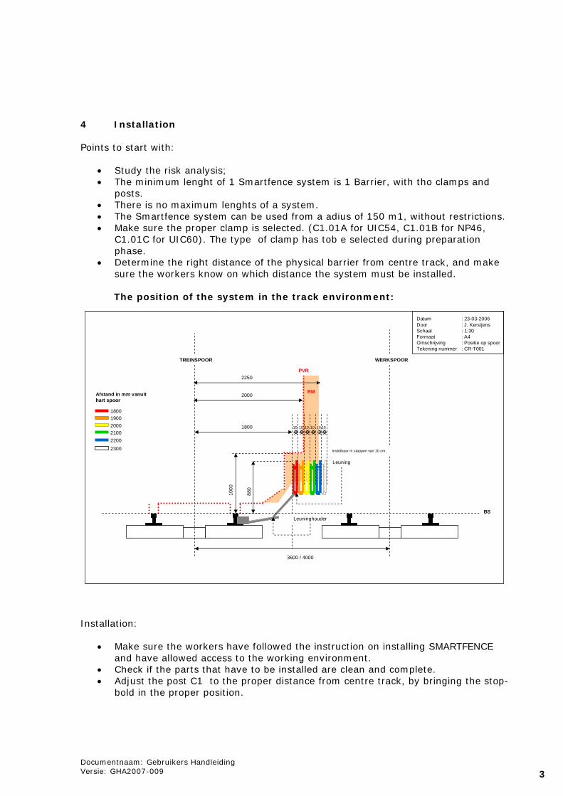
The position of the system in the track environment:
Datum : 23-03-2006Door : J. KerstjensSchaal : 1:30Formaat : A4Omschrijving : Positie op spoorTekening nummer : CR-T001
3600 / 4000
880
1800 10
TREINSPOOR WERKSPOOR
PVR
Leuning
Leuninghouder
Instelbaar in stappen van 10 cm.
Documentnaam: Product gegevensVersie: PRG2005-003
10 10 10 10 10
BS
2000
1000
2250
RM
18001900200021002200
2300
Afstand in mm vanuit hart spoor
Installation:
• Make sure the workers have followed the instruction on installing SMARTFENCE and have allowed access to the working environment.
• Check if the parts that have to be installed are clean and complete. • Adjust the post C1 to the proper distance from centre track, by bringing the stop-
bold in the proper position.
Documentnaam: Gebruikers Handleiding Versie: GHA2007-009 4
Colour Distance PhB
from centre track Red + 1,80 meter Orange + 1,90 meter Yellow + 2.00 meter Green + 2.10 meter Bleu + 2.20 meter White + 2.30 meter
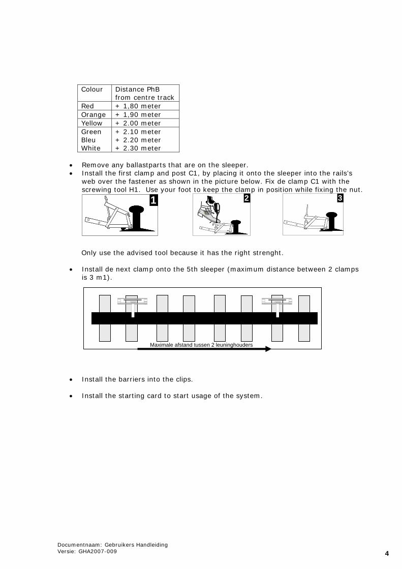
• Remove any ballastparts that are on the sleeper. • Install the first clamp and post C1, by placing it onto the sleeper into the rails’s
web over the fastener as shown in the picture below. Fix de clamp C1 with the screwing tool H1. Use your foot to keep the clamp in position while fixing the nut.
Only use the advised tool because it has the right strenght.
• Install de next clamp onto the 5th sleeper (maximum distance between 2 clamps is 3 m1).
• Install the barriers into the clips. • Install the starting card to start usage of the system.
1 2
Maximale afstand tussen 2 leuninghouders
3