ベトナム国 道路維持管理能力強化 プロジェクト プロ...
TRANSCRIPT
ベトナム社会主義共和国
運輸省 道路総局
ベトナム国
道路維持管理能力強化
プロジェクト
プロジェクト業務完了報告書
ITS 技術基準(QCVN/TCVN)策定支援
平成 26年 4月
(2014 年 4月)
独立行政法人
国際協力機構(JICA)
株式会社 片平エンジニアリング・インターナショナル
株式会社 オリエンタルコンサルタンツ
中日本高速道路 株式会社
14-082(3)
JR
基盤
目次
本文
1. 業務実施の背景 ····················································································· 1 2. 業務の目的 ························································································· 1 3. 技術基準の定義 ····················································································· 1 4. JICA専門家派遣での課題と実施した対応 ·················································· 3 5. JICA専門家によるドラフト QCVN/TCVNのレビュー結果 ···························· 4 6. QCVN/TCVN策定に向けた今後の課題と必要な対応 ··································· 4
添付資料
1. LOW ON STANDARDS AND TECHNICAL REGULATIONS ····························· 2. RECOMMENDATIONS AND REVIEWEDE RESULTS BY JICA EXPERT ············· 3. DRAFT QCVN OF TRAFFIC MONITORING AND MANAGEMENT FOR
EXPRESSWAYS ···················································································· 4. DRAFT QCVN OF CCTV CAMERA SYSTEM FOR EXPRESSWAYS ··················· 5. DRAFT QCVN OF VMS SYSTEM FOR EXPRESSWAYS ·································· 6. DRAFT QCVN OF COMMUNICATION SYSTEM FOR EXPRESSWAYS ·············· 7. DRAFT QCVN OF ETC SYSTEM FOR EXPRESSWAYS ·································· 8. MANAGEMENT CENTER/OFFICE FOR EXPRESSWAYS ································ 9. QCVN SCHEDULE ·················································································
1
ITS技術基準 (QCVN/TCVN) 策定支援
1. 業務実施の背景
ベトナムでは高速道路網が区間ごとに異なるドナーからの資金で建設されているため、
分割された道路ネットワークをいかにして統合的に運用管理するかが大きな課題になっ
ている。この課題に注目し、ベトナムにおける ITS 統合プロジェクトの実施と ITS 技術
基準の策定を目指して、「ベトナム国 ITS 技術基準・運用計画の策定支援調査業務」と
「ベトナム国国道 3号線およびハノイ大都市圏における ITS統合プロジェクト案件実施支
援調査 (SAPI) 」が、2012年までの 2年間にわたって実施された。
この一連の調査では、ITS マスタープランでベトナムにおける ITS に対するニーズとし
て整理した ITS 利用者サービスに対し、最適なシステムアーキテクチャとシステム方針
を論理的に導き出し、それに基づく形で ITS技術基準案を策定した。
その後の時間の経過に伴い、現在建設中の高速道路の ITSの統合や、今後建設予定の高
速道路を含めた統合的な ITS整備方法の確立は、ますますその緊急性を増しており、ベト
ナム政府は ITSの技術基準を策定することを 2012年末に決定した。JICAに対しては、そ
の支援が求められていた。
さらに、ITS 統合プロジェクトの実施予定機関になったものの、SAPI に至る一連の調
査に参画していないために ITS技術基準案についての理解が不足していたため、ベトナム
道路総局 (DRVN) の担当者の理解向上に向けた支援も併せて求められていた。
2. 業務の目的
SAPI で策定した ITS 技術基準案について、技術基準案の作成を担当する各 Sub-Group
および DRVN を含むベトナム側 ITS 関係者の理解の深化を支援し、それを踏まえた技術
基準の策定を支援することが、本業務の目的である。
3. 技術基準の定義
技術基準については、ベトナムの法律 (No: 68/2006/QH11: On standards and technical
regulations、Appendix-1) で下記の 2種類が規定されており、ITSの各分野の QCVN (また
は TCVN) の策定に向けて 8つの Sub-Groupが立ち上げられた。
QCVN (National Technical Regulation)
TCVN (National Technical Standards)
法律での記述は必ずしも明確ではないが、QCVN は技術基準の最上位に位置し全ての
プロジェクトが準拠すべき基本要件を規定するものである。それに対して、TCVNはプロ
ジェクトが参照すべき規定であり必ずしも準拠する必要はない。このような定義から、
TCVN には、QCVN の詳細規定として策定されるケースの他に、QCVN 策定の準備段階
として試作的に策定されるケースがあることも考慮するものとした。
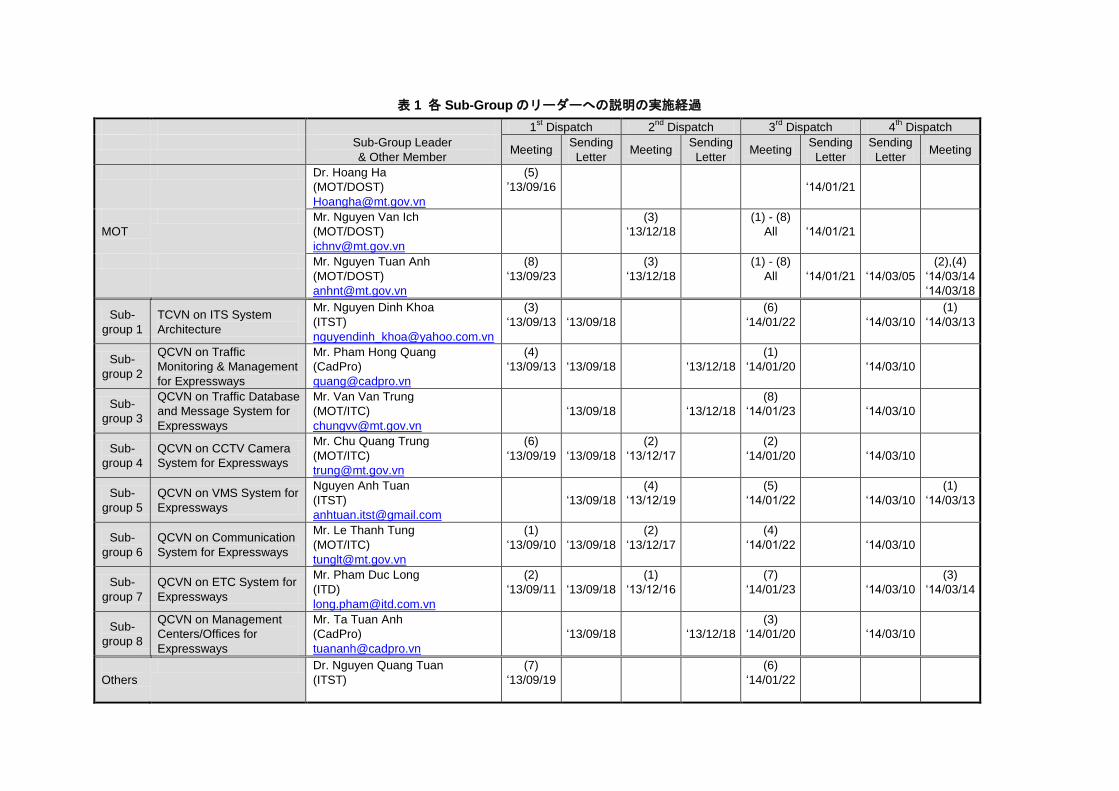
表 1 各 Sub-Groupのリーダーへの説明の実施経過
1st Dispatch 2
nd Dispatch 3
rd Dispatch 4
th Dispatch
Sub-Group Leader
& Other Member Meeting
Sending
Letter Meeting
Sending
Letter Meeting
Sending
Letter
Sending
Letter Meeting
Dr. Hoang Ha
(MOT/DOST)
(5)
’13/09/16
‘14/01/21
MOT
Mr. Nguyen Van Ich
(MOT/DOST)
(3)
‘13/12/18
(1) - (8)
All
‘14/01/21
Mr. Nguyen Tuan Anh
(MOT/DOST)
(8)
‘13/09/23
(3)
‘13/12/18
(1) - (8)
All
‘14/01/21
‘14/03/05
(2),(4)
‘14/03/14
‘14/03/18
Sub-
group 1
TCVN on ITS System
Architecture
Mr. Nguyen Dinh Khoa
(ITST)
(3)
‘13/09/13
‘13/09/18
(6)
‘14/01/22
‘14/03/10
(1)
‘14/03/13
Sub-
group 2
QCVN on Traffic
Monitoring & Management
for Expressways
Mr. Pham Hong Quang
(CadPro)
(4)
‘13/09/13
‘13/09/18
‘13/12/18
(1)
‘14/01/20
‘14/03/10
Sub-
group 3
QCVN on Traffic Database
and Message System for
Expressways
Mr. Van Van Trung
(MOT/ITC)
‘13/09/18
‘13/12/18
(8)
‘14/01/23
‘14/03/10
Sub-
group 4
QCVN on CCTV Camera
System for Expressways
Mr. Chu Quang Trung
(MOT/ITC)
(6)
‘13/09/19
‘13/09/18
(2)
‘13/12/17
(2)
‘14/01/20
‘14/03/10
Sub-
group 5
QCVN on VMS System for
Expressways
Nguyen Anh Tuan
(ITST)
‘13/09/18
(4)
‘13/12/19
(5)
‘14/01/22
‘14/03/10
(1)
‘14/03/13
Sub-
group 6
QCVN on Communication
System for Expressways
Mr. Le Thanh Tung
(MOT/ITC)
(1)
‘13/09/10
‘13/09/18
(2)
‘13/12/17
(4)
‘14/01/22
‘14/03/10
Sub-
group 7
QCVN on ETC System for
Expressways
Mr. Pham Duc Long
(ITD)
(2)
‘13/09/11
‘13/09/18
(1)
‘13/12/16
(7)
‘14/01/23
‘14/03/10
(3)
‘14/03/14
Sub-
group 8
QCVN on Management
Centers/Offices for
Expressways
Mr. Ta Tuan Anh
(CadPro)
‘13/09/18
‘13/12/18
(3)
‘14/01/20
‘14/03/10
Others
Dr. Nguyen Quang Tuan
(ITST)
(7)
‘13/09/19
(6)
‘14/01/22
3
4. JICA専門家派遣での課題と実施した対応
第1~4回の JICA 専門家派遣の中で、つぎの課題を抽出し、その解決のために以下の
通り必要な対応を実施した。
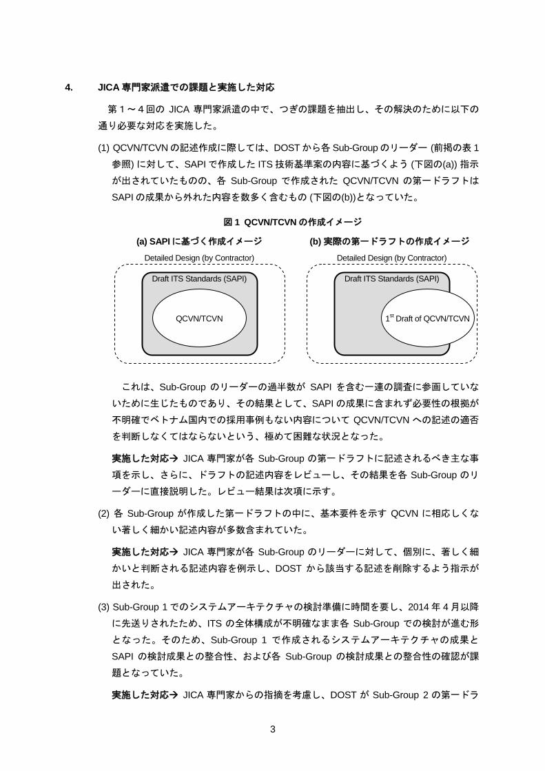
(1) QCVN/TCVNの記述作成に際しては、DOSTから各 Sub-Groupのリーダー (前掲の表 1
参照) に対して、SAPIで作成した ITS技術基準案の内容に基づくよう (下図の(a)) 指示
が出されていたものの、各 Sub-Group で作成された QCVN/TCVN の第一ドラフトは
SAPIの成果から外れた内容を数多く含むもの (下図の(b))となっていた。
図 1 QCVN/TCVNの作成イメージ
(a) SAPIに基づく作成イメージ (b) 実際の第一ドラフトの作成イメージ
これは、Sub-Group のリーダーの過半数が SAPI を含む一連の調査に参画していな
いために生じたものであり、その結果として、SAPIの成果に含まれず必要性の根拠が
不明確でベトナム国内での採用事例もない内容について QCVN/TCVN への記述の適否
を判断しなくてはならないという、極めて困難な状況となった。
実施した対応 JICA 専門家が各 Sub-Group の第一ドラフトに記述されるべき主な事
項を示し、さらに、ドラフトの記述内容をレビューし、その結果を各 Sub-Group のリ
ーダーに直接説明した。レビュー結果は次項に示す。
(2) 各 Sub-Group が作成した第一ドラフトの中に、基本要件を示す QCVN に相応しくな
い著しく細かい記述内容が多数含まれていた。
実施した対応 JICA 専門家が各 Sub-Group のリーダーに対して、個別に、著しく細
かいと判断される記述内容を例示し、DOST から該当する記述を削除するよう指示が
出された。
(3) Sub-Group 1でのシステムアーキテクチャの検討準備に時間を要し、2014年 4月以降
に先送りされたため、ITS の全体構成が不明確なまま各 Sub-Group での検討が進む形
となった。そのため、Sub-Group 1 で作成されるシステムアーキテクチャの成果と
SAPI の検討成果との整合性、および各 Sub-Group の検討成果との整合性の確認が課
題となっていた。
実施した対応 JICA 専門家からの指摘を考慮し、DOST が Sub-Group 2 の第一ドラ
Draft ITS Standards (SAPI)
Detailed Design (by Contractor)
Draft ITS Standards (SAPI)
Detailed Design (by Contractor)
QCVN/TCVN 1st Draft of QCVN/TCVN
4
フトに示される「Figuration Map of Components in Traffic Monitoring and Management
System for Expressways」の図を簡素化し、ベトナムの高速道路 ITS のシステムアー
キテクチャの代用とすることとした。これと並行して、Sub-Group 1 の成果を TCVN
とすることが DOSTおよびMOTにより決定された。
5. JICA専門家によるドラフト QCVN/TCVNのレビュー結果
各 Sub-Group で作成されたドラフト QCVN/TCVN を英訳 (Appendix-3~8)、その内容
をレビューして、前掲の表に示した日程で DOST、各 Sub-Group リーダーとのミーティ
ングを行い、レビュー結果として以下の事項を提示 (Appendix-2)、説明した。
(1) 各 Sub-Groupsの検討範囲
(2) QCVN/TCVNに記載すべき主要項目
(3) 交通情報・管制に不可欠な地域メインセンターの下での統合
(4) QCVN/TCVN第一ドラフトのレビューテーブル
(5) QCVN/TCVNに基本要件として記述すべき内容
6. QCVN/TCVN策定に向けた今後の課題と必要な対応
現在は Sub-Group 2, 4, 5, 6, 7, 8 が担当する QCVNの第一ドラフトが出揃った段階で
あり、以下の課題およびそれに対して必要な対応が残されている。
(1) ドラフトの最終化作業が比較的順調に進んでいる Sub-Group 2, 7, 8については、3月
末までに、MOT 関係機関からの意見収集をを終える予定 (Appendix-9) となっている。
必要な対応 3 月末以降のできる限り早い時期に、第 4 回 JICA 専門家派遣時に提示
した上記のレビュー結果を反映したドラフト修正結果を確認し、引続いて MOT 関係
機関からの指摘への対応の過程で SAPI との整合性を損なう修正が為されていないか
を確認、それに基づいた JICA専門家としてのコメントを提示する必要がある。
(2) TCVNに降格された Sub-Group 1を除く各 Sub-Groupのドラフトについては、3月末
以降 8月末までに、他省庁からの意見収集を終え、最終化する予定 (Appendix-9) とな
っている。
必要な対応 Sub-Group 2, 7, 8以外の第一ドラフトに対しても (1)と同様の対応を実
施し、他省庁に送られる前に、全ての Sub-Group のドラフトに対する JICA 専門家の
指摘について修正が完了したことを確認する必要がある。さらに、他省庁からの指摘
および対応の過程で SAPI との整合性を損なう修正が為されていないことを確認し、
JICA専門家としてのコメントを提示する必要がある。
8 月末までに他省庁からの意見収集を終える QCVN/TCVN 最終化の予定に鑑みて、(1)
と(2) に必要な対応は 7月までに終える必要があり、JICA専門家として 4月以降できる限
り空白期間のない対応が必要である。
添付資料-1
LOW ON STANDARDS AND TECHNICAL REGULATIONS
THE NATIONAL ASSEMBLY No: 68/2006/QH11
SOCIALIST REPUBLIC OF VIET NAM
Independence - Freedom - Happiness Ha Noi, day 29 month 06 year
2006
Law
On standards and technical regulations
(No. 68/2006/QH11)
Pursuant to the 1992 Constitution of the Socialist Republic of Vietnam, which was amended
and supplemented under December 25, 2001 Resolution No. 51/2001/QH10 of the Xth
National Assembly, the 10th session;
This Law provides for standards and technical regulations.
Chapter I
GENERAL PROVISIONS
Article 1.- Scope of regulation
This Law provides for the formulation, announcement and application of standards; the
formulation, promulgation and application of technical regulations; and the assessment of
conformity with standards and technical regulations.
Article 2.- Subjects of application
This Law applies to Vietnamese and foreign organizations and individuals and overseas
Vietnamese carrying out activities related to standards and technical regulations in Vietnam.
Article 3.- Interpretation of terms
In this Law, the terms below are construed as follows:
1. Standard means regulation on technical characteristics and management requirements used
as standard for classifying and appraising products, goods, services, processes, the
environment and other objects in socio-economic activities with a view to improving the
quality and effectiveness of these objects.
A standard shall be published in a written form by an organization for voluntary application.
2. Technical regulation means regulation on the limits of technical characteristics and
management requirements which products, goods, services, processes, the environment and
other objects in socio-economic activities must comply with in order to ensure safety,
hygiene and human health; to protect animals, plants and the environment; to safeguard
national interests and security, consumer interests and other essential requirements.
A technical regulation shall be promulgated in a written form by a competent state agency for
mandatory application.
3. Activities in the domain of standard means formulation, announcement and application of
standards and assessment of conformity with standards.
4. Activities in the domain of technical regulation means formulation, promulgation and
application of technical regulations and assessment of conformity with technical regulations.
5. Conformity assessment means determination as to whether objects of activities in the
domain of standard or objects of activities in the domain of technical regulation are
conformable with technical characteristics and management requirements in relevant
standards or technical regulations.
Conformity assessment covers testing, calibration, inspection and certification of standard or
technical regulation conformity; announcement of standard or technical regulation
conformity; and accreditation of the capacity of testing laboratories, calibration laboratories,
conformity certification organizations and inspection organizations.
6. Certification of standard conformity means certification that objects of activities in the
domain of standard conform with relevant standards.
7. Certification of technical regulation conformity means certification that objects of
activities in the domain of technical regulation conform with relevant technical regulations.
8. Announcement of standard conformity means announcement by an organization or
individual of the conformity of objects of activities in the domain of standard with relevant
standards.
9. Announcement of technical regulation conformity means announcement by an
organization or individual of the conformity of objects of activities in the domain of technical
regulation with relevant technical regulations.
10. Accreditation means certification that a testing laboratory, calibration laboratory,
conformity certification organization or inspection organization has the capacity conformable
with relevant standards.
Article 4.- Application of laws
1. In case of disparity between the provisions of this Law and those of other laws concerning
standards and technical regulations, the provisions of this Law shall prevail.
2. When a treaty to which the Socialist Republic of Vietnam is a contracting party contains
provisions different from those of this Law, the provisions of that treaty shall prevail.
Article 5.- Objects of activities in the domain of standard and objects of activities in domain
of technical regulation
1. Objects of activities in the domain of standard and objects of activities in the domain of
technical regulation include:
a/ Products, goods;
b/ Services;
c/ Processes;
d/ Environment;
e/ Other objects in socio-economic activities.
2. The Government shall stipulate in detail objects of activities in the domain of standard and
objects of activities in the domain of technical regulation.
Article 6.- Fundamental principles for activities in the domain of standard and the domain of
technical regulation
1. Standards and technical regulations must ensure improvement of the quality and efficiency
of socio-economic activities and raising of the competitiveness of products, goods and
services on domestic and international markets.
2. Standards and technical regulations must meet requirements on safety, national security,
hygiene, human health, legitimate rights and interests of related parties, protection of animals,
plants and the environment, and rational use of natural resources.
3. Activities in the domain of standard and the domain of technical regulation must ensure
publicity, transparency, non-discrimination and no unnecessary obstacles to production,
business and commercial activities. The formulation of standards must ensure involvement
and consensus of related parties.
4. The formulation of standards and technical regulations must:
a/ Be based on scientific and technological advances, practical experience, present-day needs
and socio-economic development trends.
b/ Use international standards, regional standards and foreign standards as the basis, except
for those not suitable to Vietnam's geographical, climatic, technical and technological
characteristics or those affecting national interests;
c/ Prioritize requirements on the utility of products and goods while restricting requirements
on descriptive characteristics or detailed design;
d/ Ensure uniformity of Vietnam's standard system and technical regulation system.
Article 7.- State policies on development of activities in the domain of standard and the
domain of technical regulation
1. To attach importance to investment in building material-technical foundations and training
human resources for the state management of activities in the domain of standard and the
domain of technical regulation.
2. To support and promote scientific research and application and technological development
in service of activities in the domain of standard and the domain of technical regulation.
3. To encourage domestic and foreign organizations and individuals as well as overseas
Vietnamese to participate in formulating and applying standards and technical regulations,
invest in developing activities in the domain of standard and the domain of technical
regulation in Vietnam, and training in standard and technical regulation knowledge for
econo-technical branches.
Article 8.- International cooperation on standards and technical regulations
1. The State shall encourage expansion of cooperation with other countries, territories,
international organizations, regional organizations, foreign organizations and individuals on
standards and technical regulations and making use of their assistance on the principle of
respect for the principles of independence, sovereignty, territorial integrity, equality and
mutual benefit.
2. The State shall facilitate and adopt measures to promote the signing of bilateral and
multilateral agreements on mutual recognition of conformity assessment results in order to
facilitate the development of trade between Vietnam and other countries and territories.
Article 9.- Prohibited acts
1. Taking advantage of activities in the domain of standard and the domain of technical
regulation to impede, trouble and hassle production, business and commercial activities of
organizations and individuals.
2. Disseminating false information and advertisements and committing other deceitful acts in
activities in the domain of standard and the domain of technical regulation.
3. Abusing activities in the domain of standard and the domain of technical regulation to
infringe upon national interests, defense, security, social order and safety.
Chapter II
FORMULATION, ANNOUNCEMENT AND APPLICATION OF STANDARDS
Article 10.- System of standards and standard symbols
The Vietnamese system of standards and standard symbols consists of:
1. National standards, symbolized by TCVN;
2. Manufacturer standards, symbolized by TCCS.
Article 11.- Responsibility for formulating, evaluating and announcing standards
1. Ministers, heads of ministerial-level agencies and heads of government-attached agencies
shall organize the drafting of national standards and request the evaluation and announcement
of national standards.
2. The Minister of Science and Technology shall organize the evaluation of draft national
standards and announce national standards.
3. Organizations formulating and announcing manufacturer standards include:
a/ Economic organizations;
b/ State agencies;
c/ Non-business organizations;
d/ Socio-professional organizations.
Article 12.- Types of standards
1. Fundamental standards stipulate characteristics and requirements of general application on
a large scale or contain general requirements for a particular domain.
2. Terminology standards stipulate names and definitions for objects of activities in the
domain of standard.
3. Technical requirement standards stipulate levels, criteria and requirements for objects of
activities in the domain of standard.
4. Testing method standards stipulate methods of sampling, methods of measurement,
methods of identification, methods of analysis, methods of checking, methods of assay and
methods of inspection of levels, criteria and requirements for objects of activities in the
domain of standard.
5. Labeling, packing, transportation and preservation standards stipulate requirements on
labeling, packing, transportation and preservation of products and goods.
Article 13.- Grounds for standard formulation
Standards shall be formulated on one or more of the following grounds:
1. International, regional and foreign standards;
2. Scientific and technological research results, technical advances;
3. Practical experience;
4. Results of evaluation, assay, testing, checking and inspection.
Article 14.- Plannings and plans on formulation of national standards
1. Plannings and plans on formulation of national standards include five-year plannings and

plans and annual plans which are elaborated on the following grounds:
a/ Socio-economic development requirements;
b/ Requests of organizations and individuals.
2. The Ministry of Science and Technology shall assume the prime responsibility for, and
coordinate with other concerned ministries, ministerial-level agencies and government-
attached agencies in, elaborating plannings and plans on formulation of national standards
and publish them for public comment before approving them.
The Ministry of Science and Technology shall approve plannings and plans on formulation of
national standards and publish them within thirty days after the date of approval thereof.
3. In case of necessity, plannings and plans on formulation of national standards may be
revised under decisions of the Minister of Science and Technology. The revision of plannings
and plans on formulation of national standards shall comply with the provisions of Clause 2
of this Article.
Article 15.- Rights of organizations and individuals to participate in formulating national
standards
1. To propose and give comments on plannings and plans on formulation of national
standards.
2. To assume the prime responsibility for, or participate in, compiling draft national standards
for the Ministry of Science and Technology to evaluate and announce.
3. To give comments on draft national standards.
Article 16.- Technical boards for national standard
1. A technical board for national standard is a technical advisory body set up by the Ministry
of Science and Technology for each domain of standard.
2. Members of a technical board for national standard include representatives of state
agencies, scientific and technological organizations, associations, unions, enterprises and
other concerned organizations, consumers and specialists.
3. A technical board for national standard has the following tasks:
a/ To propose plannings, plans, options and measures to formulate national standards;
b/ To compile draft national standards based on the drafts proposed by organizations or
individuals; to directly prepare draft national standards; to participate in compiling and
commenting on draft international standards, draft regional standards; to participate in
evaluating draft national standards formulated by ministries, ministerial-level agencies or
government-attached agencies;

c/ To join in counseling on and disseminating national standards and other standards;
d/ To participate in formulating draft technical regulations upon request.
Article 17.- Order and procedures for formulating, evaluating and announcing national
standards
1. The order and procedures for formulating, evaluating and announcing national standards
with respect to draft national standards formulated by ministries, ministerial-level agencies or
government-attached agencies are as follows:
a/ Ministries, ministerial-level agencies or government-attached agencies draft national
standards on the basis of the approved plans on formulation of national standards;
b/ Ministries, ministerial-level agencies or government-attached agencies organize public
gathering of opinions of concerned organizations and individuals on draft national standards;
hold symposiums for related parties to give comments on the drafts. The duration for
submission of opinions on a draft shall be at least sixty days; in urgent circumstances related
to health, safety or environment, this duration may be shorter;
c/ Ministries, ministerial-level agencies or government-attached agencies study and take
opinions of organizations and individuals into account for finalizing draft national standards,
make dossiers of draft national standards and send them to the Ministry of Science and
Technology for evaluation;
d/ The Ministry of Science and Technology organizes the evaluation of draft national
standards in accordance with the provisions of Article 18 of this Law. The evaluation
duration must not exceed sixty days from the date of receipt of valid dossiers;
e/ The Minister of Science and Technology announces national standards within thirty days
after obtaining evaluation opinions agreeing with draft national standards;
f/ When there are evaluation opinions disagreeing with the draft national standard, the
Ministry of Science and Technology shall forward such evaluation opinions to the national
standard-drafting ministry, ministerial-level agency or government-attached agency for
finalization of the draft national standard. After receiving the finalized draft, the Ministry of
Science and Technology shall announce the national standard in accordance with the
provisions of Point e of this Clause. If no agreement can be reached between two parties, the
Ministry of Science and Technology shall report the case to the Prime Minister for
consideration and decision.
2. The order and procedures for formulating, evaluating and announcing national standards
with respect to draft national standards proposed by organizations or individuals are as
follows:
a/ The organization or individual compiles a draft standard or proposes an existing standard
to the Ministry of Science and Technology for consideration;
b/ The Ministry of Science and Technology assigns the technical board for national standard
to compile a draft national standard on the basis of the draft proposed by the organization or
individual; organizes public gathering of opinions of concerned organizations and individuals
on the draft; holds symposiums for related parties to give comments on the draft. The
duration for submission of opinions on a draft shall be at least sixty days; in urgent
circumstances related to health, safety or environment, this duration may be shorter;
c/ The technical board for national standard studies and takes opinions of organizations and
individuals into account for finalizing the draft national standard, makes a dossier of the draft
and submits it to the Ministry of Science and Technology for consideration;
d/ The Ministry of Science and Technology organizes the evaluation of the draft national
standard under the provisions of Article 18 of this Law. The time limit for evaluation and
announcement of national standards shall comply with the provisions of Point d and e, Clause
1 of this Article.
3. The order and procedures for formulation, evaluation and announcement of national
standards with respect to draft national standards formulated by the Ministry of Science and
Technology are as follows:
a/ On the basis of the approved plan on formulation of national standards, the Ministry of
Science and Technology assigns a relevant technical board for national standard to formulate
the draft national standard under the provisions of Points b and c, Clause 2 of this Article;
b/ The Ministry of Science and Technology organizes the evaluation of the draft national
standard under the provisions of Article 18 of this Law. The time limit for evaluation and
announcement of national standards shall comply with the provisions of Point d and e, Clause
1 of this Article.
4. The Government shall issue specific regulations on dossiers of draft national standards.
Article 18.- Contents of evaluation of draft national standards
1. Conformity of standards with scientific and technological advances, socio-economic
conditions and development demands.
2. Conformity of standards with relevant technical regulations, legal provisions and
international commitments and the requirement on harmonization with international
standards.
3. Uniformity and consistency within the national standard system, adherence to the
principles of consensus and harmonization of interests of related parties.
4. Observance of technical requirements, the order and procedures for formulation of national
standards.
Article 19.- Review, amendment, supplementation, replacement and cancellation of national
standards
1. The Ministry of Science and Technology shall assume the prime responsibility for, and
coordinate with other ministries, ministerial-level agencies and government-attached agencies
in, reviewing national standards once every three years or at an earlier time when necessary,
counting from the date of announcement of such standards.
2. Amendment, supplementation and replacement of national standards shall be effected in
the order and according to the procedures specified in Article 17 of this Law on the basis of
national standard review results or at the proposal of organizations or individuals.
3. Cancellation of national standards shall be effected on the basis of national standard review
results or at the proposal of ministries, ministerial-level agencies, government-attached
agencies, organizations or individuals.
The Ministry of Science and Technology shall evaluate dossiers of cancellation of national
standards and announce the cancellation of national standards after obtaining written
agreement of other ministries, ministerial-level agencies or government-attached agencies
which have drafted such national standards.
Article 20.- Formulation and announcement of manufacturer standards
1. Manufacturer standards shall be formulated under the guidance of the heads of
organizations specified in Clause 3, Article 11 of this Law and announced for application to
manufacturers' activities.
2. Manufacturer standards shall be formulated on the basis of scientific and technological
achievements, demands and practical capabilities of manufacturers. The use of national
standards, international standards, regional standards and foreign standards as manufacturer
standards shall be encouraged.
3. Manufacturer standards must not contravene relevant technical regulations and provisions
of law.
4. The order and procedures for formulation and announcement of manufacturer standards
shall comply with the guidance of the Ministry of Science and Technology.
Article 21.- Publishing and distribution of standards
1. The Ministry of Science and Technology shall hold the right to publish and distribute
national standards.
2. Vietnamese representative agencies participating in international or regional standardizing
organizations shall publish and distribute international standards or regional standards
according to regulations of such organizations.
The publishing and distribution of standards of international or regional organizations of
which Vietnam is not a member and foreign standards shall be as agreed with organizations
promulgating those standards.
3. Organizations announcing manufacturer standards shall hold the right to publish and
distribute those manufacturer standards.
Article 22.- Notification and dissemination of national standards
The Ministry of Science and Technology has the following responsibilities:
1. To make public the announcement of national standards, the amendment, supplementation,
replacement or cancellation of national standards within thirty days after the date of issuance
of relevant decisions;
2. To assume the prime responsibility for, and coordinate with other ministries, ministerial-
level agencies and government-attached agencies in, disseminating and guiding the
application of national standards;
3. Annually, to distribute the list of national standards.
Article 23.- Principles for application of standards
1. Standards shall be applied on the principle of voluntariness.
The application of part or the whole of a specific standard shall become mandatory when it is
invoked in a legal document or technical regulation.
2. Manufacturer standards shall be applied within the scope of management of organizations
that announce them.
Article 24.- Modes of application of standards
1. Standards shall be directly applied or invoked in another document.
2. Standards shall be used as the basis for conformity assessment activities.
Article 25.- Funding sources for formulation of standards
1. Funding sources for formulation of national standards include:
a/ State budget allocated according to approved annual budget estimates;
b/ Voluntary supports of organizations and individuals at home and abroad;
c/ Other lawful sources of revenues.
2. Manufacturer standards shall be formulated with organizations' or individuals' own funds,
which shall be accounted as reasonable expenses.
3. The Government shall stipulate the management and use of funds for formulation of
national standards.
Chapter III
FORMULATION, PROMULGATION AND APPLICATION OF TECHNICAL
REGULATIONS
Article 26.- System of technical regulations and symbols of technical regulations
The system of technical regulations and symbols of technical regulations of Vietnam consists
of:
1. National technical regulations, symbolized by QCVN;
2. Local technical regulations, symbolized by QCDP.
Article 27.- Responsibilities for formulating, evaluating and promulgating technical
regulations
1. Responsibilities for formulating, evaluating and promulgating national technical
regulations are as follows:
a/ Ministers and heads of ministerial-level agencies shall formulate and promulgate national
technical regulations within the scope of branches or domains under their assigned
management;
b/ The Minister of Science and Technology shall organize evaluation of draft national
technical regulations;
c/ The Government shall stipulate the formulation, evaluation and promulgation of national
technical regulations of inter-branch nature and national technical regulations for objects of
activities in the domain of technical regulation falling under the management of government-
attached agencies.
2. Responsibilities for formulating, evaluating and promulgating local technical regulations
are as follows:
a/ People's Committees of provinces or centrally run cities shall formulate and promulgate
local technical regulations for application within the scope of local management to specific
products, goods, services and processes of each locality and in response to specific
environmental requirements suitable to local geographical, climatic, hydrological
characteristics and socio-economic development levels;
b/ Local technical regulations shall be promulgated after they are approved by competent
state agencies defined at Point a, Clause 1 of this Article.
Article 28.- Types of technical regulations
1. General technical regulations include technical and managerial regulations applicable to a
management domain or a group of products, goods, services or processes.
2. Safe technical regulations include:
a/ Regulations on levels, norms and requirements related to bio-safety, fire and explosion
safety, mechanical safety, industrial safety, construction safety, thermal safety, chemical
safety, electricity safety, medical equipment safety, electro-magnetic compatibility, radiation
and nuclear safety;
b/ Regulations on levels, norms and requirements related to food safety and hygiene,
pharmaceutical and cosmetic safety for human health;
c/ Regulations on levels, norms and requirements related to hygiene and safety of animal
feeds, fertilizers, plant protection drugs, veterinary drugs, bio-products and chemicals used
for animals and plants.
3. Environmental technical regulations provide for levels, norms and requirements on
environmental quality and waste.
4. Technical regulations of processes provide for requirements on hygiene and safety in the
processes of production, exploitation, processing, preservation, operation, transportation, use
and maintenance of products and goods.
5. Technical regulations of services provide for requirements on hygiene and safety in
business, trading, post, telecommunications, construction, education, financial, scientific and
technological, healthcare, tourist, entertainment, cultural, sport, transport, environmental
services and services in other domains.
Article 29.- Plannings and plans on formulation of technical regulations
1. Plannings and plans on formulation of technical regulations include five-year plannings
and plans and annual plans elaborated on the following grounds:
a/ Socio-economic development requirements;
b/ State management requirements;
c/ Proposals of organizations and individuals.
2. Plannings and plans on formulation of technical regulations shall be elaborated by
technical regulation-promulgating agencies in coordination with the Ministry of Science and
Technology and concerned agencies and put up for public comment before they are approved.
Technical regulation-promulgating agencies shall approve plannings and plans on
formulation of technical regulations and make them public within thirty days after approval.
3. In case of necessity, plannings and plans on formulation of technical regulations may be
amended and supplemented under decisions of the heads of technical regulation-
promulgating agencies and in accordance with Clause 2 of this Article.
Article 30.- Grounds for formulation of technical regulations
Technical regulations shall be formulated on one or more of the following grounds:
1. National standards;
2. International standards, regional standards and foreign standards;
3. Scientific and technological research results, technical advances;
4. Results of evaluation, assay, test, supervision and inspection.
Article 31.- Rights of organizations and individuals to participate in formulating technical
regulations
1. To propose and give comments on plannings and plans on formulation of technical
regulations.
2. To compile draft technical regulations and propose them to technical regulations-
promulgating agencies for consideration and promulgation.
3. To participate in compiling draft technical regulations at the request of technical
regulations-formulating agencies.
4. To give comments on draft technical regulations.
Article 32.- Order and procedures for formulation, evaluation and promulgation of technical
regulations
1. The order and procedures for formulation, evaluation and promulgation of national
technical regulations are as follows:
a/ On the basis of the approved plan on formulation of technical regulations, the national
technical regulation-promulgating agency defined in Article 27 of this Law organizes the
formulation of the national technical regulation with the participation of representatives of
state agencies, scientific and technological institutions, enterprises, other related
organizations, consumers and specialists;
b/ The national technical regulation-promulgating agency organizes public gathering of
opinions of concerned organizations and individuals on the draft national technical
regulation; holds symposiums for related parties to give comments on the draft. The duration
for submission of opinions on the draft shall be at least sixty days; in urgent circumstances
related to health, safety or environment, this duration may be shorter as decided by the
national technical regulations-promulgating agency;
c/ The national technical regulation-promulgating agency studies and takes opinions of
organizations and individuals into account for finalizing the draft national technical
regulation, makes a dossier of the draft national technical regulation after consulting
concerned ministries and branches on the contents of the draft and transfers the draft to the
Ministry of Science and Technology for evaluation;
d/ The Ministry of Science and Technology organizes the evaluation of the draft national
technical regulation in accordance with the provisions of Article 33 of this Law. The time
limit for evaluation shall not exceed sixty days from the date of receipt of the valid dossier;
e/ The national technical regulation-promulgating agency finalizes the draft and promulgates
the national technical regulation within thirty days after the date of obtaining the agreement
of the evaluating agency. In case of disagreeing with the evaluation opinions, the national
technical regulation-promulgating agency shall report the case to the Prime Minister for
consideration and decision.
2. The order and procedures for formulating, evaluating and promulgating local technical
regulations are as follows:
a/ On the basis of the approved plan on formulation of technical regulations, the
provincial/municipal People's Committee organizes the formulation of local technical
regulation;
b/ The provincial/municipal People's Committee organizes public gathering of opinions of
concerned organizations and individuals on the draft local technical regulation; holds
symposiums for related parties to give comments on the draft. The duration for submission of
opinions on the draft shall be at least sixty days; in urgent circumstances related to health,
safety or environment, this duration may be shorter as decided by the provincial/municipal
People's Committee;
c/ The provincial/municipal People's Committee studies and takes opinions of organizations
and individuals into account for finalizing the draft local technical regulation, makes a dossier
of the draft and sends it to the competent state agency defined at Point a, Clause 1, Article 27
of this Law for comment;
d/ The provincial/municipal People's Committee promulgates the local technical regulation
within thirty days after the date of obtaining the agreement of the competent state agency
defined at Point a, Clause 1, Article 27 of this Law.
3. The Government shall issue specific regulations on dossiers of draft technical regulations.
Article 33.- Contents of evaluation of draft national technical regulations
1. Conformity of technical regulations with relevant legal provisions and international
commitments;
2. Uniformity and consistency within the system of national technical regulations;
3. Observance of professional requirements, the order and procedures for formulation of
technical regulations.
Article 34.- Implementation effect of technical regulations
1. Technical regulations take effect at least six months after the date of promulgation, except
for the case defined in Clause 2 of this Article.
2. In emergency circumstances related to health, safety or environment, a technical regulation
may take effect earlier as decided by the technical regulation-promulgating agency.
3. National technical regulations take effect nationwide; local technical regulations take effect
in localities under the management of the promulgating provincial/municipal People's
Committees.
Article 35.- Review, amendment, supplementation, replacement and cancellation of technical
regulations
1. Technical regulation-promulgating agencies shall organize reviews of technical regulations
once every five years or at an earlier time when necessary, counting from the date of
promulgation of such technical regulations.
2. Amendment, supplementation and replacement of technical regulations shall be effected in
the order and according to the procedures specified in Article 32 of this Law on the basis of
review results or at the request of organizations or individuals.
3. Technical regulation-promulgating agencies may cancel technical regulations in the
following order:
a/ On the basis of review results or at the request of organizations or individuals, the national
technical regulation-promulgating agency organizes the compilation of a dossier of
cancellation of the national technical regulation in question; examines the dossier and makes
a decision to cancel the national technical regulation after obtaining the evaluation opinion of
the Ministry of Science and Technology;
b/ On the basis of review results or at the request of organizations or individuals, the
provincial/municipal People's Committee organizes the compilation of a dossier of
cancellation of the local technical regulation in question; examines the dossier and makes a
decision to cancel the local technical regulation after obtaining the evaluation opinion of the
competent state agency defined at Point a, Clause 1, Article 27 of this Law.
Article 36.- Notification, dissemination, registration, publishing and distribution of technical
regulations
1. Technical regulation-promulgating agencies have the following responsibilities:
a/ To make public the promulgation, amendment, supplementation, replacement or
cancellation of technical regulations within thirty days after the date of issuance of relevant
decisions;
b/ To organize dissemination, guidance and application of technical regulations;
c/ To send technical regulation documents to the Ministry of Science and Technology for
registration;
d/ To publish and distribute technical regulations.
2. Annually, the Ministry of Science and Technology shall distribute a list of technical
regulations.
Article 37.- Responsibility for applying technical regulations
1. Organizations and individuals shall apply relevant technical regulations.
2. In the course of application of technical regulations, organizations and individuals shall
promptly report problems or point out inappropriate contents to the technical regulation-
promulgating agencies for consideration and settlement.
Technical regulation-promulgating agencies shall respond in writing within thirty days after
receiving reports or recommendations of organizations and individuals.
Article 38.- Principles for and methods of application of technical regulations
1. The application of technical regulations to production, business and other socio-economic
activities is mandatory.
2. Technical regulations shall be used as the basis for conformity assessment activities.
Article 39.- Funding sources for formulation of technical regulations
1. Funding sources for formulation of technical regulations include:
a/ State budget allocated according to approved annual budget estimates;
b/ Voluntary supports of organizations and individuals at home and abroad.
2. The Government shall detail the management and use of funds for formulation of technical
regulations.
Chapter IV
ASSESSMENT OF CONFORMITY WITH STANDARDS AND TECHNICAL
REGULATIONS
Section 1. GENERAL PROVISIONS ON CONFORMITY ASSESSMENT
Article 40.- Fundamental requirements on conformity assessment
1. Keeping related parties informed of the conformity assessment order and procedures in a
public and transparent manner.
2. Keeping confidential information and data of organizations for which conformity
assessment is conducted.
3. Ensuring non-discrimination against production and business organizations and individuals
or the origin of products, goods, services or processes.
4. The conformity assessment order and procedures shall comply with regulations
promulgated by related international organizations.
Article 41.- Forms of conformity assessment
1. Assessment of conformity with standards or technical regulations shall be conducted by
conformity assessment organizations or conformity announcement organizations or
individuals themselves.
2. Assessment of conformity with standards shall be conducted on a voluntary basis at the
request of organizations or individuals in the form of testing, inspection, standard conformity
certification or standard conformity announcement.
3. Assessment of conformity with technical regulations shall be conducted on a mandatory
basis according to state management requirements in the form of testing, inspection,
technical-regulation conformity certification or technical-regulation conformity
announcement.
Article 42.- Requirements for standards and technical regulations used for conformity
assessment
Standards and technical regulations used for conformity assessment must be those that
stipulate specific technical characteristics and managerial requirements that can be assessed
with methods and means available at home or abroad.
Article 43.- Standard conformity marks, technical-regulation conformity marks
1. Standard conformity marks and technical-regulation conformity marks are proof of
conformity of products or goods with relevant standards or technical regulations.
2. Standard conformity marks shall be granted to products or goods after their standard
conformity is certified.
3. Technical-regulation conformity marks shall be granted to products or goods after their
technical-regulation conformity is certified and announced.
Section 2. ASSESSMENT OF CONFORMITY WITH STANDARDS
Article 44.- Certification of standard conformity
1. Certification of standard conformity shall be effected under the agreement between
organizations or individuals requesting certification and conformity certification
organizations defined in Article 50 of this Law.
2. Standards used for certification of standard conformity must be national standards,
international standards, regional standards or foreign standards satisfying requirements
specified in Article 42 of this Law.
Article 45.- Announcement of standard conformity
1. Organizations and individuals shall announce the conformity of products, goods, services,
processes or environment with relevant standards on the basis of the results of certification of
standard conformity conducted by conformity certification organizations or the results of
their self-assessment of conformity.
2. Organizations and individuals announcing standard conformity shall register their written
standard conformity announcements with competent state agencies.
Article 46.- Rights and obligations of organizations and individuals requesting certification of
standard conformity
1. Organizations and individuals requesting certification of standard conformity have the
following rights:
a/ To select standard conformity certification organizations;
b/ To be granted standard conformity certificates for their products, goods, services,
processes and environment already certified to be standard-conformable;
c/ To use standard conformity marks for products and goods already certified to be standard-
conformable, packings thereof, and in documents on such products and goods;
d/ To lodge complaints about results of standard conformity certification conducted or
breaches committed by conformity certification organizations in relation to standard
conformity certification contracts.
2. Organizations and individuals requesting certification of standard conformity have the
following obligations:
a/ To ensure conformity of products, goods, services, processes and environment with
standards used for standard conformity certification;
b/ To display accurately information written in standard conformity certificates on products
and goods and packings thereof and in documents on objects already certified to be standard-
conformable;
c/ To notify standard conformity certification organizations of change or addition of
standards used for standard conformity certification;
d/ To pay expenses for standard conformity certification.
Section 3. ASSESSMENT OF CONFORMITY WITH TECHNICAL REGULATIONS
Article 47.- Certification of technical-regulation conformity
1. Certification of technical-regulation conformity is mandatory for products, goods, services,
processes and environment which are objects defined in relevant technical regulations.
2. Technical regulations used for certification of technical-regulation conformity are national
or local technical regulations meeting the requirements specified in Article 42 of this Law.
3. Ministries, ministerial-level agencies and provincial/municipal People's Committees
defined in Clause 1 and Clause 2, Article 27 of this Law shall designate organizations to
certify conformity with technical regulations issued by themselves on the basis of considering
and selecting conformity certification organizations defined in Article 50 of this Law.
4. Conformity certification organizations may be designated to conduct regulation conformity
certification by modes prescribed by competent state agencies.
Article 48.- Announcement of technical-regulation conformity
1. Production and business organizations and individuals subject to application of technical
regulations shall announce the conformity of products, goods, services, processes and
environment with relevant technical regulations on the basis of results of certification of
technical-regulation conformity by conformity certification organizations designated under
the provisions of Clause 3, Article 47 of this Law or results of their self-assessment
conducted on the basis of testing results of accredited or designated testing laboratories.
2. Organizations and individuals announcing technical-regulation conformity shall register
their technical-regulation conformity announcement documents with competent state
agencies.
Article 49.- Rights and obligations of organizations and individuals requesting certification of
technical-regulation conformity
1. Organizations and individuals requesting certification of technical-regulation conformity
have the following rights:
a/ To select conformity certification organizations already designated under the provisions of
Clause 3, Article 47 of this Law;
b/ To be granted technical-regulation conformity certificates for their products, goods,
services, processes and environment already certified as such;
c/ To use technical-regulation conformity marks for products and goods already certified or
announced to be technical regulation-conformable, packings thereof, and in documents on
such products and goods;
d/ To lodge complaints about results of technical-regulation conformity certification
conducted or breaches committed by conformity certification organizations in relation to
contracts on technical-regulation conformity certification.
2. Organizations and individuals requesting certification of technical-regulation conformity
have the following obligations:
a/ To ensure conformity of products, goods, services, processes and environment with
relevant technical regulations;
b/ To display accurately information written in technical-regulation conformity certificates
and announcement documents on products and goods and packings thereof and in documents
on objects already certified and announced to be technical regulation-conformable;
c/ To supply, upon request of a competent state agency or conformity certification
organization, documents evidencing the assurance of the conformity of products, goods,
services, processes and environment with relevant technical regulations;
d/ To suspend the provision of products, goods, services or processes failing to conform with
relevant technical regulations according to decisions of competent state agencies;
e/ To pay a fee for technical-regulation conformity certification.
Section 4. CONFORMITY CERTIFICATION ORGANIZATIONS
Article 50.- Conformity certification organizations
1. Non-business units providing technical services.
2. Enterprises.
3. Vietnam-based branches of foreign certification organizations.
Article 51.- Operation conditions of conformity certification organizations
A conformity assessment organization must satisfy the following conditions:
1. Having an organizational apparatus and capability meeting requirements in national
standards and international standards for conformity certification organizations;
2. Having established and maintained a management system meeting requirements in national
and international standards.
3. Having registered standard conformity and technical-regulation conformity activities with
a competent state agency.
Article 52.- Rights and obligations of conformity certification organizations
1. Conformity certification organizations have the following rights:
a/ To grant standard conformity or technical-regulation conformity certificates for products,
goods, services, processes and environment conformable to standards or technical
regulations;
b/ To assign the right to use standard conformity or technical-regulation conformity marks to
organizations and individuals having products and goods already certified to be standard- or
technical regulation-conformable;
c/ To withdraw granted standard conformity or technical-regulation conformity certificates
and the assigned right to use standard conformity or technical-regulation conformity marks.
2. Conformity certification organizations have the following obligations:
a/ To certify standard conformity or technical-regulation conformity in the registered
domains under contracts signed with certification-requesting organizations or individuals;
b/ To ensure objectivity and fairness in standard conformity or technical-regulation
conformity certification activities; to refrain from giving consultancy to certification-
requesting organizations or individuals;
c/ To keep confidential information collected in the course of conducting certification;
d/ To supervise certified objects in order to ensure their sustained conformity with relevant
standards or technical regulations;
e/ To take responsibility before law for their activities;
f/ To widely announce on the mass media the withdrawal of standard conformity or technical-
regulation conformity certificates and the right to use standard conformity or technical-
regulation conformity marks.
Section 5. MUTUAL ACCREDITATION AND RECOGNITION
Article 53.- Accreditation
1. Accreditation shall be conducted with respect to the following organizations:
a/ Testing laboratories;
b/ Calibration laboratories;
c/ Conformity certification organizations;
d/ Inspection organizations.
2. Accreditation shall be conducted on the basis of national standards and international
standards.
3. Accreditation shall be conducted by accreditation organizations specified in Article 54 of
this Law.
Article 54.- Accreditation organizations
1. Accreditation organizations are non-business scientific units conducting assessment and
accreditation of the capabilities of organizations defined in Clause 1, Article 53 of this Law.
2. Accreditation organizations must meet the following conditions:
a/ Having an organizational apparatus and capability satisfying requirements in national
standards and international standards for accreditation organizations; having been recognized
by international and regional accreditation organizations;
b/ Operating in accordance with requirements in national standards and international
standards for accreditation organizations;
c/ Having established and maintained a management system meeting requirements in national
standards and international standards;
d/ Operating in an independent and objective manner.
3. The Minister of Science and Technology shall stipulate organization and operation of
accreditation organizations.
Article 55.- Rights and obligations of accreditation organizations
1. Accreditation organizations have the following rights:
a/ To grant accreditation certificates to organizations defined in Clause 1, Article 53 of this
Law;
b/ To withdraw accreditation certificates.
2. Accreditation organizations have the following obligations:
a/ To carry out accreditation at the request of organizations or individuals;
b/ To ensure objectivity and fairness in accreditation activities; refrain from giving
consultancy to accreditation-requesting organizations specified in Clause 1, Article 53 of this
Law;
c/ To keep confidential information collected in the course of conducting accreditation;
d/ To supervise accredited organizations in order to ensure their sustained capabilities in
conformity with relevant standards;
e/ To take responsibility before law for their activities.
Article 56.- Rights and obligations of accredited organizations:
1. Accredited organizations have the following rights:
a/ To propose competent state agencies to use results of conformity assessment activities with
respect to certification, testing, calibration and inspection already accredited to serve state
management requirements;
b/ To lodge complaints about accreditation results issued by accreditation organizations or
their breaches of the undertaking to conduct accreditation;
c/ Conformity certification organizations specified at Point c, Clause 1, Article 53 of this Law
shall also have the rights provided in Clause 1, Article 52 of this Law.
2. Accredited organizations have the following obligations:
a/ To ensure conformity of their accredited organizational apparatus and capability with
requirements in relevant national standards and international standards;
b/ To maintain a management system meeting requirements in relevant national standards and
international standards;
c/ To ensure objectivity and fairness in conformity assessment activities;
d/ Conformity certification organizations specified at Point c, Clause 1, Article 53 of this Law
shall also perform the obligations defined in Clause 2, Article 52 of this Law;
e/ To pay a fee for accreditation.
Article 57.- Mutual recognition agreements
1. Mutual recognition agreements include:
a/ The recognition by Vietnam and other countries or territories of one another's conformity
assessment results shall comply with treaties to which the Socialist Republic of Vietnam is a
contracting party;
b/ The recognition by Vietnamese conformity assessment organizations and conformity
assessment organizations of other countries or territories of one another's conformity
assessment results shall be effected on their agreements.
2. The Ministry of Science and Technology shall assume the prime responsibility for, and
coordinate with other concerned ministries and ministerial-level agencies in, organizing the
implementation of mutual recognition agreements mentioned in Clause 1 of this Law.
Chapter V
RESPONSIBILITIES OF AGENCIES, ORGANIZATIONS AND INDIVIDUALS
OPERATING IN THE DOMAIN OF STANDARD AND THE DOMAIN OF
TECHNICAL REGULATION
Article 58.- Responsibilities of the Government
The Government shall perform the unified state management of activities in the domain of
standard and the domain of technical regulation.
Article 59.- Responsibilities of the Ministry of Science and Technology
1. The Ministry of Science and Technology shall take responsibility to the Government for
performing uniform state management of activities in the domain of standard and the domain
of technical regulation.
2. The Ministry of Science and Technology has the following responsibilities:
a/ To formulate and promulgate or submit to competent state agencies or persons for
promulgation, and organize the implementation of, policies and strategies on activities in the
domain of standard and the domain of technical regulation; organize the elaboration and
approval of plannings and plans on formulation of national standards and national technical
regulations in the domains under their assigned management;
b/ To formulate and promulgate or submit to competent state agencies or persons for
promulgation legal documents on standards and technical regulations, and organize the
implementation thereof;
c/ To evaluate and announce national standards; organize formulation and announcement of
national standards in the domain under its assigned management; to promulgate organization
and operation regulations of technical boards for national standards; to guide the formulation
and application of national standards; to guide the formulation and announcement of
manufacturer standards; to guide the application of international, regional and foreign
standards;
d/ To evaluate national technical regulations; to guide the formulation of technical
regulations; to organize the formulation and promulgation of national technical regulations in
the domain under its assigned management;
e/ To manage and guide conformity assessment activities;
f/ To build and develop human resources for activities in the domain of standard and the
domain of technical regulation; to organize scientific research and technological development
related to standards and technical regulations;
g/ To manage international cooperation on standards and technical regulations;
h/ To organize and manage activities of the national network of notification and enquiry
points related to standards, technical regulations and conformity assessment;
i/ To conduct propaganda about and guidance on the observance of the law on standards and
technical regulations; to make statistics on the domain of standard and the domain of
technical regulation;
j/ To supervise and inspect the observance of law on standards and technical regulations; to
handle violations in accordance with law; to settle complaints and denunciations related to
activities in the domain of standard and the domain of technical regulation in accordance with
the law on complaints and denunciations.
Article 60.- Responsibilities of ministries, ministerial-level agencies and government-
attached agencies
1. Ministries and ministerial-level agencies, within the scope of their respective tasks and
powers, have the following responsibilities:
a/ To formulate and promulgate or submit to competent state agencies or competent persons
for promulgation legal documents on relevant standards and technical regulations;
b/ To organize the elaboration and approval of plannings and plans on formulation on
national technical regulations; to organize the formulation and promulgation of national
technical regulations in the domains under their respective management;
c/ To propose plannings and plans on formulation of national standards; to organize the
formulation of draft national standards in the branches or domains under their respective
management;
d/ To manage the formulation and promulgation of local technical regulations; to give
comments on draft local technical regulations;
e/ To manage activities of announcement of technical-regulation conformity and certification
of technical-regulation conformity;
f/ To make statistics on activities of formulation, promulgation and application of technical
regulations issued by themselves;
g/ To participate in international cooperation on standards and technical regulations;
h/ To disseminate, and guide the application of, standards and technical regulations;
i/ To supervise and inspect activities in the domain of technical regulation; to handle
violations in accordance with law;
j/ To settle complaints and denunciations related to activities in the domain of technical
regulation in accordance with the law on complaints and denunciations;
2. Government-attached agencies, within the scope of their tasks and powers, have the
following responsibilities:
a/ To formulate and submit to competent state agencies or persons for promulgation legal
documents on relevant standards and technical regulations;
b/ To elaborate and submit to competent state agencies or persons for approval plannings and
plans on formulation of national technical regulations;
c/ To organize the formulation of draft national technical regulations; to guide the
formulation of local technical regulations; to give comments on draft local technical
regulations;
d/ To propose plannings and plans on formulation of national standards; to organize the
formulation of draft national standards in the domains under their assigned management;
e/ To disseminate, and guide the application of, standards and technical regulations;
f/ To participate in international cooperation on standards and technical regulations;
g/ To supervise and inspect activities in the domain of technical regulation; to handle
violations in accordance with law;
h/ To settle complaints and denunciations related to activities in the domain of technical
regulation in accordance with the law on complaints and denunciations.
Article 61.- Responsibilities of provincial/municipal People's Committees
Provincial/municipal People's Committees, within the scope of their tasks and powers, have
the following responsibilities:
1. To propose plans on formulation of national standards and national technical regulations;
to organize the elaboration and implementation of plans on formulation of local technical
regulations.
2. To promulgate, and guide the application of, local technical regulations.
3. To build necessary material and technical foundations for activities in the domain of
standard and domain of technical regulation in localities.
4. To organize the implementation of, propaganda about and education in the law on
standards and technical regulations.
5. To supervise and inspect the observance of the law on standards and technical regulations;
to handle violations in accordance with law.
6. To settle complaints and denunciations related to activities in the domain of standards and
the domain of technical regulation in accordance with the law on complaints and
denunciations.
Article 62.- Responsibilities of production and business organizations and individuals
1. To announce standards applicable to products, goods, services, processes and environment.
2. To announce products, goods, services, processes and environment conformable with
relevant technical regulations.
3. To ensure conformity of products, goods, services, processes and environment with
announced technical regulations and standards.
Article 63.- Responsibilities of associations and unions
1. To give opinions on the formulation of relevant legal documents, national standards and
technical regulations.
2. To disseminate and train their members in the knowledge about and provide necessary
information on activities in the domain of standard and the domain of technical regulation
among their members and competent state agencies in accordance with law.
Chapter VI
INSPECTION, HANDLING OF VIOLATIONS, SETTLEMENT OF COMPLAINTS
AND DENUNCIATIONS AND DISPUTES RELATED TO ACTIVITIES IN THE
DOMAIN OF STANDARD AND THE DOMAIN OF TECHNICAL REGULATION
Article 64.- Inspectorate of activities in the domain of standard and the domain of technical
regulation
1. The inspectorate of activities in the domain of standard and the domain of technical
regulation is a specialized inspectorate.
2. Inspection of activities in the domain of standard and the domain of technical regulation
shall be conducted in accordance with the law on inspection.
3. The Government shall issue detailed regulations on the organization and operation of the
inspectorate of activities in the domain of standard and the domain of technical regulation.
Article 65.- Handling of violations of the law on standards and technical regulations
1. Persons who commit acts of violating the law on standards and technical regulations shall,
depending on the nature and severity of their violations, be disciplined, administratively
sanctioned or examined for penal liability; if causing damage, they must pay compensation
therefor in accordance with law.
2. Organizations that violate the law on standards and technical regulations shall, depending
on the nature and severity of their violations, be administratively sanctioned or suspended
from operation; if causing damage, they must pay compensation therefor in accordance with
law.
Article 66.- Complaints and denunciations related to activities in the domain of standard and
the domain of technical regulation
1. Organizations and individuals are entitled to lodge complaints with competent state
agencies or persons about the latter's administrative decisions or administrative acts which
they deem illegal or about acts of infringing upon their legitimate rights and interests in
activities in the domain of standard and the domain of technical regulation in accordance with
law.
2. Individuals are entitled to denounce to competent state agencies or competent persons acts
of violation of the law on standards and technical regulations.
Article 67.- Settlement of complaints and denunciations related to activities in the domain of
standard and the domain of technical regulation
State agencies and persons competent to settle complaints and denunciations shall consider
and settle complaints and denunciations related to activities in the domain of standard and the
domain of technical regulation in accordance with the law on complaints and denunciations.
Article 68.- Resolution of disputes in activities in the domain of standard and the domain of
technical regulation
The State shall encourage parties to disputes in activities in the domain of standard and the
domain of technical regulation to resolve their disputes through conciliation; in case of
conciliation failure, the parties may initiate lawsuits at a court or an arbitration in accordance
with law.
Chapter VII
IMPLEMENTATION PROVISIONS
Article 69.- Transition provisions
1. Vietnam standards and branch standards already promulgated under the 1999 Ordinance on
Goods Quality and under other laws and ordinances shall be reviewed and converted into
national standards or national technical regulations.
2. Technical regulations, processes, rules, standards and documents already promulgated for
mandatory application in service of state management shall be reviewed and converted into
technical regulations.
3. The Government shall provide for the conversion of branch standards into national
standards or national technical regulations defined in Clause 1 of this Article and the
conversion of technical regulations, processes, rules, standards and documents subject to
mandatory application into technical regulations defined in Clause 2 of this Article.
Article 70.- Implementation effect
This Law takes effect on January 1, 2007.
Article 71.- Implementation guidance
The Government shall detail and guide the implementation of this Law.
This Law was passed on June 29, 2006, by the XIth National Assembly of the Socialist
Republic of Vietnam at its 9th session.
THE NATIONAL
ASSEMBLY
CHAIRMAN
(signed)
Nguyen Phu Trong

添付資料-2
RECOMMENDATIONS AND REVIEWEDE RESULTS
BY JICA EXPERT
(2014.03.31)
1
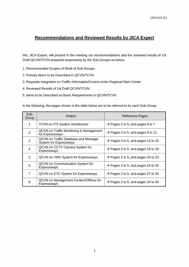
Recommendations and Reviewed Results by JICA Expert
We, JICA Expert, will present in the meeting our recommendations and the reviewed results of 1st
Draft QCVN/TCVN prepared respectively by the Sub-Groups as below.
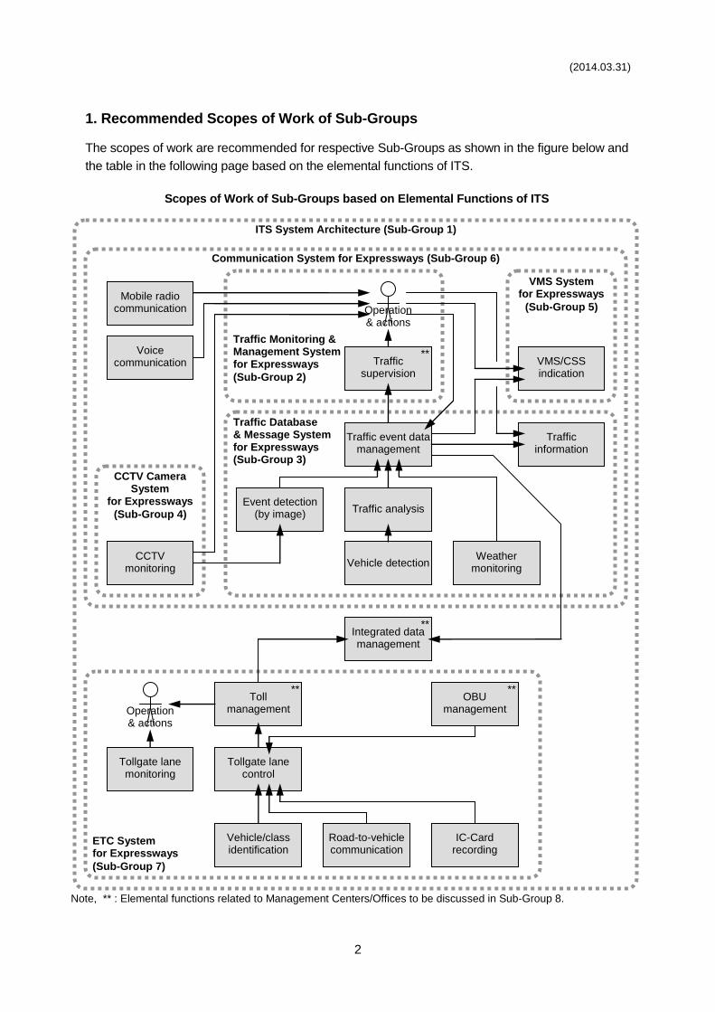
1. Recommended Scopes of Work of Sub-Groups
2. Primary Items to be Described in QCVN/TCVN
3. Requisite Integration on Traffic Information/Control under Regional Main Center
4. Reviewed Results of 1st Draft QCVN/TCVN
5. Items to be Described as Basic Requirements in QCVN/TCVN.
In the following, the pages shown in the table below are to be referred to by each Sub-Group.
Sub-Group
Output Reference Pages
1 TCVN on ITS System Architecture Pages 2 to 5, and pages 6 to 7
2 QCVN on Traffic Monitoring & Management for Expressways
Pages 2 to 5, and pages 8 to 11
3 QCVN on Traffic Database and Message System for Expressways
Pages 2 to 5, and pages 12 to 15
4 QCVN on CCTV Camera System for Expressways
Pages 2 to 5, and pages 16 to 19
5 QCVN on VMS System for Expressways Pages 2 to 5, and pages 20 to 23
6 QCVN on Communication System for Expressways
Pages 2 to 5, and pages 24 to 26
7 QCVN on ETC System for Expressways Pages 2 to 5, and pages 27 to 33
8 QCVN on Management Centers/Offices for Expressways
Pages 2 to 5, and pages 34 to 40
(2014.03.31)
2
1. Recommended Scopes of Work of Sub-Groups
The scopes of work are recommended for respective Sub-Groups as shown in the figure below and
the table in the following page based on the elemental functions of ITS.
Scopes of Work of Sub-Groups based on Elemental Functions of ITS
Voice communication
CCTV monitoring
Event detection (by image)
Vehicle detection
Traffic analysis
Weather monitoring
Traffic event data management
Traffic supervision
VMS/CSS indication
Mobile radio communication
Traffic information
Traffic Monitoring & Management System for Expressways
(Sub-Group 2)
Traffic Database & Message System for Expressways (Sub-Group 3)
CCTV Camera System
for Expressways
(Sub-Group 4)
VMS System for Expressways
(Sub-Group 5)
Communication System for Expressways (Sub-Group 6)
ITS System Architecture (Sub-Group 1)
**
Operation & actions
Tollgate lane monitoring
Vehicle/class identification
Tollgate lane control
Road-to-vehicle communication
IC-Card recording
Toll management
OBU management
Integrated data management
ETC System for Expressways
(Sub-Group 7)
** **
**
Note, ** : Elemental functions related to Management Centers/Offices to be discussed in Sub-Group 8.
Operation & actions
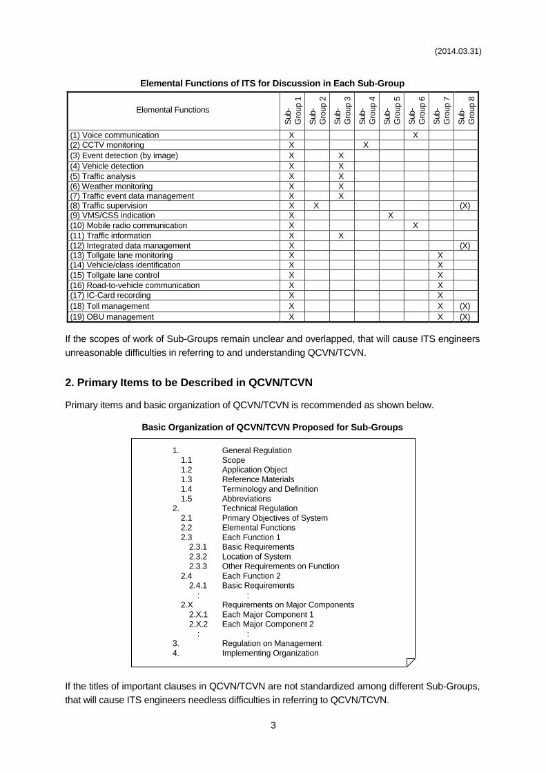
(2014.03.31)
3
Elemental Functions of ITS for Discussion in Each Sub-Group
Elemental Functions
Sub-
Gro
up 1
Sub-
Gro
up 2
Sub-
Gro
up 3
Sub-
Gro
up 4
Sub-
Gro
up 5
Sub-
Gro
up 6
Sub-
Gro
up 7
Sub-
Gro
up 8
(1) Voice communication X X
(2) CCTV monitoring X X
(3) Event detection (by image) X X
(4) Vehicle detection X X
(5) Traffic analysis X X
(6) Weather monitoring X X
(7) Traffic event data management X X (8) Traffic supervision X X (X)
(9) VMS/CSS indication X X
(10) Mobile radio communication X X
(11) Traffic information X X
(12) Integrated data management X (X) (13) Tollgate lane monitoring X X
(14) Vehicle/class identification X X
(15) Tollgate lane control X X
(16) Road-to-vehicle communication X X
(17) IC-Card recording X X
(18) Toll management X X (X)
(19) OBU management X X (X)
If the scopes of work of Sub-Groups remain unclear and overlapped, that will cause ITS engineers
unreasonable difficulties in referring to and understanding QCVN/TCVN.
2. Primary Items to be Described in QCVN/TCVN
Primary items and basic organization of QCVN/TCVN is recommended as shown below.
Basic Organization of QCVN/TCVN Proposed for Sub-Groups
1. General Regulation
1.1 Scope 1.2 Application Object
1.3 Reference Materials 1.4 Terminology and Definition
1.5 Abbreviations 2. Technical Regulation
2.1 Primary Objectives of System 2.2 Elemental Functions
2.3 Each Function 1 2.3.1 Basic Requirements
2.3.2 Location of System 2.3.3 Other Requirements on Function
2.4 Each Function 2 2.4.1 Basic Requirements
: : 2.X Requirements on Major Components
2.X.1 Each Major Component 1 2.X.2 Each Major Component 2
: : 3. Regulation on Management
4. Implementing Organization
If the titles of important clauses in QCVN/TCVN are not standardized among different Sub-Groups,
that will cause ITS engineers needless difficulties in referring to QCVN/TCVN.
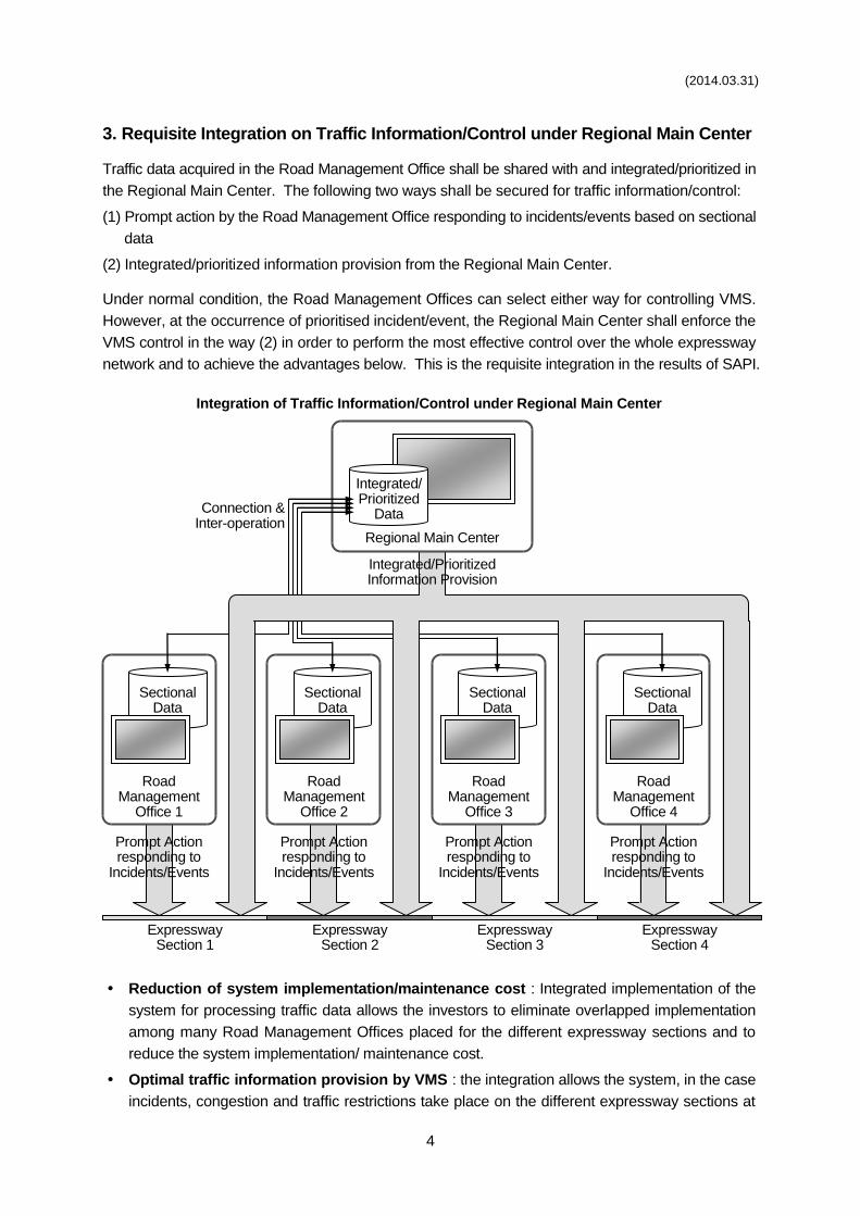
(2014.03.31)
4
3. Requisite Integration on Traffic Information/Control under Regional Main Center
Traffic data acquired in the Road Management Office shall be shared with and integrated/prioritized in
the Regional Main Center. The following two ways shall be secured for traffic information/control:
(1) Prompt action by the Road Management Office responding to incidents/events based on sectional
data
(2) Integrated/prioritized information provision from the Regional Main Center.
Under normal condition, the Road Management Offices can select either way for controlling VMS.
However, at the occurrence of prioritised incident/event, the Regional Main Center shall enforce the
VMS control in the way (2) in order to perform the most effective control over the whole expressway
network and to achieve the advantages below. This is the requisite integration in the results of SAPI.
Integration of Traffic Information/Control under Regional Main Center
Reduction of system implementation/maintenance cost : Integrated implementation of the
system for processing traffic data allows the investors to eliminate overlapped implementation
among many Road Management Offices placed for the different expressway sections and to
reduce the system implementation/ maintenance cost.
Optimal traffic information provision by VMS : the integration allows the system, in the case
incidents, congestion and traffic restrictions take place on the different expressway sections at
Expressway Section 1
Expressway Section 2
Expressway Section 3
Expressway Section 4
Road Management
Office 1
Road Management
Office 2
Road Management
Office 3
Road Management
Office 4
Integrated/Prioritized Information Provision
Prompt Action responding to
Incidents/Events
Connection & Inter-operation
Regional Main Center
Integrated/ Prioritized
Data
Sectional Data
Sectional Data
Sectional Data
Sectional Data
Prompt Action responding to
Incidents/Events
Prompt Action responding to
Incidents/Events
Prompt Action responding to
Incidents/Events
(2014.03.31)
5
the same time, to define priority of each event based on its relative location to the installed
point of VMS and traffic volume and to indicate the optimal information on each VMS.
Reduction of operation cost by saving man-power : 24-hour automatic operation of the optimal
information provision aforementioned allows the Road Management Office Staff to concentrate on
clearing incidents or enforcing traffic restrictions, and to operate at low cost by saving man-power.
Realization of system back-up : In the case a system for VMS control has been installed in a
Road Management Office, it can be utilized for system back-up for the case of system down in
the Regional Main Center and other unusual cases.
4. Reviewed Results of 1st Draft QCVN/TCVN
JICA Expert received the following six 1st Draft QCVNs prepared by the respective Sub-Groups:
Sub-Group 2: QCVN on Traffic Monitoring & Management for Expressways
Sub-Group 4: QCVN on CCTV Camera System for Expressways
Sub-Group 5: QCVN on VMS System for Expressways
Sub-Group 6: QCVN on Communication System for Expressways
Sub-Group 7: QCVN on ETC System for Expressways
Sub-Group 8: QCVN on Management Centers/Offices for Expressways.
These 1st draft QCVNs were reviewed in accordance with the system policies which were concluded
as the major opinion in the 17 times Working Groups with attendance of the persons responsible in
MOT, VEC, DRVN and other organizations and the Study Team Members for the following three
JICA Studies:
Study for ITS Master Plan Development in VITRANSS2
Study for Supporting ITS Standards & Operation Plan Development in Vietnam
Study of Special Assistance for Project Implementation (SAPI) for ITS Integration Project on
New National Highway No.3 & Northern Area of Vietnam.
The reviewed results by the JICA Expert are to be shown in the tables later being classified into the
following five groups:
Definitions inconsistent with SAPI
Definitions in the scope of other QCVN/TCVN
Definitions improper for QCVN
Dropout of essential contents
Not standardized title of clause.
The items of 1st Draft QCVN grouped as “Definitions inconsistent with SAPI” shall be revised in
accordance with the system policies in SAPI, which is to be applied to the ITS Integrated Project, or
shall be removed from the Draft. The items grouped as “Definitions in the scope of other QCVN” shall
be revised or removed as well. That are necessary to resolve the disagreement with JICA Expert.
5. Items to be Described as Basic Requirements in QCVN/TCVN
Finally in the following pages, recommendations were made on the items to be described in QCVN/
TCVN respectively for eight Sub-Groups.
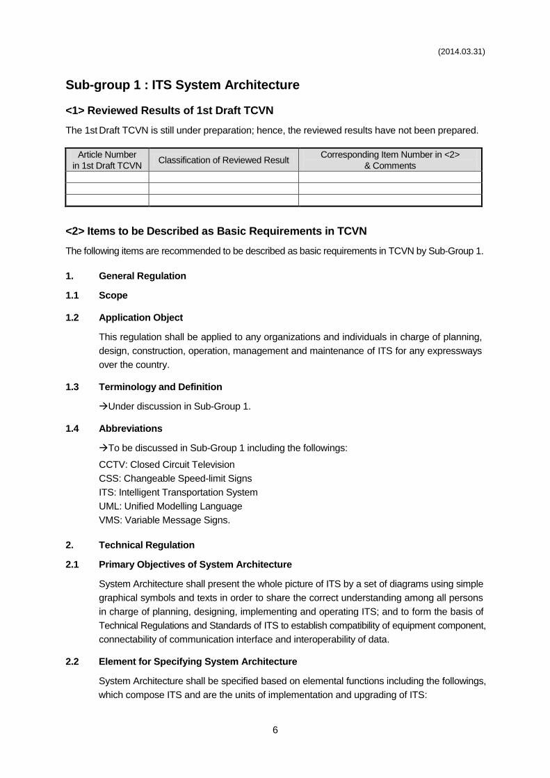
(2014.03.31)
6
Sub-group 1 : ITS System Architecture
<1> Reviewed Results of 1st Draft TCVN
The 1st Draft TCVN is still under preparation; hence, the reviewed results have not been prepared.
Article Number
in 1st Draft TCVN Classification of Reviewed Result
Corresponding Item Number in <2>
& Comments
<2> Items to be Described as Basic Requirements in TCVN
The following items are recommended to be described as basic requirements in TCVN by Sub-Group 1.
1. General Regulation
1.1 Scope
1.2 Application Object
This regulation shall be applied to any organizations and individuals in charge of planning,
design, construction, operation, management and maintenance of ITS for any expressways
over the country.
1.3 Terminology and Definition
Under discussion in Sub-Group 1.
1.4 Abbreviations
To be discussed in Sub-Group 1 including the followings:
CCTV: Closed Circuit Television
CSS: Changeable Speed-limit Signs
ITS: Intelligent Transportation System
UML: Unified Modelling Language
VMS: Variable Message Signs.
2. Technical Regulation
2.1 Primary Objectives of System Architecture
System Architecture shall present the whole picture of ITS by a set of diagrams using simple
graphical symbols and texts in order to share the correct understanding among all persons
in charge of planning, designing, implementing and operating ITS; and to form the basis of
Technical Regulations and Standards of ITS to establish compatibility of equipment component,
connectability of communication interface and interoperability of data.
2.2 Element for Specifying System Architecture
System Architecture shall be specified based on elemental functions including the followings,
which compose ITS and are the units of implementation and upgrading of ITS:
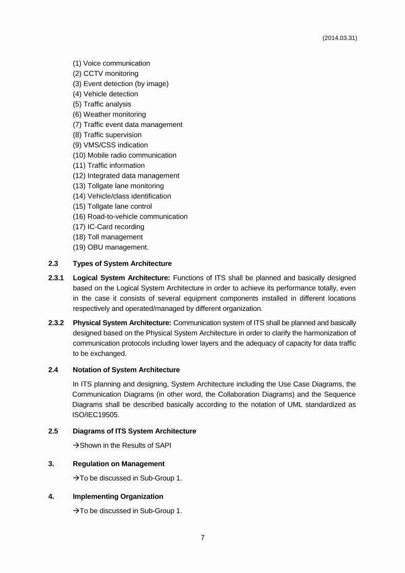
(2014.03.31)
7
(1) Voice communication
(2) CCTV monitoring
(3) Event detection (by image)
(4) Vehicle detection
(5) Traffic analysis
(6) Weather monitoring
(7) Traffic event data management
(8) Traffic supervision
(9) VMS/CSS indication
(10) Mobile radio communication
(11) Traffic information
(12) Integrated data management
(13) Tollgate lane monitoring
(14) Vehicle/class identification
(15) Tollgate lane control
(16) Road-to-vehicle communication
(17) IC-Card recording
(18) Toll management
(19) OBU management.
2.3 Types of System Architecture
2.3.1 Logical System Architecture: Functions of ITS shall be planned and basically designed
based on the Logical System Architecture in order to achieve its performance totally, even
in the case it consists of several equipment components installed in different locations
respectively and operated/managed by different organization.
2.3.2 Physical System Architecture: Communication system of ITS shall be planned and basically
designed based on the Physical System Architecture in order to clarify the harmonization of
communication protocols including lower layers and the adequacy of capacity for data traffic
to be exchanged.
2.4 Notation of System Architecture
In ITS planning and designing, System Architecture including the Use Case Diagrams, the
Communication Diagrams (in other word, the Collaboration Diagrams) and the Sequence
Diagrams shall be described basically according to the notation of UML standardized as
ISO/IEC19505.
2.5 Diagrams of ITS System Architecture
Shown in the Results of SAPI
3. Regulation on Management
To be discussed in Sub-Group 1.
4. Implementing Organization
To be discussed in Sub-Group 1.
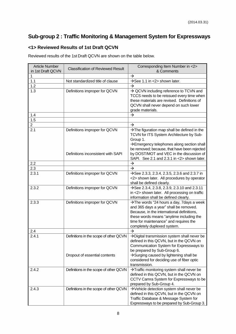
(2014.03.31)
8
Sub-group 2 : Traffic Monitoring & Management System for Expressways
<1> Reviewed Results of 1st Draft QCVN
Reviewed results of the 1st Draft QCVN are shown on the table below.
Article Number
in 1st Draft QCVN Classification of Reviewed Result
Corresponding Item Number in <2>
& Comments
1
1.1 Not standardized title of clause See 1.1 in <2> shown later.
1.2
1.3 Definitions improper for QCVN QCVN including reference to TCVN and
TCCS needs to be reissued every time when
these materials are revised. Definitions of
QCVN shall never depend on such lower
grade materials.
1.4
1.5
2
2.1 Definitions improper for QCVN
Definitions inconsistent with SAPI
The figuration map shall be defined in the
TCVN for ITS System Architecture by Sub-
Group 1.
Emergency telephones along section shall
be removed; because, that have been rejected
by DOST/MOT and VEC in the discussion of
SAPI. See 2.1 and 2.3.1 in <2> shown later.
2.2
2.3
2.3.1 Definitions improper for QCVN See 2.3.3, 2.3.4, 2.3.5, 2.3.6 and 2.3.7 in
<2> shown later. All procedures by operator
shall be defined clearly.
2.3.2 Definitions improper for QCVN See 2.3.4, 2.3.8, 2.3.9, 2.3.10 and 2.3.11
in <2> shown later. All processing on traffic
information shall be defined clearly.
2.3.3 Definitions improper for QCVN The words “24 hours a day, 7days a week
and 365 days a year” shall be removed.
Because, in the international definitions,
these words means “anytime including the
time for maintenance” and requires the
completely duplexed system.
2.4
2.4.1 Definitions in the scope of other QCVN
Dropout of essential contents
Digital transmission system shall never be
defined in this QCVN, but in the QCVN on
Communication System for Expressways to
be prepared by Sub-Group 6.
Surging caused by lightening shall be
considered for deciding use of fiber optic
transmission.
2.4.2 Definitions in the scope of other QCVN Traffic monitoring system shall never be
defined in this QCVN, but in the QCVN on
CCTV Camra System for Expressways to be
prepared by Sub-Group 4.
2.4.3 Definitions in the scope of other QCVN
Vehicle detection system shall never be
defined in this QCVN, but in the QCVN on
Traffic Database & Message System for
Expressways to be prepared by Sub-Group 3.
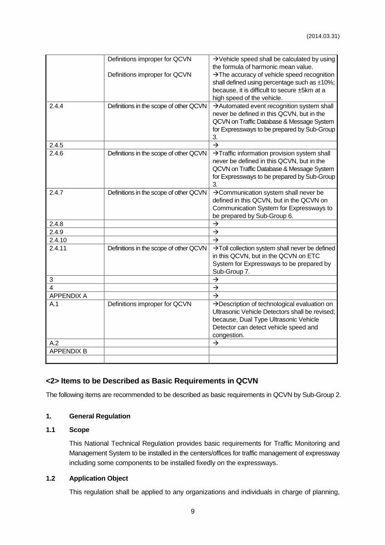
(2014.03.31)
9
Definitions improper for QCVN
Definitions improper for QCVN
Vehicle speed shall be calculated by using
the formula of harmonic mean value.
The accuracy of vehicle speed recognition
shall defined using percentage such as ±10%;
because, it is difficult to secure ±5km at a
high speed of the vehicle.
2.4.4 Definitions in the scope of other QCVN Automated event recognition system shall
never be defined in this QCVN, but in the
QCVN on Traffic Database & Message System
for Expressways to be prepared by Sub-Group
3.
2.4.5
2.4.6 Definitions in the scope of other QCVN Traffic information provision system shall
never be defined in this QCVN, but in the
QCVN on Traffic Database & Message System
for Expressways to be prepared by Sub-Group
3.
2.4.7 Definitions in the scope of other QCVN Communication system shall never be
defined in this QCVN, but in the QCVN on
Communication System for Expressways to
be prepared by Sub-Group 6.
2.4.8
2.4.9
2.4.10
2.4.11 Definitions in the scope of other QCVN Toll collection system shall never be defined
in this QCVN, but in the QCVN on ETC
System for Expressways to be prepared by
Sub-Group 7.
3
4
APPENDIX A
A.1 Definitions improper for QCVN Description of technological evaluation on
Ultrasonic Vehicle Detectors shall be revised;
because, Dual Type Ultrasonic Vehicle
Detector can detect vehicle speed and
congestion.
A.2
APPENDIX B
<2> Items to be Described as Basic Requirements in QCVN
The following items are recommended to be described as basic requirements in QCVN by Sub-Group 2.
1. General Regulation
1.1 Scope
This National Technical Regulation provides basic requirements for Traffic Monitoring and
Management System to be installed in the centers/offices for traffic management of expressway
including some components to be installed fixedly on the expressways.
1.2 Application Object
This regulation shall be applied to any organizations and individuals in charge of planning,
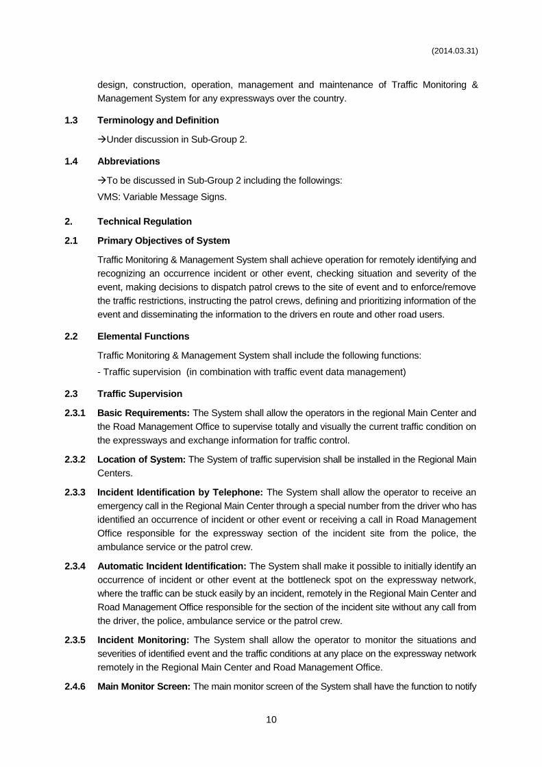
(2014.03.31)
10
design, construction, operation, management and maintenance of Traffic Monitoring &
Management System for any expressways over the country.
1.3 Terminology and Definition
Under discussion in Sub-Group 2.
1.4 Abbreviations
To be discussed in Sub-Group 2 including the followings:
VMS: Variable Message Signs.
2. Technical Regulation
2.1 Primary Objectives of System
Traffic Monitoring & Management System shall achieve operation for remotely identifying and
recognizing an occurrence incident or other event, checking situation and severity of the
event, making decisions to dispatch patrol crews to the site of event and to enforce/remove
the traffic restrictions, instructing the patrol crews, defining and prioritizing information of the
event and disseminating the information to the drivers en route and other road users.
2.2 Elemental Functions
Traffic Monitoring & Management System shall include the following functions:
- Traffic supervision (in combination with traffic event data management)
2.3 Traffic Supervision
2.3.1 Basic Requirements: The System shall allow the operators in the regional Main Center and
the Road Management Office to supervise totally and visually the current traffic condition on
the expressways and exchange information for traffic control.
2.3.2 Location of System: The System of traffic supervision shall be installed in the Regional Main
Centers.
2.3.3 Incident Identification by Telephone: The System shall allow the operator to receive an
emergency call in the Regional Main Center through a special number from the driver who has
identified an occurrence of incident or other event or receiving a call in Road Management
Office responsible for the expressway section of the incident site from the police, the
ambulance service or the patrol crew.
2.3.4 Automatic Incident Identification: The System shall make it possible to initially identify an
occurrence of incident or other event at the bottleneck spot on the expressway network,
where the traffic can be stuck easily by an incident, remotely in the Regional Main Center and
Road Management Office responsible for the section of the incident site without any call from
the driver, the police, ambulance service or the patrol crew.
2.3.5 Incident Monitoring: The System shall allow the operator to monitor the situations and
severities of identified event and the traffic conditions at any place on the expressway network
remotely in the Regional Main Center and Road Management Office.
2.4.6 Main Monitor Screen: The main monitor screen of the System shall have the function to notify
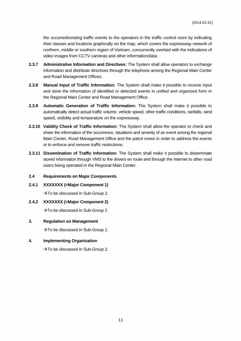
(2014.03.31)
11
the occurred/existing traffic events to the operators in the traffic control room by indicating
their classes and locations graphically on the map, which covers the expressway network of
northern, middle or southern region of Vietnam, concurrently overlaid with the indications of
video images from CCTV cameras and other information/data.
2.3.7 Administrative Information and Directives: The System shall allow operators to exchange
information and distribute directives through the telephone among the Regional Main Center
and Road Management Offices.
2.3.8 Manual Input of Traffic Information: The System shall make it possible to receive input
and store the information of identified or detected events in unified and organized form in
the Regional Main Center and Road Management Office.
2.3.9 Automatic Generation of Traffic Information: The System shall make it possible to
automatically detect actual traffic volume, vehicle speed, other traffic conditions, rainfalls, wind
speed, visibility and temperature on the expressway.
2.3.10 Validity Check of Traffic Information: The System shall allow the operator to check and
share the information of the occurrence, situations and severity of an event among the regional
Main Center, Road Management Office and the patrol crews in order to address the events
or to enforce and remove traffic restrictions.
2.3.11 Dissemination of Traffic Information: The System shall make it possible to disseminate
stored information through VMS to the drivers en route and through the Internet to other road
users being operated in the Regional Main Center.
2.4 Requirements on Major Components
2.4.1 XXXXXXX (=Major Component 1)
To be discussed in Sub-Group 2.
2.4.2 XXXXXXX (=Major Component 2)
To be discussed in Sub-Group 2.
3. Regulation on Management
To be discussed in Sub-Group 2.
4. Implementing Organization
To be discussed in Sub-Group 2.
(2014.03.31)
12
Sub-group 3 : Traffic Database & Message System for Expressways
<1> Reviewed Results of 1st Draft QCVN
The 1st Draft QCVN is still under preparation; hence, the reviewed results have not been prepared.
Article Number
in 1st Draft QCVN Classification of Reviewed Result
Corresponding Item Number in <2>
& Comments
<2> Items to be Described as Basic Requirements in QCVN
The following items are recommended to be described as basic requirements in QCVN by Sub-Group 3.
1. General Regulation
1.1 Scope
This National Technical Regulation provides basic requirements for Traffic Database &
Message System to be installed in the centers/offices for traffic management of expressway
including some components to be installed fixedly on the expressways.
1.2 Application Object
This regulation shall be applied to any organizations and individuals in charge of planning,
design, construction, operation, management and maintenance of Traffic Database & Message
System for any expressways over the country.
1.3 Terminology and Definition
Under discussion in Sub-Group 3.
1.4 Abbreviations
To be discussed in Sub-Group 3 including the followings:
CCTV: Closed Circuit Television
IP: Internet Protocol
TCP: Transmission Control Protocol
VMS: Variable Message Signs.
2. Technical Regulation
2.1 Primary Objectives of System
Traffic Database & Message System shall achieve identification of incidents, other events,
traffic conditions and weather conditions on the expressway; generation of data in a unified/
integrated form for sharing it among the Regional Main Center, relevant Road Management
Offices and patrol crews and for disseminating it to the drivers en route and other road users.
2.2 Elemental Functions
Traffic Database and Message System shall include the following functions:
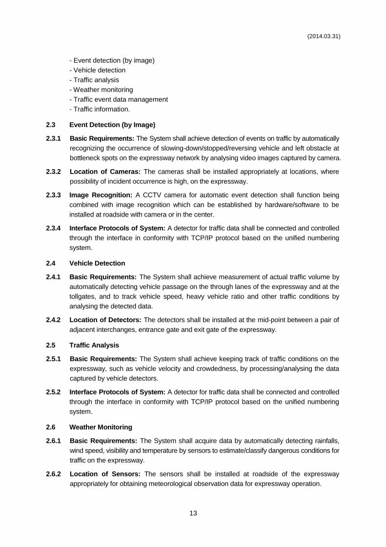
(2014.03.31)
13
- Event detection (by image)
- Vehicle detection
- Traffic analysis
- Weather monitoring
- Traffic event data management
- Traffic information.
2.3 Event Detection (by Image)
2.3.1 Basic Requirements: The System shall achieve detection of events on traffic by automatically
recognizing the occurrence of slowing-down/stopped/reversing vehicle and left obstacle at
bottleneck spots on the expressway network by analysing video images captured by camera.
2.3.2 Location of Cameras: The cameras shall be installed appropriately at locations, where
possibility of incident occurrence is high, on the expressway.
2.3.3 Image Recognition: A CCTV camera for automatic event detection shall function being
combined with image recognition which can be established by hardware/software to be
installed at roadside with camera or in the center.
2.3.4 Interface Protocols of System: A detector for traffic data shall be connected and controlled
through the interface in conformity with TCP/IP protocol based on the unified numbering
system.
2.4 Vehicle Detection
2.4.1 Basic Requirements: The System shall achieve measurement of actual traffic volume by
automatically detecting vehicle passage on the through lanes of the expressway and at the
tollgates, and to track vehicle speed, heavy vehicle ratio and other traffic conditions by
analysing the detected data.
2.4.2 Location of Detectors: The detectors shall be installed at the mid-point between a pair of
adjacent interchanges, entrance gate and exit gate of the expressway.
2.5 Traffic Analysis
2.5.1 Basic Requirements: The System shall achieve keeping track of traffic conditions on the
expressway, such as vehicle velocity and crowdedness, by processing/analysing the data
captured by vehicle detectors.
2.5.2 Interface Protocols of System: A detector for traffic data shall be connected and controlled
through the interface in conformity with TCP/IP protocol based on the unified numbering
system.
2.6 Weather Monitoring
2.6.1 Basic Requirements: The System shall acquire data by automatically detecting rainfalls,
wind speed, visibility and temperature by sensors to estimate/classify dangerous conditions for
traffic on the expressway.
2.6.2 Location of Sensors: The sensors shall be installed at roadside of the expressway
appropriately for obtaining meteorological observation data for expressway operation.
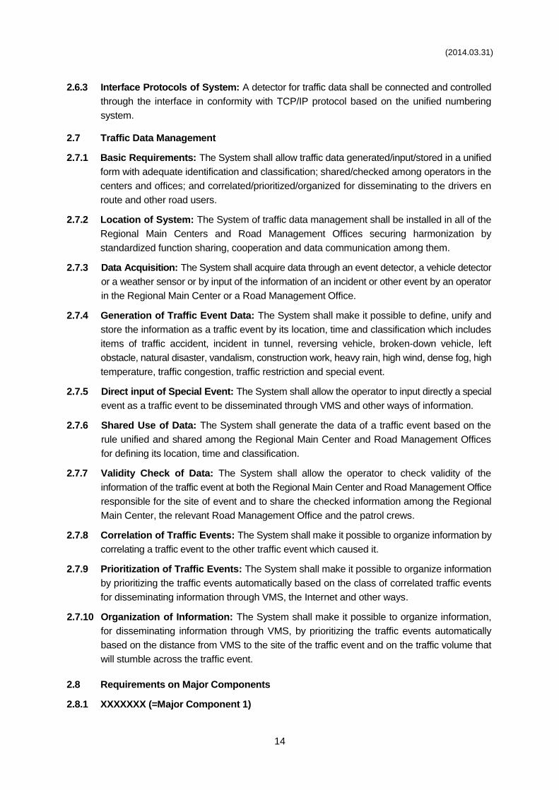
(2014.03.31)
14
2.6.3 Interface Protocols of System: A detector for traffic data shall be connected and controlled
through the interface in conformity with TCP/IP protocol based on the unified numbering
system.
2.7 Traffic Data Management
2.7.1 Basic Requirements: The System shall allow traffic data generated/input/stored in a unified
form with adequate identification and classification; shared/checked among operators in the
centers and offices; and correlated/prioritized/organized for disseminating to the drivers en
route and other road users.
2.7.2 Location of System: The System of traffic data management shall be installed in all of the
Regional Main Centers and Road Management Offices securing harmonization by
standardized function sharing, cooperation and data communication among them.
2.7.3 Data Acquisition: The System shall acquire data through an event detector, a vehicle detector
or a weather sensor or by input of the information of an incident or other event by an operator
in the Regional Main Center or a Road Management Office.
2.7.4 Generation of Traffic Event Data: The System shall make it possible to define, unify and
store the information as a traffic event by its location, time and classification which includes
items of traffic accident, incident in tunnel, reversing vehicle, broken-down vehicle, left
obstacle, natural disaster, vandalism, construction work, heavy rain, high wind, dense fog, high
temperature, traffic congestion, traffic restriction and special event.
2.7.5 Direct input of Special Event: The System shall allow the operator to input directly a special
event as a traffic event to be disseminated through VMS and other ways of information.
2.7.6 Shared Use of Data: The System shall generate the data of a traffic event based on the
rule unified and shared among the Regional Main Center and Road Management Offices
for defining its location, time and classification.
2.7.7 Validity Check of Data: The System shall allow the operator to check validity of the
information of the traffic event at both the Regional Main Center and Road Management Office
responsible for the site of event and to share the checked information among the Regional
Main Center, the relevant Road Management Office and the patrol crews.
2.7.8 Correlation of Traffic Events: The System shall make it possible to organize information by
correlating a traffic event to the other traffic event which caused it.
2.7.9 Prioritization of Traffic Events: The System shall make it possible to organize information
by prioritizing the traffic events automatically based on the class of correlated traffic events
for disseminating information through VMS, the Internet and other ways.
2.7.10 Organization of Information: The System shall make it possible to organize information,
for disseminating information through VMS, by prioritizing the traffic events automatically
based on the distance from VMS to the site of the traffic event and on the traffic volume that
will stumble across the traffic event.
2.8 Requirements on Major Components
2.8.1 XXXXXXX (=Major Component 1)

(2014.03.31)
15
To be discussed in Sub-Group 3.
2.8.2 XXXXXXX (=Major Component 2)
To be discussed in Sub-Group 3.
3. Regulation on Management
To be discussed in Sub-Group 3.
4. Implementing Organization
To be discussed in Sub-Group 3.
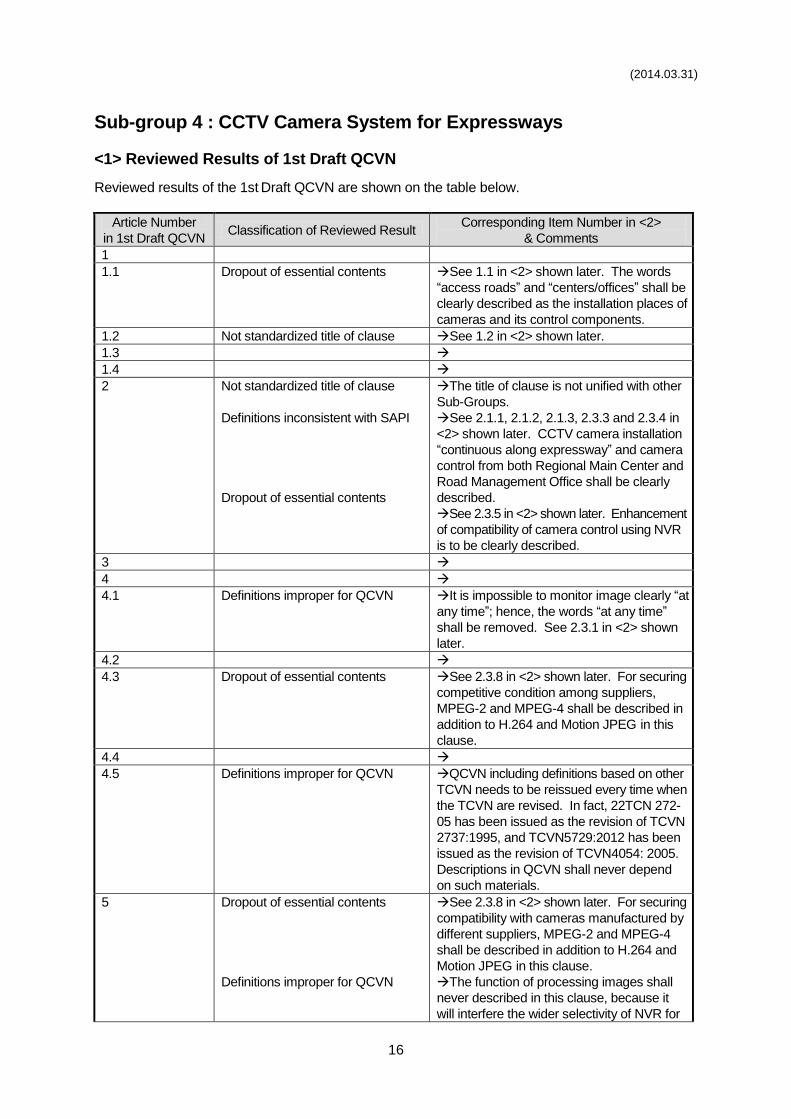
(2014.03.31)
16
Sub-group 4 : CCTV Camera System for Expressways
<1> Reviewed Results of 1st Draft QCVN
Reviewed results of the 1st Draft QCVN are shown on the table below.
Article Number
in 1st Draft QCVN Classification of Reviewed Result
Corresponding Item Number in <2>
& Comments
1
1.1 Dropout of essential contents See 1.1 in <2> shown later. The words
“access roads” and “centers/offices” shall be
clearly described as the installation places of
cameras and its control components.
1.2 Not standardized title of clause See 1.2 in <2> shown later.
1.3
1.4
2 Not standardized title of clause
Definitions inconsistent with SAPI
Dropout of essential contents
The title of clause is not unified with other
Sub-Groups.
See 2.1.1, 2.1.2, 2.1.3, 2.3.3 and 2.3.4 in
<2> shown later. CCTV camera installation
“continuous along expressway” and camera
control from both Regional Main Center and
Road Management Office shall be clearly
described.
See 2.3.5 in <2> shown later. Enhancement
of compatibility of camera control using NVR
is to be clearly described.
3
4
4.1 Definitions improper for QCVN It is impossible to monitor image clearly “at
any time”; hence, the words “at any time”
shall be removed. See 2.3.1 in <2> shown
later.
4.2
4.3 Dropout of essential contents See 2.3.8 in <2> shown later. For securing
competitive condition among suppliers,
MPEG-2 and MPEG-4 shall be described in
addition to H.264 and Motion JPEG in this
clause.
4.4
4.5 Definitions improper for QCVN QCVN including definitions based on other
TCVN needs to be reissued every time when
the TCVN are revised. In fact, 22TCN 272-
05 has been issued as the revision of TCVN
2737:1995, and TCVN5729:2012 has been
issued as the revision of TCVN4054: 2005.
Descriptions in QCVN shall never depend
on such materials.
5 Dropout of essential contents
Definitions improper for QCVN
See 2.3.8 in <2> shown later. For securing
compatibility with cameras manufactured by
different suppliers, MPEG-2 and MPEG-4
shall be described in addition to H.264 and
Motion JPEG in this clause.
The function of processing images shall
never described in this clause, because it
will interfere the wider selectivity of NVR for
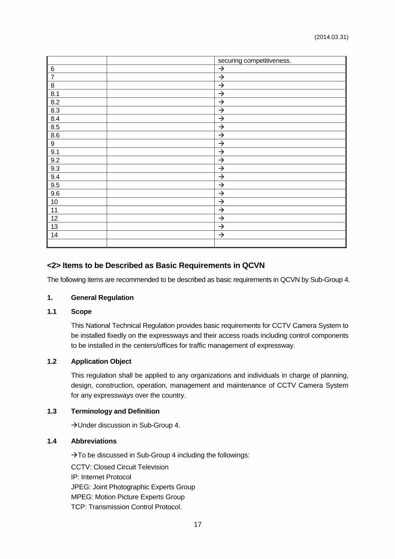
(2014.03.31)
17
securing competitiveness.
6
7
8
8.1
8.2
8.3
8.4
8.5
8.6
9
9.1
9.2
9.3
9.4
9.5
9.6
10
11
12
13
14
<2> Items to be Described as Basic Requirements in QCVN
The following items are recommended to be described as basic requirements in QCVN by Sub-Group 4.
1. General Regulation
1.1 Scope
This National Technical Regulation provides basic requirements for CCTV Camera System to
be installed fixedly on the expressways and their access roads including control components
to be installed in the centers/offices for traffic management of expressway.
1.2 Application Object
This regulation shall be applied to any organizations and individuals in charge of planning,
design, construction, operation, management and maintenance of CCTV Camera System
for any expressways over the country.
1.3 Terminology and Definition
Under discussion in Sub-Group 4.
1.4 Abbreviations
To be discussed in Sub-Group 4 including the followings:
CCTV: Closed Circuit Television
IP: Internet Protocol
JPEG: Joint Photographic Experts Group
MPEG: Motion Picture Experts Group
TCP: Transmission Control Protocol.
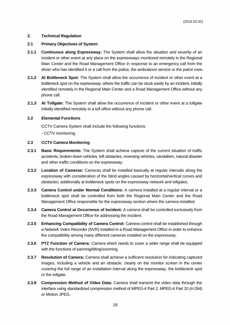
(2014.03.31)
18
2. Technical Regulation
2.1 Primary Objectives of System
2.1.1 Continuous along Expressway: The System shall allow the situation and severity of an
incident or other event at any place on the expressways monitored remotely in the Regional
Main Center and the Road Management Office in response to an emergency call from the
driver who has identified it or a call from the police, the ambulance service or the patrol crew.
2.1.2 At Bottleneck Spot: The System shall allow the occurrence of incident or other event at a
bottleneck spot on the expressway, where the traffic can be stuck easily by an incident, initially
identified remotely in the Regional Main Center and a Road Management Office without any
phone call.
2.1.3 At Tollgate: The System shall allow the occurrence of incident or other event at a tollgate
initially identified remotely in a toll office without any phone call.
2.2 Elemental Functions
CCTV Camera System shall include the following functions:
- CCTV monitoring.
2.3 CCTV Camera Monitoring
2.3.1 Basic Requirements: The System shall achieve capture of the current situation of traffic
accidents, broken-down vehicles, left obstacles, reversing vehicles, vandalism, natural disaster
and other traffic conditions on the expressway.
2.3.2 Location of Cameras: Cameras shall be installed basically at regular intervals along the
expressway with consideration of the blind angles caused by horizontal/vertical curves and
obstacles; additionally at bottleneck spots on the expressway network and tollgates.
2.3.3 Camera Control under Normal Conditions: A camera installed at a regular interval or a
bottleneck spot shall be controlled from both the Regional Main Center and the Road
Management Office responsible for the expressway section where the camera installed.
2.3.4 Camera Control at Occurrence of Incident: A camera shall be controlled exclusively from
the Road Management Office for addressing the incident.
2.3.5 Enhancing Compatibility of Camera Control: Camera control shall be established through
a Network Video Recorder (NVR) installed in a Road Management Office in order to enhance
the compatibility among many different cameras installed on the expressway.
2.3.6 PTZ Function of Camera: Camera which needs to cover a wider range shall be equipped
with the functions of panning/tilting/zooming.
2.3.7 Resolution of Camera: Camera shall achieve a sufficient resolution for indicating captured
images, including a vehicle and an obstacle, clearly on the monitor screen in the center
covering the full range of an installation interval along the expressway, the bottleneck spot
or the tollgate.
2.3.8 Compression Method of Video Data: Camera shall transmit the video data through the
interface using standardized compression method of MPEG-4 Part 2, MPEG-4 Part 10 (H.264)
or Motion JPEG.
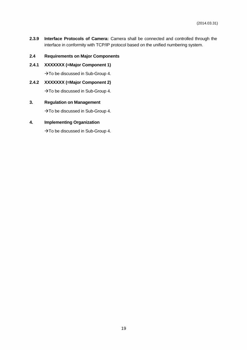
(2014.03.31)
19
2.3.9 Interface Protocols of Camera: Camera shall be connected and controlled through the
interface in conformity with TCP/IP protocol based on the unified numbering system.
2.4 Requirements on Major Components
2.4.1 XXXXXXX (=Major Component 1)
To be discussed in Sub-Group 4.
2.4.2 XXXXXXX (=Major Component 2)
To be discussed in Sub-Group 4.
3. Regulation on Management
To be discussed in Sub-Group 4.
4. Implementing Organization
To be discussed in Sub-Group 4.
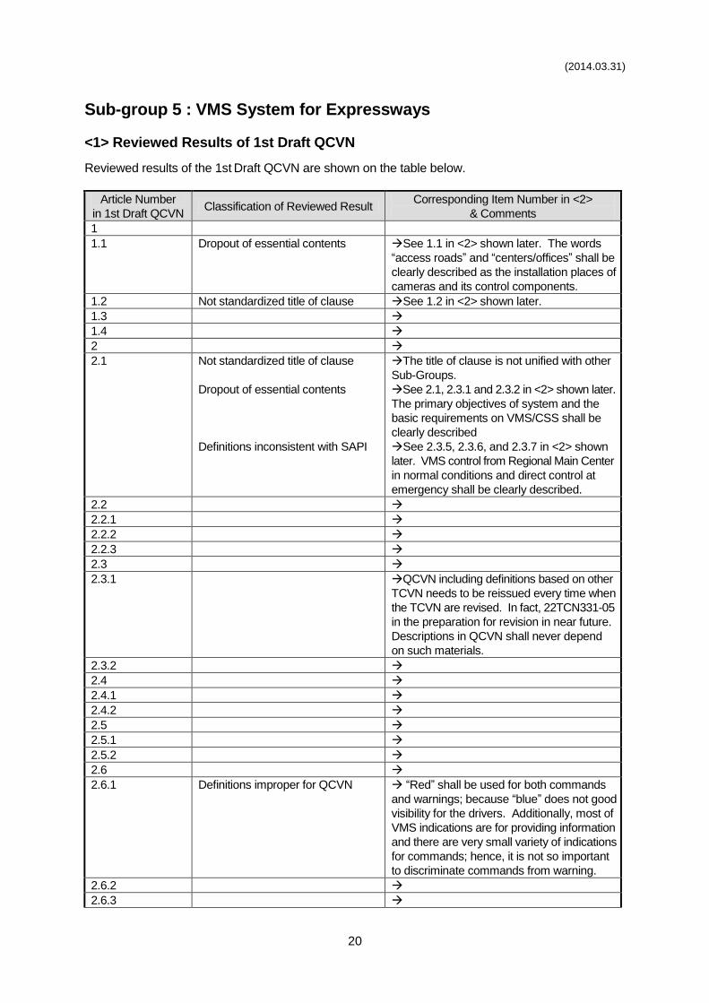
(2014.03.31)
20
Sub-group 5 : VMS System for Expressways
<1> Reviewed Results of 1st Draft QCVN
Reviewed results of the 1st Draft QCVN are shown on the table below.
Article Number
in 1st Draft QCVN Classification of Reviewed Result
Corresponding Item Number in <2>
& Comments
1
1.1 Dropout of essential contents See 1.1 in <2> shown later. The words
“access roads” and “centers/offices” shall be
clearly described as the installation places of
cameras and its control components.
1.2 Not standardized title of clause See 1.2 in <2> shown later.
1.3
1.4
2
2.1 Not standardized title of clause
Dropout of essential contents
Definitions inconsistent with SAPI
The title of clause is not unified with other
Sub-Groups.
See 2.1, 2.3.1 and 2.3.2 in <2> shown later.
The primary objectives of system and the
basic requirements on VMS/CSS shall be
clearly described
See 2.3.5, 2.3.6, and 2.3.7 in <2> shown
later. VMS control from Regional Main Center
in normal conditions and direct control at
emergency shall be clearly described.
2.2
2.2.1
2.2.2
2.2.3
2.3
2.3.1 QCVN including definitions based on other
TCVN needs to be reissued every time when
the TCVN are revised. In fact, 22TCN331-05
in the preparation for revision in near future.
Descriptions in QCVN shall never depend
on such materials.
2.3.2
2.4
2.4.1
2.4.2
2.5
2.5.1
2.5.2
2.6
2.6.1 Definitions improper for QCVN “Red” shall be used for both commands
and warnings; because “blue” does not good
visibility for the drivers. Additionally, most of
VMS indications are for providing information
and there are very small variety of indications
for commands; hence, it is not so important
to discriminate commands from warning.
2.6.2
2.6.3
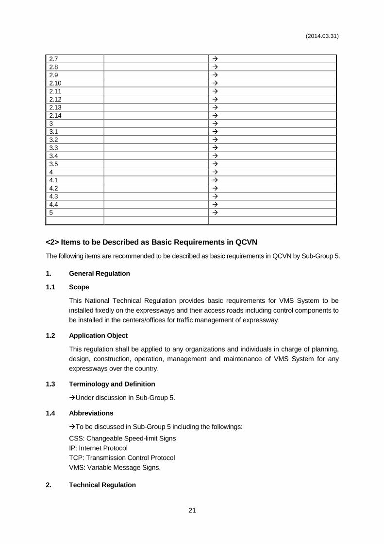
(2014.03.31)
21
2.7
2.8
2.9
2.10
2.11
2.12
2.13
2.14
3
3.1
3.2
3.3
3.4
3.5
4
4.1
4.2
4.3
4.4
5
<2> Items to be Described as Basic Requirements in QCVN
The following items are recommended to be described as basic requirements in QCVN by Sub-Group 5.
1. General Regulation
1.1 Scope
This National Technical Regulation provides basic requirements for VMS System to be
installed fixedly on the expressways and their access roads including control components to
be installed in the centers/offices for traffic management of expressway.
1.2 Application Object
This regulation shall be applied to any organizations and individuals in charge of planning,
design, construction, operation, management and maintenance of VMS System for any
expressways over the country.
1.3 Terminology and Definition
Under discussion in Sub-Group 5.
1.4 Abbreviations
To be discussed in Sub-Group 5 including the followings:
CSS: Changeable Speed-limit Signs
IP: Internet Protocol
TCP: Transmission Control Protocol
VMS: Variable Message Signs.
2. Technical Regulation
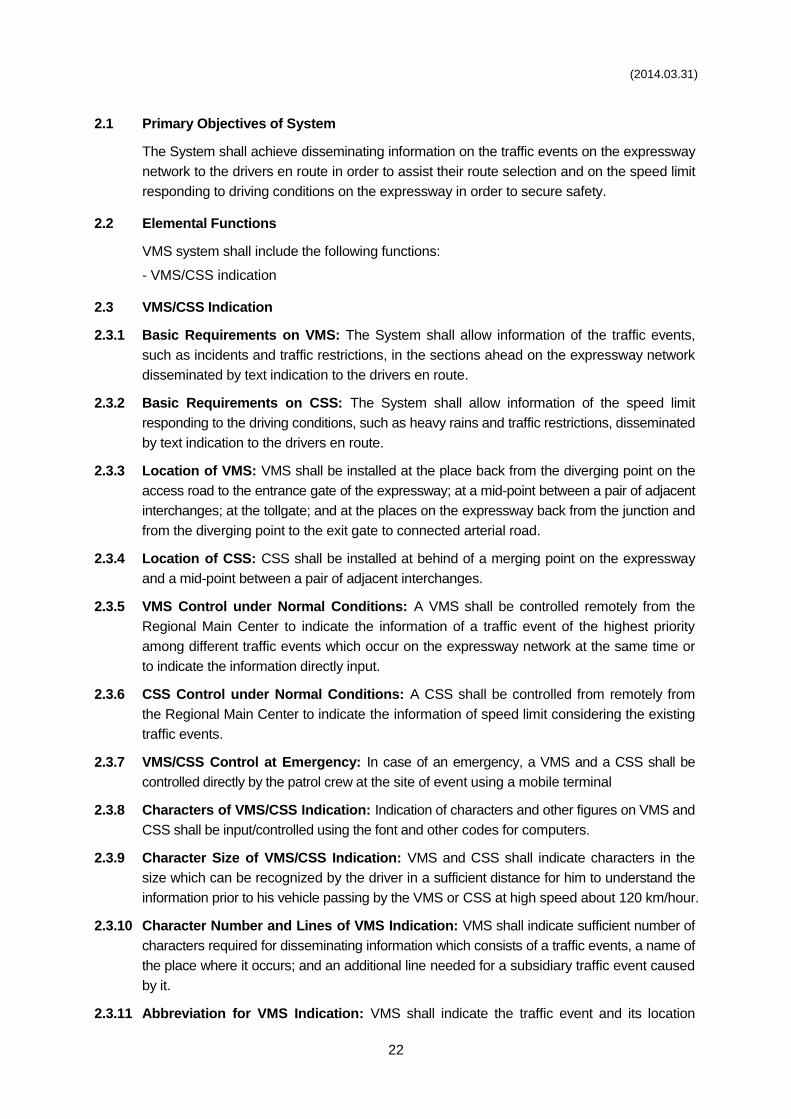
(2014.03.31)
22
2.1 Primary Objectives of System
The System shall achieve disseminating information on the traffic events on the expressway
network to the drivers en route in order to assist their route selection and on the speed limit
responding to driving conditions on the expressway in order to secure safety.
2.2 Elemental Functions
VMS system shall include the following functions:
- VMS/CSS indication
2.3 VMS/CSS Indication
2.3.1 Basic Requirements on VMS: The System shall allow information of the traffic events,
such as incidents and traffic restrictions, in the sections ahead on the expressway network
disseminated by text indication to the drivers en route.
2.3.2 Basic Requirements on CSS: The System shall allow information of the speed limit
responding to the driving conditions, such as heavy rains and traffic restrictions, disseminated
by text indication to the drivers en route.
2.3.3 Location of VMS: VMS shall be installed at the place back from the diverging point on the
access road to the entrance gate of the expressway; at a mid-point between a pair of adjacent
interchanges; at the tollgate; and at the places on the expressway back from the junction and
from the diverging point to the exit gate to connected arterial road.
2.3.4 Location of CSS: CSS shall be installed at behind of a merging point on the expressway
and a mid-point between a pair of adjacent interchanges.
2.3.5 VMS Control under Normal Conditions: A VMS shall be controlled remotely from the
Regional Main Center to indicate the information of a traffic event of the highest priority
among different traffic events which occur on the expressway network at the same time or
to indicate the information directly input.
2.3.6 CSS Control under Normal Conditions: A CSS shall be controlled from remotely from
the Regional Main Center to indicate the information of speed limit considering the existing
traffic events.
2.3.7 VMS/CSS Control at Emergency: In case of an emergency, a VMS and a CSS shall be
controlled directly by the patrol crew at the site of event using a mobile terminal
2.3.8 Characters of VMS/CSS Indication: Indication of characters and other figures on VMS and
CSS shall be input/controlled using the font and other codes for computers.
2.3.9 Character Size of VMS/CSS Indication: VMS and CSS shall indicate characters in the
size which can be recognized by the driver in a sufficient distance for him to understand the
information prior to his vehicle passing by the VMS or CSS at high speed about 120 km/hour.
2.3.10 Character Number and Lines of VMS Indication: VMS shall indicate sufficient number of
characters required for disseminating information which consists of a traffic events, a name of
the place where it occurs; and an additional line needed for a subsidiary traffic event caused
by it.
2.3.11 Abbreviation for VMS Indication: VMS shall indicate the traffic event and its location
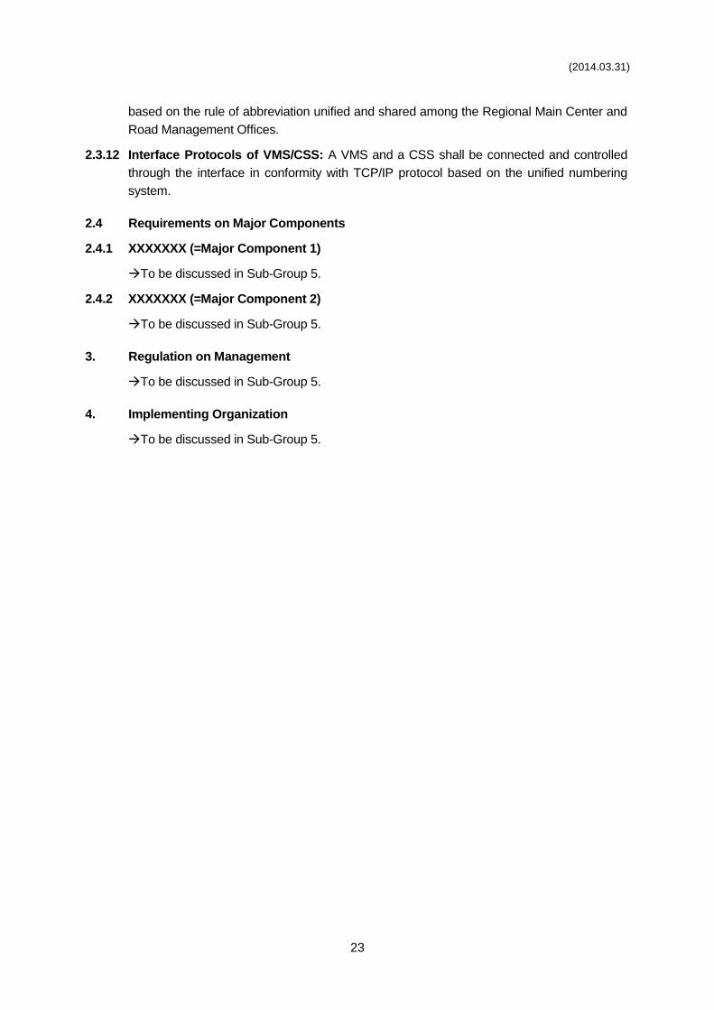
(2014.03.31)
23
based on the rule of abbreviation unified and shared among the Regional Main Center and
Road Management Offices.
2.3.12 Interface Protocols of VMS/CSS: A VMS and a CSS shall be connected and controlled
through the interface in conformity with TCP/IP protocol based on the unified numbering
system.
2.4 Requirements on Major Components
2.4.1 XXXXXXX (=Major Component 1)
To be discussed in Sub-Group 5.
2.4.2 XXXXXXX (=Major Component 2)
To be discussed in Sub-Group 5.
3. Regulation on Management
To be discussed in Sub-Group 5.
4. Implementing Organization
To be discussed in Sub-Group 5.
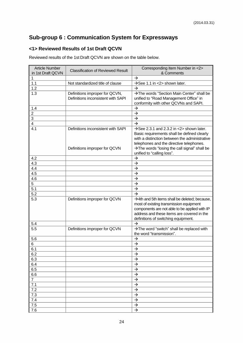
(2014.03.31)
24
Sub-group 6 : Communication System for Expressways
<1> Reviewed Results of 1st Draft QCVN
Reviewed results of the 1st Draft QCVN are shown on the table below.
Article Number
in 1st Draft QCVN Classification of Reviewed Result
Corresponding Item Number in <2>
& Comments
1
1.1 Not standardized title of clause See 1.1 in <2> shown later.
1.2
1.3 Definitions improper for QCVN,
Definitions inconsistent with SAPI
The words “Section Main Center” shall be
unified to “Road Management Office” in
conformity with other QCVNs and SAPI.
1.4
2
3
4
4.1 Definitions inconsistent with SAPI
Definitions improper for QCVN
See 2.3.1 and 2.3.2 in <2> shown later.
Basic requirements shall be defined clearly
with a distinction between the administrative
telephones and the directive telephones.
The words “losing the call signal” shall be
unified to “calling loss”.
4.2
4.3
4.4
4.5
4.6
5
5.1
5.2
5.3 Definitions improper for QCVN 4th and 5th items shall be deleted; because,
most of existing transmission equipment
components are not able to be applied with IP
address and these items are covered in the
definitions of switching equipment.
5.4
5.5 Definitions improper for QCVN The word “switch” shall be replaced with
the word “transmission”.
5.6
6
6.1
6.2
6.3
6.4
6.5
6.6
7
7.1
7.2
7.3
7.4
7.5
7.6
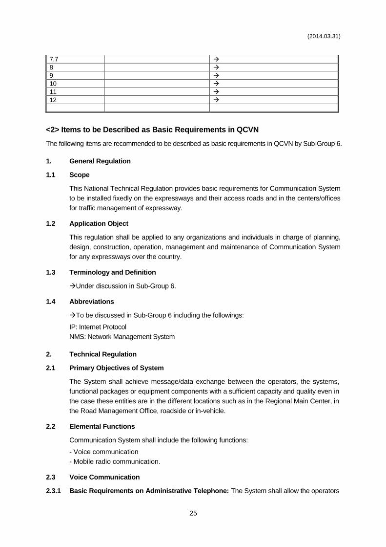
(2014.03.31)
25
7.7
8
9
10
11
12
<2> Items to be Described as Basic Requirements in QCVN
The following items are recommended to be described as basic requirements in QCVN by Sub-Group 6.
1. General Regulation
1.1 Scope
This National Technical Regulation provides basic requirements for Communication System
to be installed fixedly on the expressways and their access roads and in the centers/offices
for traffic management of expressway.
1.2 Application Object
This regulation shall be applied to any organizations and individuals in charge of planning,
design, construction, operation, management and maintenance of Communication System
for any expressways over the country.
1.3 Terminology and Definition
Under discussion in Sub-Group 6.
1.4 Abbreviations
To be discussed in Sub-Group 6 including the followings:
IP: Internet Protocol
NMS: Network Management System
2. Technical Regulation
2.1 Primary Objectives of System
The System shall achieve message/data exchange between the operators, the systems,
functional packages or equipment components with a sufficient capacity and quality even in
the case these entities are in the different locations such as in the Regional Main Center, in
the Road Management Office, roadside or in-vehicle.
2.2 Elemental Functions
Communication System shall include the following functions:
- Voice communication
- Mobile radio communication.
2.3 Voice Communication
2.3.1 Basic Requirements on Administrative Telephone: The System shall allow the operators
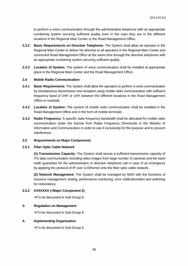
(2014.03.31)
26
to perform a voice communication through the administrative telephone with an appropriate
numbering system securing sufficient quality even in the case they are in the different
locations in the Regional Main Center or the Road Management Office.
2.3.2 Basic Requirements on Directive Telephone: The System shall allow an operator in the
Regional Main Center to deliver his directive to all operators in the Regional Main Center and
concerned Road Management Office at the same time through the directive telephone with
an appropriate numbering system securing sufficient quality.
2.3.3 Location of System: The system of voice communication shall be installed at appropriate
place in the Regional Main Center and the Road Management Office.
2.4 Mobile Radio Communication
2.4.1 Basic Requirements: The System shall allow the operators to perform a voice communication
by simultaneous transmission and reception using mobile radio communication with sufficient
frequency band of VHF or UHF between the different locations in the Road Management
Office or roadside.
2.4.2 Location of System: The system of mobile radio communication shall be installed in the
Road Management Office and in the form of mobile terminals.
2.4.3 Radio Frequency: A specific radio frequency bandwidth shall be allocated for mobile radio
communication under the license from Radio Frequency Directorate in the Ministry of
Information and Communication in order to use it exclusively for the purpose and to prevent
interference.
2.5 Requirements on Major Components
2.5.1 Fiber Optic Cable Network
(1) Transmission Capacity: The System shall secure a sufficient transmission capacity of
ITS data communication including video images from large number of cameras and the band
width guarantee for the administrative or directive telephone call in case of an emergency
by applying the protocol of IP over G-Ethernet onto the fiber optic cable network.
(2) Network Management: The System shall be managed by NMS with the functions of
resource management, testing, performance monitoring, error notification/alert and switching
for redundancy.
2.5.2 XXXXXXX (=Major Component 2)
To be discussed in Sub-Group 6.
3. Regulation on Management
To be discussed in Sub-Group 6.
4. Implementing Organization
To be discussed in Sub-Group 6.
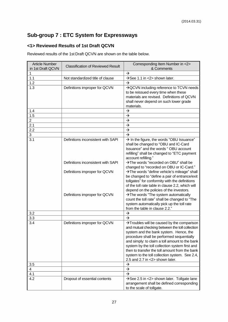
(2014.03.31)
27
Sub-group 7 : ETC System for Expressways
<1> Reviewed Results of 1st Draft QCVN
Reviewed results of the 1st Draft QCVN are shown on the table below.
Article Number
in 1st Draft QCVN Classification of Reviewed Result
Corresponding Item Number in <2>
& Comments
1
1.1 Not standardized title of clause See 1.1 in <2> shown later.
1.2
1.3 Definitions improper for QCVN QCVN including reference to TCVN needs
to be reissued every time when these
materials are revised. Definitions of QCVN
shall never depend on such lower grade
materials.
1.4
1.5
2
2.1
2.2
3
3.1 Definitions inconsistent with SAPI
Definitions inconsistent with SAPI
Definitions improper for QCVN
Definitions improper for QCVN
In the figure, the words “OBU Issuance”
shall be changed to “OBU and IC-Card
Issuance” and the words “ OBU account
refilling” shall be changed to “ETC payment
account refilling.”
The words “recorded on OBU” shall be
changed to “recorded on OBU or IC-Card.”
The words “define vehicle’s mileage” shall
be changed to “define a pair of entrance/exit
tollgates” for conformity with the definitions
of the toll rate table in clause 2.2, which will
depend on the policies of the investors.
The words “The system automatically
count the toll rate” shall be changed to “The
system automatically pick up the toll rate
from the table in clause 2.2.”
3.2
3.3
3.4 Definitions improper for QCVN Troubles will be caused by the comparison
and mutual checking between the toll collection
system and the bank system. Hence, the
procedure shall be performed sequentially
and simply: to claim a toll amount to the bank
system by the toll collection system first and
then to transfer the toll amount from the bank
system to the toll collection system. See 2.4,
2.5 and 2.7 in <2> shown later.
3.5
4
4.1
4.2 Dropout of essential contents See 2.5 in <2> shown later. Tollgate lane
arrangement shall be defined corresponding
to the scale of tollgate.
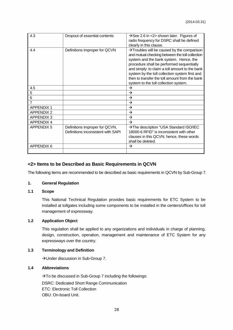
(2014.03.31)
28
4.3 Dropout of essential contents See 2.6 in <2> shown later. Figures of
radio frequency for DSRC shall be defined
clearly in this clause.
4.4 Definitions improper for QCVN Troubles will be caused by the comparison
and mutual checking between the toll collection
system and the bank system. Hence, the
procedure shall be performed sequentially
and simply: to claim a toll amount to the bank
system by the toll collection system first and
then to transfer the toll amount from the bank
system to the toll collection system.
4.5
5
6
7
APPENDIX 1
APPENDIX 2
APPENDIX 3
APPENDIX 4
APPENDIX 5 Definitions improper for QCVN,
Definitions inconsistent with SAPI
The description “USA Standard ISO/IEC
18000-6 RFID” is inconsistent with other
clauses in this QCVN; hence, these words
shall be deleted.
APPENDIX 6
<2> Items to be Described as Basic Requirements in QCVN
The following items are recommended to be described as basic requirements in QCVN by Sub-Group 7.
1. General Regulation
1.1 Scope
This National Technical Regulation provides basic requirements for ETC System to be
installed at tollgates including some components to be installed in the centers/offices for toll
management of expressway.
1.2 Application Object
This regulation shall be applied to any organizations and individuals in charge of planning,
design, construction, operation, management and maintenance of ETC System for any
expressways over the country.
1.3 Terminology and Definition
Under discussion in Sub-Group 7.
1.4 Abbreviations
To be discussed in Sub-Group 7 including the followings:
DSRC: Dedicated Short Range Communication
ETC: Electronic Toll Collection
OBU: On-board Unit.
(2014.03.31)
29
2. Technical Regulation
2.1 Primary Objectives of System
2.1.1 ETC: The System shall achieve a large processing capacity of toll collection at about 800
vehicles/hour by non-stop passage without cash payment at the tollgate in order to reduce
the number of lanes and the land of the tollgate.
2.1.2 Touch&Go: The System shall achieve the toll collection without cash payment at the tollgate
using simple/cheap roadside equipment for one-stop passage, which allows combined use
with ETC, in order to reduce the system implementation cost.
2.2 Elemental Functions
ETC System shall include the following functions:
- Tollgate lane monitoring
- Vehicle/class identification
- Tollgate lane control
- Road-to-vehicle communication
- IC-Card recording
- Toll management
- OBU management.
2.3 Tollgate Lane Monitoring
2.3.1 Basic Requirements: A camera shall be installed to initially identify the occurrence of incident
or other event at a tollgate remotely in a toll office without any phone call.
2.3.2 Location of System: The System of tollgate lane monitoring shall be installed at the tollgates
on the expressways.
2.3.3 Compression Method of Video Data: Camera shall transmit the video data through the
interface using standardized compression method of MPEG-4 Part 2, MPEG-4 Part 10 (H.264)
or Motion JPEG.
2.3.4 Interface Protocols of Camera: Camera shall be controlled through the interface in conformity
with TCP/IP protocol based on the unified numbering system.
2.4 Vehicle/Class Identification
2.4.1 Basic Requirements: The System shall achieve identification of individual vehicle and its
class at a tollgate for calculating the toll rate for driving on the expressway and indication of
the identified results for ascertainment by the toll collector and the driver.
2.4.2 Location of System: The System of vehicle/class identification shall be installed at the
tollgates on the expressways.
2.4.3 Toll Rate System: ETC shall be applicable to both the distance proportional toll rate system
and the fixed toll rate system based on the vehicle classification, which is defined for the
expressways and road sections in Vietnam, by using a single OBU.
2.4.4 Toll Payment Method: Prepayment shall be adopted as the toll payment method for ETC
in order to serve any road users independently from the membership of credit.
(2014.03.31)
30
2.4.5 Prepaid Balance Check: Sufficiency/shortage of prepaid balance shall be checked by
each driver using only OBU with a prepaid IC-card anywhere, such as at a tollgate or a parking
on the expressways, independently from telecommunication failures.
2.5 Tollgate Lane Control
2.5.1 Basic Requirements: The System shall allow the road operator to eliminate vehicle passages
at a tollgate on the expressway without collecting adequate amount of toll.
2.5.2 Location of System: The System of tollgate lane control shall be installed at the tollgates on
the expressways.
2.5.3 Tollgate Lane Arrangement of Large Tollgate: At a tollgate where stand three or more
incoming lanes, or three or more outgoing lanes, in a line, one or more lanes of them from the
left-hand side shall be equipped with ETC for exclusive use, one lane shall be equipped with
Touch&Go for concurrent use with manual toll collection and others are to be the lanes of
manual toll collection.
2.5.4 Tollgate Lane Arrangement of Small Tollgate: At a tollgate where stand two incoming
lanes, or two outgoing lanes, in a line, both lanes shall be equipped with Touch&Go for
concurrent use with manual toll collection.
2.5.5 Roadside Equipment Arrangement: Devices of roadside equipment of ETC shall be
arranged on the toll island adequately for securing capability of safe vehicle stopping without
any collisions with the car in front or the barrier.
2.5.6 Tollgate Lane Operation: Flexible tollgate lane operation shall be established for ETC,
such as incoming by ETC to outgoing by Touch&Go or incoming by Touch&Go to outgoing
by ETC, regardless of the limitation a vehicle which came in by manual toll collection is to
go out by manual.
2.5.7 Check of Passage without Payment: Unlawful vehicle passage, at a tollgate lane for ETC
or Touch&Go, without adequate toll payment with the amount based on the vehicle class
identified by scanning the license plate shall be prevented by using signs and a barrier.
2.5.8 Check of Re-installed OBU: Unlawful vehicle passage, at a tollgate lane for ETC, with re-
installed OBU shall be checked by making comparison between the scanned result of the
license plate and the data of short range communication and shall be prevented by using
signs and a barrier.
2.6 Road-to-vehicle Communication
2.6.1 Basic Requirements: The System shall achieve data exchange for toll collection and other
services on the expressways by using short range radio communication between roadside
antennas and OBUs.
2.6.2 Location of System: The System of road-to-vehicle communication shall be installed at the
tollgates on the expressways and in vehicles.
2.6.3 Radio Frequency of DSRC: ETC shall be established by Road-to-vehicle communication
using DSRC by radio frequency around 5.8GHz, which band width shall be equal to or less
than 4.4 MHz for effective use of radio frequency.
(2014.03.31)
31
2.6.4 Channels of DSRC: DSRC for ETC shall capable of providing two or more channels in order
to avoid crosstalk or interference between adjacent tollgates even in the case these are
operated by different road operators.
2.6.5 Security of DSRC: Data exchange on DSRC shall be established with the application of
enhanced security system.
2.6.6 Validity Check of Equipment for DSRC: Validity of an OBU of ETC and a prepaid IC-card
for ETC/Touch&Go shall be checked by the data of short range communication at the tollgate
and the passage with invalid equipment or IC-card shall be prevented by using signs and a
barrier.
2.7 IC-Card Recording
2.7.1 Basic Requirements: The System shall allow the prepaid balance in an IC-card deducted
for collecting adequate amount of toll at a tollgate.
2.7.2 Location of System: The System of IC-Card recording shall be installed at the tollgates on
the expressways.
2.7.3 IC-card Issuance/Operation: The prepaid IC-card shall be issued/reloaded/operated by the
system prepared by a bank or the cooperation of banks.
2.7.4 Touch&Go Processing by Driver: Touch&Go shall be established by the driver making a
touch of the prepaid IC-card to the roadside equipment for short range communication.
2.7.5 Common Use of IC-card: A common prepaid IC-card which is issued by a bank or the
cooperation of banks shall be shared by ETC and Touch&Go systems installed at any
expressways or road sections.
2.8 Toll Management
2.8.1 Basic Requirements: The System shall allow the road operator to store all data on toll
collection; to manage the Invalidation list on the usage of on-board units and IC-cards; and
to manage toll revenue of the road operators with a high reliability.
2.8.2 Location of System: The System of toll management shall be installed in the toll office at
a tollgate on the expressway.
2.9 OBU Management
2.9.1 Basic Requirements: The System shall achieve registrations of OBUs for issuance and
management of the registration list and the invalidation list of OBUs
2.9.2 Location of System: The System of OBU management shall be installed in the OBU
Management Center in Vietnam Register.
2.9.3 Common Use of OBU: A common OBU, which is managed/inspected by the Vietnam
Register, shall be shared by ETC systems installed at any expressways or road sections.
2.10 Requirements on Major Components
2.10.1 XXXXXXX (=Major Component 1)
To be discussed in Sub-Group 7.
(2014.03.31)
32
2.10.2 XXXXXXX (=Major Component 2)
To be discussed in Sub-Group 7.
3. Regulation on Management
To be discussed in Sub-Group 7.
4. Implementing Organization
To be discussed in Sub-Group 7.
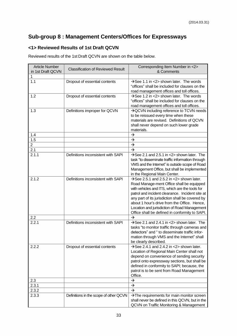
(2014.03.31)
33
Sub-group 8 : Management Centers/Offices for Expressways
<1> Reviewed Results of 1st Draft QCVN
Reviewed results of the 1st Draft QCVN are shown on the table below.
Article Number
in 1st Draft QCVN Classification of Reviewed Result
Corresponding Item Number in <2>
& Comments
1
1.1 Dropout of essential contents See 1.1 in <2> shown later. The words
“offices” shall be included for clauses on the
road management offices and toll offices.
1.2 Dropout of essential contents See 1.2 in <2> shown later. The words
“offices” shall be included for clauses on the
road management offices and toll offices.
1.3 Definitions improper for QCVN QCVN including reference to TCVN needs
to be reissued every time when these
materials are revised. Definitions of QCVN
shall never depend on such lower grade
materials.
1.4
1.5
2
2.1
2.1.1 Definitions inconsistent with SAPI See 2.1 and 2.5.1 in <2> shown later. The
task “to disseminate traffic information through
VMS and the Internet” is outside scope of Road
Management Office, but shall be implemented
in the Regional Main Center.
2.1.2 Definitions inconsistent with SAPI See 2.5.1 and 2.5.2 in <2> shown later.
Road Manage-ment Office shall be equipped
with vehicles and ITS, which are the tools for
patrol and incident clearance. Incident site at
any part of its jurisdiction shall be covered by
about 1 hour’s drive from the Office. Hence,
Location and jurisdiction of Road Management
Office shall be defined in conformity to SAPI.
2.2
2.2.1 Definitions inconsistent with SAPI See 2.1 and 2.4.1 in <2> shown later. The
tasks “to monitor traffic through cameras and
detectors” and “ to disseminate traffic infor-
mation through VMS and the Internet” shall
be clearly described.
2.2.2 Dropout of essential contents See 2.4.1 and 2.4.2 in <2> shown later.
Location of Regional Main Center shall not
depend on convenience of sending security
patrol onto expressway sections, but shall be
defined in conformity to SAPI; because, the
patrol is to be sent from Road Management
Office.
2.3
2.3.1
2.3.2
2.3.3 Definitions in the scope of other QCVN The requirements for main monitor screen
shall never be defined in this QCVN, but in the
QCVN on Traffic Monitoring & Management
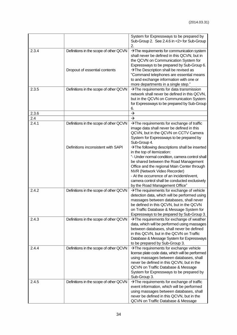
(2014.03.31)
34
System for Expressways to be prepared by
Sub-Group 2. See 2.4.6 in <2> for Sub-Group
2.
2.3.4 Definitions in the scope of other QCVN
Dropout of essential contents
The requirements for communication system
shall never be defined in this QCVN, but in
the QCVN on Communication System for
Expressways to be prepared by Sub-Group 6.
The Description shall be revised as
“Command telephones are essential means
to and exchange information with one or
more departments in a single step.”
2.3.5 Definitions in the scope of other QCVN The requirements for data transmission
network shall never be defined in this QCVN,
but in the QCVN on Communication System
for Expressways to be prepared by Sub-Group
6.
2.3.6
2.4
2.4.1 Definitions in the scope of other QCVN
Definitions inconsistent with SAPI
The requirements for exchange of traffic
image data shall never be defined in this
QCVN, but in the QCVN on CCTV Camera
System for Expressways to be prepared by
Sub-Group 4.
The following descriptions shall be inserted
in the top of itemization:
“- Under normal condition, camera control shall
be shared between the Road Management
Office and the regional Main Center through
NVR (Network Video Recorder)
- At the occurrence of an incident/event,
camera control shall be conducted exclusively
by the Road Management Office”
2.4.2 Definitions in the scope of other QCVN The requirements for exchange of vehicle
detection data, which will be performed using
massages between databases, shall never
be defined in this QCVN, but in the QCVN
on Traffic Database & Message System for
Expressways to be prepared by Sub-Group 3.
2.4.3 Definitions in the scope of other QCVN The requirements for exchange of weather
data, which will be performed using massages
between databases, shall never be defined
in this QCVN, but in the QCVN on Traffic
Database & Message System for Expressways
to be prepared by Sub-Group 3.
2.4.4 Definitions in the scope of other QCVN The requirements for exchange vehicle
license plate code data, which will be performed
using massages between databases, shall
never be defined in this QCVN, but in the
QCVN on Traffic Database & Message
System for Expressways to be prepared by
Sub-Group 3.
2.4.5 Definitions in the scope of other QCVN The requirements for exchange of traffic
event information, which will be performed
using massages between databases, shall
never be defined in this QCVN, but in the
QCVN on Traffic Database & Message
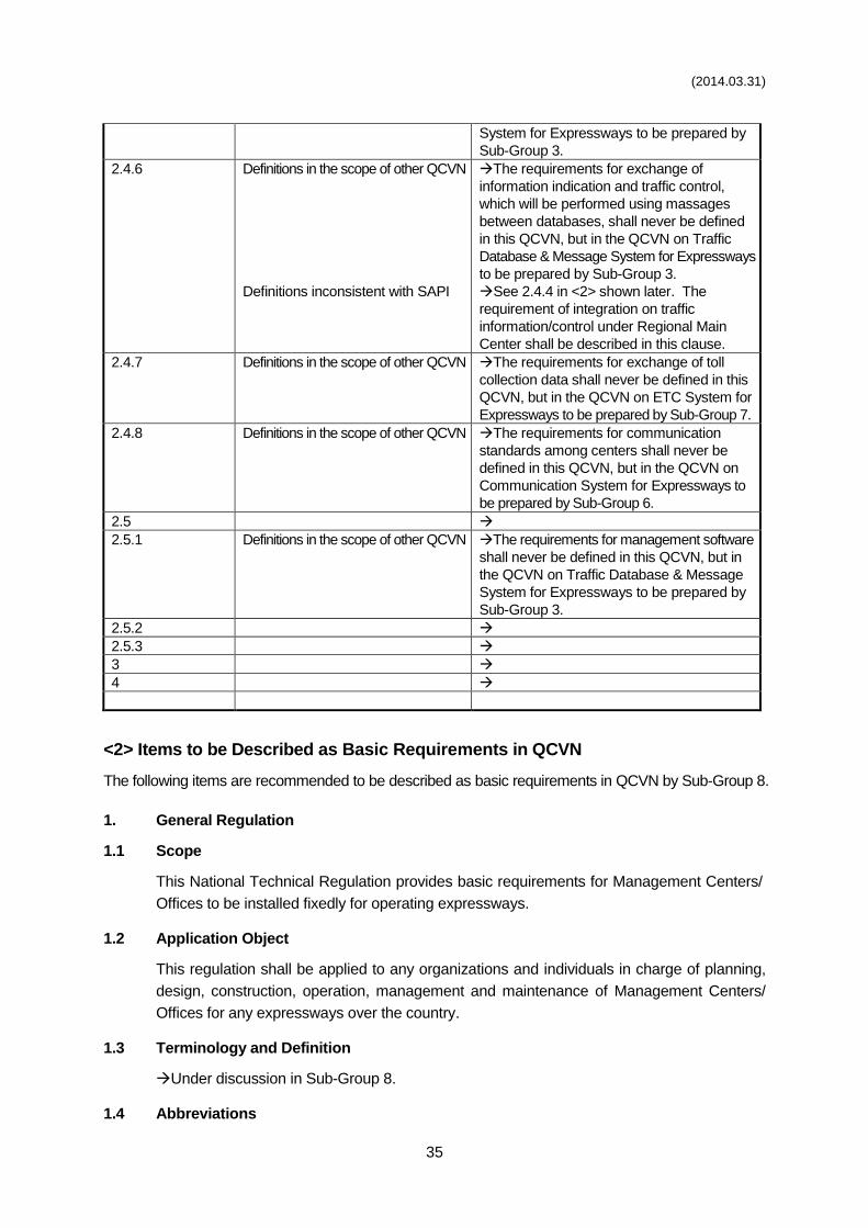
(2014.03.31)
35
System for Expressways to be prepared by
Sub-Group 3.
2.4.6 Definitions in the scope of other QCVN
Definitions inconsistent with SAPI
The requirements for exchange of
information indication and traffic control,
which will be performed using massages
between databases, shall never be defined
in this QCVN, but in the QCVN on Traffic
Database & Message System for Expressways
to be prepared by Sub-Group 3.
See 2.4.4 in <2> shown later. The
requirement of integration on traffic
information/control under Regional Main
Center shall be described in this clause.
2.4.7 Definitions in the scope of other QCVN The requirements for exchange of toll
collection data shall never be defined in this
QCVN, but in the QCVN on ETC System for
Expressways to be prepared by Sub-Group 7.
2.4.8 Definitions in the scope of other QCVN The requirements for communication
standards among centers shall never be
defined in this QCVN, but in the QCVN on
Communication System for Expressways to
be prepared by Sub-Group 6.
2.5
2.5.1 Definitions in the scope of other QCVN The requirements for management software
shall never be defined in this QCVN, but in
the QCVN on Traffic Database & Message
System for Expressways to be prepared by
Sub-Group 3.
2.5.2
2.5.3
3
4
<2> Items to be Described as Basic Requirements in QCVN
The following items are recommended to be described as basic requirements in QCVN by Sub-Group 8.
1. General Regulation
1.1 Scope
This National Technical Regulation provides basic requirements for Management Centers/
Offices to be installed fixedly for operating expressways.
1.2 Application Object
This regulation shall be applied to any organizations and individuals in charge of planning,
design, construction, operation, management and maintenance of Management Centers/
Offices for any expressways over the country.
1.3 Terminology and Definition
Under discussion in Sub-Group 8.
1.4 Abbreviations
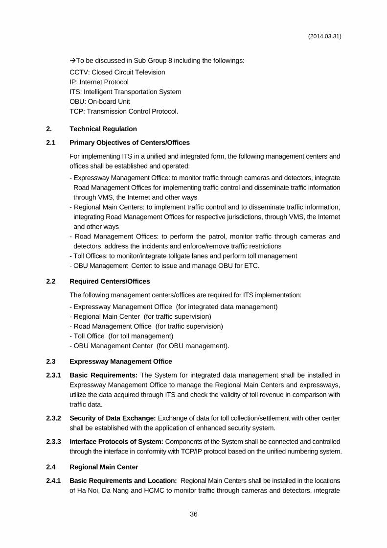
(2014.03.31)
36
To be discussed in Sub-Group 8 including the followings:
CCTV: Closed Circuit Television
IP: Internet Protocol
ITS: Intelligent Transportation System
OBU: On-board Unit
TCP: Transmission Control Protocol.
2. Technical Regulation
2.1 Primary Objectives of Centers/Offices
For implementing ITS in a unified and integrated form, the following management centers and
offices shall be established and operated:
- Expressway Management Office: to monitor traffic through cameras and detectors, integrate
Road Management Offices for implementing traffic control and disseminate traffic information
through VMS, the Internet and other ways
- Regional Main Centers: to implement traffic control and to disseminate traffic information,
integrating Road Management Offices for respective jurisdictions, through VMS, the Internet
and other ways
- Road Management Offices: to perform the patrol, monitor traffic through cameras and
detectors, address the incidents and enforce/remove traffic restrictions
- Toll Offices: to monitor/integrate tollgate lanes and perform toll management
- OBU Management Center: to issue and manage OBU for ETC.
2.2 Required Centers/Offices
The following management centers/offices are required for ITS implementation:
- Expressway Management Office (for integrated data management)
- Regional Main Center (for traffic supervision)
- Road Management Office (for traffic supervision)
- Toll Office (for toll management)
- OBU Management Center (for OBU management).
2.3 Expressway Management Office
2.3.1 Basic Requirements: The System for integrated data management shall be installed in
Expressway Management Office to manage the Regional Main Centers and expressways,
utilize the data acquired through ITS and check the validity of toll revenue in comparison with
traffic data.
2.3.2 Security of Data Exchange: Exchange of data for toll collection/settlement with other center
shall be established with the application of enhanced security system.
2.3.3 Interface Protocols of System: Components of the System shall be connected and controlled
through the interface in conformity with TCP/IP protocol based on the unified numbering system.
2.4 Regional Main Center
2.4.1 Basic Requirements and Location: Regional Main Centers shall be installed in the locations
of Ha Noi, Da Nang and HCMC to monitor traffic through cameras and detectors, integrate
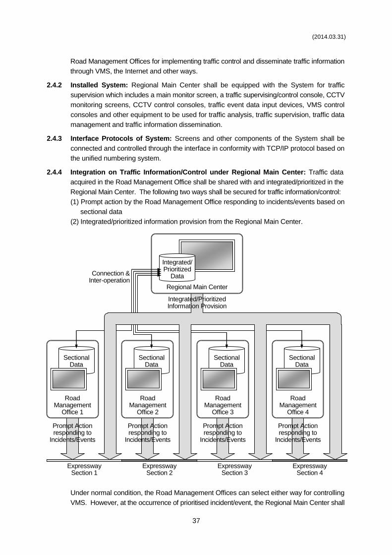
(2014.03.31)
37
Road Management Offices for implementing traffic control and disseminate traffic information
through VMS, the Internet and other ways.
2.4.2 Installed System: Regional Main Center shall be equipped with the System for traffic
supervision which includes a main monitor screen, a traffic supervising/control console, CCTV
monitoring screens, CCTV control consoles, traffic event data input devices, VMS control
consoles and other equipment to be used for traffic analysis, traffic supervision, traffic data
management and traffic information dissemination.
2.4.3 Interface Protocols of System: Screens and other components of the System shall be
connected and controlled through the interface in conformity with TCP/IP protocol based on
the unified numbering system.
2.4.4 Integration on Traffic Information/Control under Regional Main Center: Traffic data
acquired in the Road Management Office shall be shared with and integrated/prioritized in the
Regional Main Center. The following two ways shall be secured for traffic information/control:
(1) Prompt action by the Road Management Office responding to incidents/events based on
sectional data
(2) Integrated/prioritized information provision from the Regional Main Center.
Under normal condition, the Road Management Offices can select either way for controlling
VMS. However, at the occurrence of prioritised incident/event, the Regional Main Center shall
Expressway Section 1
Expressway Section 2
Expressway Section 3
Expressway Section 4
Road Management
Office 1
Road Management
Office 2
Road Management
Office 3
Road Management
Office 4
Integrated/Prioritized Information Provision
Prompt Action responding to
Incidents/Events
Connection & Inter-operation
Regional Main Center
Integrated/ Prioritized
Data
Sectional Data
Sectional Data
Sectional Data
Sectional Data
Prompt Action responding to
Incidents/Events
Prompt Action responding to
Incidents/Events
Prompt Action responding to
Incidents/Events
(2014.03.31)
38
enforce the VMS control in the way (2) in order to perform the most effective control over
the whole expressway network and to achieve the advantages below. This is the requisite
integration in the results of SAPI.
2.5 Road Management Office
2.5.1 Basic Requirements and Location: A Road Management Office shall be installed in each
expressway section, which is a jurisdiction covered by about an hour’s drive from the office, to
perform the patrol, monitor traffic through cameras and detectors, address the incidents and
enforce/remove traffic restrictions.
2.5.2 Installed System: Road Management Office shall be equipped with the System for traffic
supervision which includes CCTV control consoles, traffic event data input devices and other
equipment for traffic control in cooperation with the patrol crews and vehicles, the police and
ambulance service.
2.5.3 Interface Protocols of System: Screens and other components of the System shall be
connected and controlled through the interface in conformity with TCP/IP protocol based on
the unified numbering system.
2.6 Toll Office
2.6.1 Basic Requirements and Location: A Toll Office shall be set up in each tollgate, which has
two or more tollgate lanes and booths, to monitor/integrate tollgate lanes and perform toll
management.
2.6.2 Installed System: Toll Office shall be equipped with the System which executes toll
management.
2.6.3 Security of Data Exchange: Exchange of data for toll collection/settlement with roadside and
other center shall be established with the application of enhanced security system.
2.6.4 Interface Protocols of System: Components of the System shall be connected and controlled
through the interface in conformity with TCP/IP protocol based on the unified numbering
system.
2.7 OBU Management Center
2.7.1 Basic Requirements and Location: OBU Management Center shall be set up in the Vietnam
Register to issue and manage OBU for ETC.
2.7.2 Installed System: OBU Management Center shall be equipped with the System for OBU
management which issues OBU and manages registration/invalidation data of OBU.
2.7.3 Security of Data Exchange: Exchange of data for validation check of OBU with toll office and
other center shall be established with the application of enhanced security system.
2.7.4 Interface Protocols of System: Components of the System shall be connected and controlled
through the interface in conformity with TCP/IP protocol based on the unified numbering
system.
2.8 Requirements on Major Components
2.8.1 XXXXXXX (=Major Component 1)

(2014.03.31)
39
To be discussed in Sub-Group 8.
2.8.2 XXXXXXX (=Major Component 2)
To be discussed in Sub-Group 8.
3. Regulation on Management
To be discussed in Sub-Group 8.
4. Implementing Organization
To be discussed in Sub-Group 8.
添付資料-3
DRAFT QCVN OF
TRAFFIC MONITORING AND MANAGEMENT FOR EXPRESSWAYS
( SUB-GROUP 2 )
SOCIALIST REPUBLIC OF VIETNAM
QCVN XX:2014/BGTVT
NATIONAL REGULATION ON TRAFFIC MONITORING AND MANAGEMENT SYSTEM FOR
EXPRESSWAYS
Quy chuẩn Kỹ thuật về Hệ thống Điều hành Giao thông
Đường cao tốc
HA NOI - 2014
1ST DRAFT
(Sub-Group 2) 2014.03.30
NATIONAL TECHNICAL REGULATION QCVN XX:2014/BGTVT
2
Foreword
QCVN XX:2014/BGTVT was compiled by the Drafting Department for National
Technical Regulation on Traffic Monitoring and Management System for Expressways
(established under the Decision No. 2251/QĐ-BGTVT on July 31st 2013 of MOT),
approved by the Ministry of Science and Technology, and issued by Ministry of
Transportation in accordance with the Circular No. ....../2014/TT - BGTVT on ......... 2014.
NATIONAL TECHNICAL REGULATION QCVN XX:2014/BGTVT
3
NATIONAL TECHNICAL REGULATION ON TRAFFIC MONITORING AND MANAGEMENT
SYSTEM FOR EXPRESSWAYS
National technical regulation on Trung tâm Quản lý Giao thông Đường cao tốc
1 GENERAL REGULATION .............................................................................................. 5
1.1 Scope ...................................................................................................................... 5
1.2 Application Object .................................................................................................... 5
1.3 Reference Materials ................................................................................................. 5
1.4 Terminology and Definition ...................................................................................... 5
1.5 Abbreviations ........................................................................................................... 6
2 TECHNICAL REGULATION ........................................................................................... 7
2.1 Figuration of TMM System ....................................................................................... 7
2.2 Requirements on Design ...................................................................................... 10
2.3 System Operation Procedure ................................................................................ 10
2.3.1 Procedure of Traffic Monitoring and Management .......................................... 10
2.3.2 Procedure of Automatic Data Collection and Processing ................................ 12
2.3.3 Procedure of Equipments Surveillance and Maintenance ............................... 12
2.4 Technical Requirements on Sub-systems .............................................................. 12
2.4.1 Digital Transmission System ........................................................................... 12
2.4.2 CCTV Camera System for Traffic Monitoring .................................................. 13
2.4.3 System for Vehicle Detection .......................................................................... 14
2.4.4 System for Event Management ....................................................................... 16
2.4.5 System for Vehicle Axle Load Control ............................................................. 17
2.4.6 System for Traffic Information Provision ......................................................... 18
2.4.7 Communication System .................................................................................. 20
2.4.8 Emergency Telephone System ....................................................................... 20
2.4.9 Equipment Surveillance System ..................................................................... 21
2.4.10 Traffic Operation and Management Center ..................................................... 22
2.4.11 Toll Collection System .................................................................................... 23
3 REGULATION ON MANAGEMENT ............................................................................. 24
4 IMPLEMENTING ORGANIZATION ............................................................................... 24
NATIONAL TECHNICAL REGULATION QCVN XX:2014/BGTVT
4
APPENDIX A: TECHNOLOGY OF VEHICLE DETECTION ................................................. 25
A.1. Vehicle Detection by Ultrasonic Type ........................................................................ 25
A.2. Vehicle Detection by Image Recognition Type .......................................................... 25
APPENDIX B: TECHNOLOGY OF WEIGH IN MOTION ...................................................... 27
NATIONAL TECHNICAL REGULATION QCVN XX:2014/BGTVT
5
1 GENERAL REGULATION
1.1 Scope
This technical regulation provides basic requirements and directions on function,component
figuration, operation method for infrastructure and equipments system of traffic monitoring
and management system on expressway sections. Compulsory and optional sub-systems
shall be regulated to secured the unification, integration, communication connection and data
exchange among components within the system and among systems which are developed
highway traffic network.
1.2 Application Object
The technical regulation is applied for related individuals, organizations during development,
investment, control and operation of expressway monitoring and management system.
1.3 Reference materials
1.3.1. ISO 14813-1:2007 - Intelligent transport systems – Reference model architecture(s) for
the ITS sector – Part 1: ITS service domains, service groups and services
1.3.2. QCVN 41:2012/BGTVT - National technical regulation on Highway Signs
1.3.3. QCVN …:2014/BGTVT - National technical regulation on Expressway Management
Center
1.3.4. QCVN …:2014/BGTVT - National technical regulation on Automated Traffic Signs on
Expressways
1.3.5. QCVN …:2014/BGTVT - National technical regulation on CCTV Camera System for
Expressways
1.3.6. QCVN …:2014/BGTVT - National technical regulation on Communication System for
Expressways
1.3.7. QCVN …:2014/BGTVT - National technical regulation on Automatic Toll Collection for
Expressways
1.3.8. TCCS 01:2008/VRA – Basic Standards on Road One-stop Tollgates using Barencode
Prints
1.3.9. TCVN 8665:2011 - Fiber optics for Telecommunications Network - General Technical
Requirements
1.3.10. TCVN 8698:2011 - Telecommunication network - bronze-strand information cable
CAT.5, Cat.5e - Technical Requirements
1.4 Terminology and Definition
All terminologies in this regulation shall be defined as below:
1.4.1. Blind spot
NATIONAL TECHNICAL REGULATION QCVN XX:2014/BGTVT
6
The area out of site where operator shall not be capable of monitoring by captured images
from CCTV camera..
1.4.2. Vehicle detectors
This equipment shall be capable of measuring vehicle volume, speed and road occupancy at
one place on expressway in order to analyze congestion condition as well as to automatically
recognize highway incidents.
1.4.3. Vehicle volume
The vehicle volume shall be calculated on the basic of counted number passing one fixed
point within a period of time T - vehicle counting cycle. The measured volume shall be listed
by lane and by classification in vehicle counting cycles..
1.4.4. Average speed
The average value of all measured vehicle speeds in vehicle counting cycle.
1.4.5. Road occupancy
The ratio between the time for a detector to recognize vehicle in area and the time of vehicle
counting cycle.
1.4.6. Event
The situation affecting to traffic condition included traffic incidents, dangerous weather, traffic
congestion, maintenance work and traffic restrictions.
1.4.7. Incident
An unusual event without in advance affecting or interrupting traffic condition included traffic
accidents, broken down vehicles, obstacles, reversing vehicles, vandalism or natural disaster
on road
1.4.8. Weigh in Motion
The equipment to measure axle load and total vehicle while moving normally and nonstop at
weigh station.
1.4.9. Electronic Vehicle Identification Equipment
The equipment shall be installed on board with an identity encode of vehicle so that a reader
can automatically read through radio wave communication.
1.4.10. Procedure of Close Toll Collection
The toll shall be calculated based on actual distance the vehicle travels by controlling
information since the vehicle access to the entry, and it shall be collected at the exit on
expressway.
1.5 Abbreviations
QCVN National Technical Regulation (according to Law on Technical Standard and
Technical Regulation)
NATIONAL TECHNICAL REGULATION QCVN XX:2014/BGTVT
7
TCVN National Standard (according to Law on Technical Standard and Regulation)
GSĐHGT Traffic Monitoring and Management System
QLĐHGT Traffic Management Center
PTZ Pan Tite Zoom (Quay, quét, thu phóng)
DB Data Base
IP Internet Protocol (Giao thức mạng Internet)
MTBF Mean Time Between Failures (thời gian trung bình lỗi hoạt động)
MTTR Mean Time Between Failures (thời gian trung bình để sửa chữa)
VMS Variable Message Sign (Biển chỉ dẫn thông tin thay đổi được)
2 TECHNICAL REGULATION
2.1 Figuration of TMM System
2.1.1. Traffic monitoring and Management System shall be developed to support the
operation, control and maintenance for expressways which are put in utilization. The system
shall have functions of collecting, processsing, determining and transmitting information and
demand to competent authorities and road users, with the aim of properly understanding the
operation status and cooperating to secure traffic safety, improve quality and effectiveness in
highway management.
2.1.2. The figuration of TMM System shall be defined on the basic of Necessary Services for
User in reference architecture of Intelligent Transportation System (ISO 14813-1:2007) with
below compulsory equipment packages and optional equipment packages:
a) Compulsory equipment packages included:
1. Digital transmission System: shall secure communication between roadside
monitoring equipments and operation center, and shall connect among road
management offices/centers.
2. CCTV Monitoring System: shall help operators remotely monitor traffic images; shall
supervise traffic flows through screens or large-size screen wall in operation office;
and shall provide video images to authorities and public.
3. Vehice Detection: shall collect, analyse, report and store datas on condition
description and performance of road system, shall recognize traffic congestion or
incidents in order to notify road users.
4. System for Event Management: shall provide equipments to automatically generating
data from system for vehicle detection, system for vehicle axle load measurement,
weather information system so that output data can be used for automatically
notifying and managing traffic events which may affect to highway traffic safety.
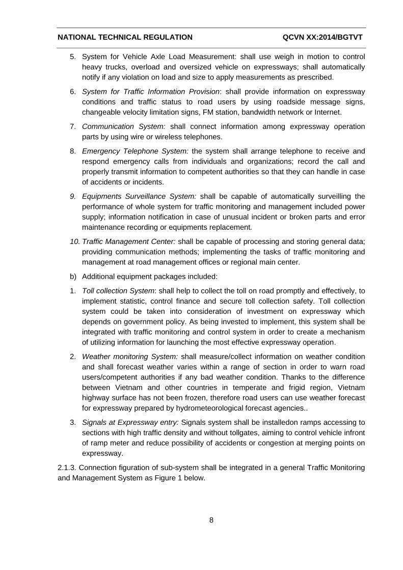
NATIONAL TECHNICAL REGULATION QCVN XX:2014/BGTVT
8
5. System for Vehicle Axle Load Measurement: shall use weigh in motion to control
heavy trucks, overload and oversized vehicle on expressways; shall automatically
notify if any violation on load and size to apply measurements as prescribed.
6. System for Traffic Information Provision: shall provide information on expressway
conditions and traffic status to road users by using roadside message signs,
changeable velocity limitation signs, FM station, bandwidth network or Internet.
7. Communication System: shall connect information among expressway operation
parts by using wire or wireless telephones.
8. Emergency Telephone System: the system shall arrange telephone to receive and
respond emergency calls from individuals and organizations; record the call and
properly transmit information to competent authorities so that they can handle in case
of accidents or incidents.
9. Equipments Surveillance System: shall be capable of automatically surveilling the
performance of whole system for traffic monitoring and management included power
supply; information notification in case of unusual incident or broken parts and error
maintenance recording or equipments replacement.
10. Traffic Management Center: shall be capable of processing and storing general data;
providing communication methods; implementing the tasks of traffic monitoring and
management at road management offices or regional main center.
b) Additional equipment packages included:
1. Toll collection System: shall help to collect the toll on road promptly and effectively, to
implement statistic, control finance and secure toll collection safety. Toll collection
system could be taken into consideration of investment on expressway which
depends on government policy. As being invested to implement, this system shall be
integrated with traffic monitoring and control system in order to create a mechanism
of utilizing information for launching the most effective expressway operation.
2. Weather monitoring System: shall measure/collect information on weather condition
and shall forecast weather varies within a range of section in order to warn road
users/competent authorities if any bad weather condition. Thanks to the difference
between Vietnam and other countries in temperate and frigid region, Vietnam
highway surface has not been frozen, therefore road users can use weather forecast
for expressway prepared by hydrometeorological forecast agencies..
3. Signals at Expressway entry: Signals system shall be installedon ramps accessing to
sections with high traffic density and without tollgates, aiming to control vehicle infront
of ramp meter and reduce possibility of accidents or congestion at merging points on
expressway.
2.1.3. Connection figuration of sub-system shall be integrated in a general Traffic Monitoring
and Management System as Figure 1 below.
9
Monitoring
Camera
Vehicle
detector
r
WIM
Station
Tollgate Traffic
Signals
Electronic
Signs
Terminal
telephone
Camera
Management
Vehicle Detection Data
Management
Axle Load Measuring
Management
Toll collection
Management
Road User
Interface
Information providing
Management
Emergency calls receiving
management
Event
Management
Communication
Management
Weather Information
Management
Lights Controlling Management
Digital Transmission System for on Route
Digital Transmission System for Inter-centers
Road User Interface
(wall screen, station server)
Data collection
and processing
ROADSIDE
EQUIPMENTS
AND STATIONS
ROAD
MANAGEMENT
OFFICES
REGIONAL
MAIN CENTER Communica
tion
Data storing
Management
Traffic information
Provision
Figure 1. Figuration Map of Components in Traffic Monitoring and Management System for Expressways
Weather
Sensor
Equipment surveillance
Management
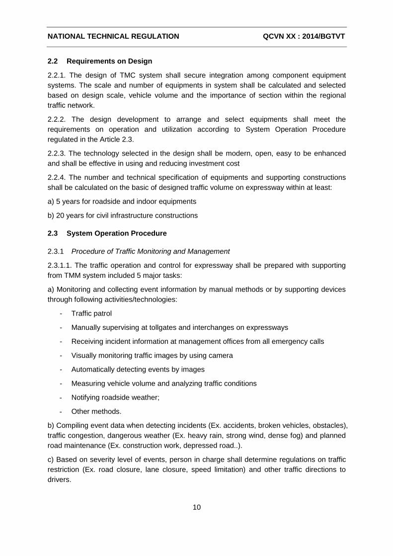
NATIONAL TECHNICAL REGULATION QCVN XX : 2014/BGTVT
10
2.2 Requirements on Design
2.2.1. The design of TMC system shall secure integration among component equipment
systems. The scale and number of equipments in system shall be calculated and selected
based on design scale, vehicle volume and the importance of section within the regional
traffic network.
2.2.2. The design development to arrange and select equipments shall meet the
requirements on operation and utilization according to System Operation Procedure
regulated in the Article 2.3.
2.2.3. The technology selected in the design shall be modern, open, easy to be enhanced
and shall be effective in using and reducing investment cost
2.2.4. The number and technical specification of equipments and supporting constructions
shall be calculated on the basic of designed traffic volume on expressway within at least:
a) 5 years for roadside and indoor equipments
b) 20 years for civil infrastructure constructions
2.3 System Operation Procedure
2.3.1 Procedure of Traffic Monitoring and Management
2.3.1.1. The traffic operation and control for expressway shall be prepared with supporting
from TMM system included 5 major tasks:
a) Monitoring and collecting event information by manual methods or by supporting devices
through following activities/technologies:
- Traffic patrol
- Manually supervising at tollgates and interchanges on expressways
- Receiving incident information at management offices from all emergency calls
- Visually monitoring traffic images by using camera
- Automatically detecting events by images
- Measuring vehicle volume and analyzing traffic conditions
- Notifying roadside weather;
- Other methods.
b) Compiling event data when detecting incidents (Ex. accidents, broken vehicles, obstacles),
traffic congestion, dangerous weather (Ex. heavy rain, strong wind, dense fog) and planned
road maintenance (Ex. construction work, depressed road..).
c) Based on severity level of events, person in charge shall determine regulations on traffic
restriction (Ex. road closure, lane closure, speed limitation) and other traffic directions to
drivers.
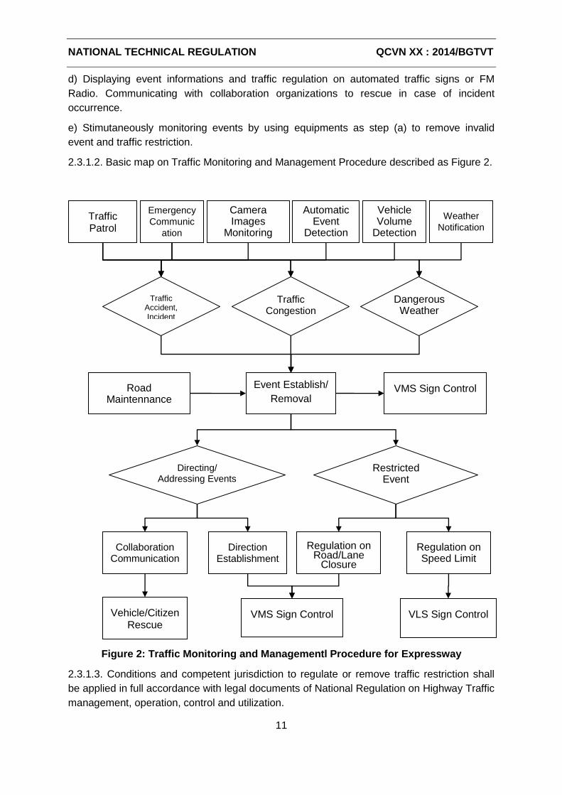
NATIONAL TECHNICAL REGULATION QCVN XX : 2014/BGTVT
11
d) Displaying event informations and traffic regulation on automated traffic signs or FM
Radio. Communicating with collaboration organizations to rescue in case of incident
occurrence.
e) Stimutaneously monitoring events by using equipments as step (a) to remove invalid
event and traffic restriction.
2.3.1.2. Basic map on Traffic Monitoring and Management Procedure described as Figure 2.
Figure 2: Traffic Monitoring and Managementl Procedure for Expressway
2.3.1.3. Conditions and competent jurisdiction to regulate or remove traffic restriction shall
be applied in full accordance with legal documents of National Regulation on Highway Traffic
management, operation, control and utilization.
Traffic Accident, Incident
Emergency
Communic
ation
Traffic Patrol
Camera Images
Monitoring
Vehicle Volume
Detection
Weather
Notification
Automatic Event
Detection
Traffic Congestion
Dangerous Weather
Event Establish/
Removal
Directing/ Addressing Events
Restricted Event
Regulation on Road/Lane
Closure
Direction Establishment
Regulation on Speed Limit
VLS Sign Control
VMS Sign Control
Collaboration Communication
VMS Sign Control
Vehicle/Citizen Rescue
Road Maintennance
NATIONAL TECHNICAL REGULATION QCVN XX : 2014/BGTVT
12
2.3.2 Procedure of Automatically Collecting and Processing Traffic Data
2.3.2.1. Traffic data collection shall be implemented at stations on expressway in order to
continuously record the traffic flow distribution and change in disconnected time (Ex. 5 mins,
15mins, every hour per day, every day per week, monthly, annually). Processors at center shall
automatically analyze the data and provide event notification on prone traffic congestion on
each section.
2.3.2.2. Event Management System shall collect data from system for axle load
measurement, system for vehicle detection, weather information system in order to
automatically provide notification on congestion, bad weather and violation affecting to traffic
safety on expressways. The system shall capture images of violated vehicle, identify license
plate and automatically store data to transmit for competent authorities to handle as
regulation.
2.3.2.3. Expressway traffic data shall be collected continuously 24 hours a day, 7 days a
week and 365 days a year. These data shall be stored and provided to responsible
organization for compiling reports on section plan, traffic operation and distribution policies,
settling measurements to avoid highway accidents and congestion.
2.3.3 Procedure of Equipment Maintenance
2.3.3.1. All the equipments for power supplying, sensoring and information processing in
traffic monitoring and management system shall be managed, checked and kept under usual
operation status within 24 hours a day, 7 days a week and 365 days a year
2.3.3.2. Equipment surveillance system shall collect data on operation supervision of
equipment and power supply to generally manage at a DataBase center. Surveilling software
shall process and automatically evaluate data to recognize and notify in case of failure or
unusual condition of those equipments.
2.3.3.3. The technician at Traffic Management Center shall continuously surveil the
operation of equipment system by using software; taking note in diary on operation status of
equipments and make maintenance plan in accordance with regulation by manufacturer.
2.4 Technical requirements on Sub-systems
2.4.1 Digital Transmission System
2.4.1.1. Digital transmission system shall be developed to secure connection among
equipments on roadside, at tollgate, in service office and traffic management center. System
design shall use fiber optic transmission methods for distance over 100m, twisted-pair cable
for the device at a close distance or radio transmission at specific locations. Transmission
network in the system should be built on the basic o.f Ethernet protocol.
2.4.1.2. Digital transmission system shall be designed in layer structure including:
a) Backbone layer shall connect among stations on section, Road management
NATIONAL TECHNICAL REGULATION QCVN XX : 2014/BGTVT
13
offices/centers. The bandwidth for this layer shall be ≥ 10Gbps.
b) Boundary layer shall connect among equipment groups on roadside, at stations or centers.
The bandwidth for this layer shall be ≥ 1000Mbps.
c) Equipment layer shall connect among equipments within scope of an office or a installing
location on roadside. The bandwidth for this layer shall be ≥ 100Mbps.
2.4.1.3.Digital transmission system shall be designed with application of Ring topology with
backup feature to automatically recover in case of cable interuption at a connection point on
circuit.
2.4.1.4. Digital transmission system shall be installed with system for administration, Quality
of Service (QoS) so that it can monitor the apperance and recovering of incidents, record
and repair network system figuration, estimate the location of incident and switch to backup
cables.
2.4.1.5. The construction for the cable of transmission system shall comply with general
standard for telecomunication network infrastructure and highway design. In where, optical
cable shall be used in accordance with the standard TCVN 8665:2011 and twisted-pair cable
in accordance with the minimum standard for Cat5 in TCVN 8698:2011.
2.4.2 CCTV System for Traffic Monitoring
2.4.2.1. The system shall provide visual image of road condition and traffic flow on route
around the location of camera, which help operator to clearly understand the road conditions.
Traffic monitoring camera shall be in used with two aims of:
a) Visually supervise traffic flow and recognize accidents and incidents on section
b) Visually recognize the dangerous conditions of weather such as fog or heavy rain to
provide notification for drivers to prevent accidents
2.4.2.2. The monitored locations:
a) Entrance/exit spots, interchanges between expressway sections and other roads
b) Highly congestion and incident-prone sections, flood or erosion-prone spots on expressway
c) On backbone expressway with high volume of mass vehicle, monitoring camera shall be
covered continuously along the main section, minimizing the length of the blind spots..
2.4.2.3. System Architecture
a) Monitoring cameras shall be installed at entrance/exit points, interchanges; overall
cameras shall be installed at highly incident-prone points, whose function of remotely panning
and titing (PTZ).
b) Monitoring cameras along major roads in the expressways shall be installed to monitor
continuously step by step, with the gap between two cameras is approximately 50 ÷ 1000m.
Captured images from monitoring cameras along the section shall consist of all road lanes
on both directions within monitored range.
NATIONAL TECHNICAL REGULATION QCVN XX : 2014/BGTVT
14
c) The data from the camera should be compressed as well as removed static images
(feature of automatically detecting new radio motion) to minimize the amount of
communication data and to process at center, then transmitted to the center by using the
digital data transmission system.
d) Roadside equipments shall have components to install (poles or brackets) and power
supply protector.
e) At management offices, radio datas shall be automatically recorded, enencoded and
displayed on central monitoring screens and processed to achieve outputs of vehicle
detection as requirements.
2.4.2.4. Image data protocol: based on IP, which remotely monitor from far distance on IP
network to support standards of Open Network Video Interface Forum (ONVIF).
2.4.2.5. Basic technical requirements on equipments in system shall comply with
QCVN ...:2014/BGTVT “National technical regulation on traffic monitoring CCTV camera
system on expressway”.
2.4.3 System for Vehicle Detection
2.4.3.1. System for vehicle detection shall be installed to automatically collect traffic data
with below parameters:
a) Vehicle volume shall be categorized by the length of vehicle (L) including:
- Ordinary vehicle includes car, bus and light truck with the length: L ≤ 6m
- Large vehicle includes large bus, truck with the length: 6m < L ≤ 12m
- Extra-large vehicle includes traler truck, overload and oversize vehicle with the length: L > 12m.
b) The average speed shall be calculated by using this formula (1)
Vtb = (V1 + V2 + ... + Vn) / N (1)
Where: Vi is speed of vehicle No. i, N is the number vehicle in cycle T.
c) Road Occupancy shall be calculated by using this formula (2)
OC = (L1/V1 + L2/V2 + ... + Ln/Vn) / T * 100 (2)
Where: Li, Vi is correspondent to the length and the speed of vehicle No. i in vehicle counting cycle T
2.4.3.2. Policies for vehicle arrangement shall be implemented with the aims of:
a) Control entrance/exit vehicle on expressway
Vehicle detectors shall be arranged on entrance/exit ramps, on the main expressway section
near by interchanges to calculate the number of entrance/exit vehicles on each expressway
section. For sections with close toll collection, it shall be capable of using counting data at
tollgates to control the number of entrance/exit vehicles on each expressway.
b) Define the traffic speed, congestion of each expressway section
To get clear understanding the traffic status on a section, vehicle detectors shall be installed
NATIONAL TECHNICAL REGULATION QCVN XX : 2014/BGTVT
15
in a continuously specified distance on the main expressway. The more vehicle detectors are
installed, it could be more exactly and it take shorter time to recognize congestion. Requirement
on installation is the system must recognize the congestion within maximum 10 minutes.
c) Automatic Event Recognition by Images
Systems for Vehicle detection by image shall be capable of recognizing by video analyzation
on violations that badly affect to traffic safety on expressways, on incidents such as obstacles
so as to notify road users.
d) Vehicle Encode Identification
Automatically recognize vehicle encode identification when passing vehicle detecting point
by optical license plate identifying equipment or electronic vehicle identifying equipment on
board
2.4.3.3. Technology for Vehicle Detection Equipment
Technology for vehicle detection equipment shall be the type of being installed on roadside
without requirement to be buried underground, not destroy the road surface infrastructure
during equipment installation and operation. These two following technologies shall be
considered to select in design: Vehicle detction by ultrasonic type and Vehicle detection by
Image Recognition type which are described in Appendix A.
2.4.3.4. Vehicle detectors which operate in normal condition of weather (without rain) shall
provide the result of traffic volume with maximum tolerance:
a) Vehicle volume ± 5%
b) Vehicle speed ± 5km/h
2.4.3.5. Vehicle detection data at all equipment installed points shall be transmitted to server
at center continuously or in cycle at least 5 mins per time so as to be processed in
accordance with below principles:
a) Cumulation and average calculation
Vehicle detection data server shall automatically calculate and generate the data at different
time and counting cycle (5 mins, 15 mins, hourly, daily, monthly, annually). The procedure of
cumulation and average calculation shall include interruption time when no data collected
from detectors.
b) Supervision of Data Quality
Before using the vehicle detector to transmit data, it shall be checked and evaluated to
supervise failure status. Collected data shall be compared with the threshold of traffic
volume parameters and measurement values at being time. In case of unusual mutation in
collected data, the equipment shall be marked to check. The processing procedure shall be
recovered as normal if no errors or failures in collected data.
c) Data storage
Vehicle detection data shall be restored in DataBase to support statistics within validation
time of at least 3 years.
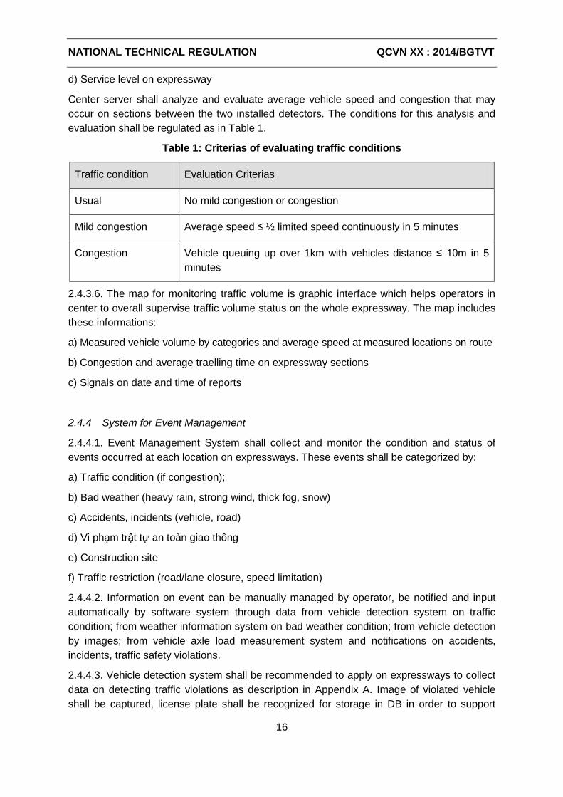
NATIONAL TECHNICAL REGULATION QCVN XX : 2014/BGTVT
16
d) Service level on expressway
Center server shall analyze and evaluate average vehicle speed and congestion that may
occur on sections between the two installed detectors. The conditions for this analysis and
evaluation shall be regulated as in Table 1.
Table 1: Criterias of evaluating traffic conditions
Traffic condition Evaluation Criterias
Usual No mild congestion or congestion
Mild congestion Average speed ≤ ½ limited speed continuously in 5 minutes
Congestion Vehicle queuing up over 1km with vehicles distance ≤ 10m in 5
minutes
2.4.3.6. The map for monitoring traffic volume is graphic interface which helps operators in
center to overall supervise traffic volume status on the whole expressway. The map includes
these informations:
a) Measured vehicle volume by categories and average speed at measured locations on route
b) Congestion and average traelling time on expressway sections
c) Signals on date and time of reports
2.4.4 System for Event Management
2.4.4.1. Event Management System shall collect and monitor the condition and status of
events occurred at each location on expressways. These events shall be categorized by:
a) Traffic condition (if congestion);
b) Bad weather (heavy rain, strong wind, thick fog, snow)
c) Accidents, incidents (vehicle, road)
d) Vi phạm trật tự an toàn giao thông
e) Construction site
f) Traffic restriction (road/lane closure, speed limitation)
2.4.4.2. Information on event can be manually managed by operator, be notified and input
automatically by software system through data from vehicle detection system on traffic
condition; from weather information system on bad weather condition; from vehicle detection
by images; from vehicle axle load measurement system and notifications on accidents,
incidents, traffic safety violations.
2.4.4.3. Vehicle detection system shall be recommended to apply on expressways to collect
data on detecting traffic violations as description in Appendix A. Image of violated vehicle
shall be captured, license plate shall be recognized for storage in DB in order to support

NATIONAL TECHNICAL REGULATION QCVN XX : 2014/BGTVT
17
official handling and secure traffic safety.
2.4.4.4. The license plate of special vehicle shall be monitored as priority vehicle, overload
or oversize vehicle, hazardous material vehicle, vehicle in black list stored in Database of
event management server. When a plate in this database is detected by image recognition,
the system shall automatically compile an event to notify the occurrence of object at the
location of monitoring camera.
2.4.5 System for Vehicle Axle Load Control
2.4.5.1. System configuration
a) Equipments at WIM station:
- Automated sensor for measuring axle load, signal amplication device, measurement
data processing and recording device;
- Device for measuring axle gap, vehicle speed and category;
- Device for recognizing license plate and capturing vehicle through measurement sensor;
- ID Reader for automatic vehicle identification;
- Power supplier, lightning protection and security device and other supporting devices;
- Digital communication device to center.
b) Equipments at operation center:
- Digital communication system shall receive information from weighing in motion station;
- System for recording and storing data, statistic;
- Software for recognizing violation in loading, making the minute and handling as
regulation.
2.4.5.2. WIM stations shall automatically provide these datas if a vehicle passes by:
- Axle load and Axles load group
- Total weight of vehicle
- Velocity
- The distance between middle points of axles
- Vehicle category (by axle)
- License plate number
- Image of license plate and overall image of vehicle passig by sensor
- Station code/location code
- Lane and direction of vehicle
- Time of vehicle passing by
- Weight violation code
NATIONAL TECHNICAL REGULATION QCVN XX : 2014/BGTVT
18
2.4.5.3. Weighing in motion might be installed at entrance/exit toll lane on expressway
(average speed) or on the backbone expressway high speed as described in Appendix B.
The location of WIM, operation regulation, supervision, handling the violating vehicles shall
be implemented as regulated by competent authorities.
2.4.5.4. Measurement equipments (axle load scale) shall be used in system in accordance
with technical requirements on measurement and be approved by competent authorities.
2.4.6 System for Traffic information Provision
2.4.6.1. Classification of provided information
a) Information when controlling vehicles
Based on the characteristics of driving on the highway to give the information to remind
drivers to adhere to traffic rules, avoid driving in tiredness to secure trafic safety when driving.
b) Information at the specified time
Based on the specific time, such as sunset, early morning, night mode, time of high
temperature, easy to sleep, peak traffic on holidays, foggy weather, etc, to put out the
information to remind of safe driving.
c) Information on road condition
Providing expressway users with traffic condition on route, unusual prone-incidents included
traffic accidents, road construction, flood or erosion-prone spots and other information
related to handling directions.
d) Weather forecast information
Provide information on the possibility of strong wind, rain, fog, haze, dust storms, etc .
e) Other informations
Based on the different characteristics of the highway, other useful informatin shall be
provided to the road users.
2.4.6.2. Procedure of information provision
a) The highway information collection, transmission, cancellation and updating shall be
integrated.
b) The entire procedure of collecting, processing, transmitting, cancelling and updating
highway information shall be implemented with strict managing measurement which is
effective, sequenced, practical and feasible. The information shall be collected in a large
range, processed in legally order, accurately displayed, promptly cancelled and updated.
2.4.6.3. Information shall be collected from:
- Equipments of Traffic monitoring and management system;
- Road managing organizations;
- Traffic police;
NATIONAL TECHNICAL REGULATION QCVN XX : 2014/BGTVT
19
- Road implementing and maintaining organizations;
- Service area, tollgates;
- Expressway operating organizations;
- Other information providers.
2.4.6.4. Information processing
If there is no error when inspecting collected information on road and weather conditions, the
information shall be notified on basic of regulation and procesdure by competent authorities
to disseminate information.
2.4.6.5. Sending information
a) The operator should use corresponding information stored in repository to send initially, or
edit the necessary information at being time to send based on the actual situation.
b) When the operators send the necessary information for driving and information at specific
time, they should take consideration of geographic location of the displaying screen, sub-
buildings and road shape as well as the work of displaying from groups of transmission
equipments.
c) Based on location and jurisdiction of the event, the notification on road condition and
weather shall be defined with code so that operator can choose corresponding information to
send.
d) When much information needs to be sent at the same time, it should be managed and
followed as the below priority sequence of disseminating information:
i. Information on road condition, priority for traffic incidents;
ii. Information on weather;
iii. Information at specific time;
iv. Necessary information for driving;
v. Other information.
2.4.6.6. Information cancellation and updating
a) Both necessary information for driving and information at specific time are usual information
to be sent, cancellation and updating shall be followed as regulation.
b) For information on road condition and weather, operators should pay more attention to the
course of the events so as to promptly cancel or update new information, and report as
regulated sequence.
2.4.6.7. Variable message shall be provided by:
a) Electronic traffic signs
b) FM Radio
c) Loudspeaker
NATIONAL TECHNICAL REGULATION QCVN XX : 2014/BGTVT
20
d) Other information systems (Internet, mobile equipments, etc)
2.4.6.8. Electronic traffic signs shall be installed and operated in accordance with National
technical regulation on Electronic traffic signs on expressways (QCVN …:2014/BGTVT).
2.4.7 Communication System
2.4.7.1. The communication system shall be developed with two components::
a) Fixed telephone system shall be used to connect internal offices, stations and other fixed
points.
b) Mobile radio communication system shall be used to connect operational vehicles and
mobile objects on the highway.
2.4.7.2. Terminal equipments in communication system shall be installed at locations depending
on application objects:
a) Traffic management center;
b) Stations and toll lanes;
c) Service area;
d) Expressway managing, implementing and maintaining organizations;
e) Mobile vehicle of patrol crew, rescue team and traffic police.
2.4.7.3. Terminal equipments shal be separated into 2 types depending on using purpose:
a) Command telephone shall be used for managing the expressway implementation and
maintenance.
b) Administration telephone communication shall be used for normal activities. The priority
for connection of administration phone is always lower than the command one..
2.4.7.4. Communication system should be designed with connection throughout the system
to sure internal communications between traffic management center with stations, service
areas and mobile vehicles The system must allow any terminal equipment from to be
capable of making external call through the public switched telephone network.
2.4.7.5. The coverage area for mobile radio commication system should be designed with
capability of connecting to all points along expressway included road management offices,
toll collection area, rest area, parking area and all other areas. The system shall be
oprotected with measures against interference when extending coverage area.
2.4.7.6. Equipments of communication system shall be installed in accordance with
regulations in National technical regulation on Communication system for expressways
QCVN …:2014/BGTVT).
2.4.8 Emergency Telephone System
2.4.8.1. Emergency telephone system shall be used for receiving notification on accidents,
NATIONAL TECHNICAL REGULATION QCVN XX : 2014/BGTVT
21
incidents on expressways from individuals and organizations. The system shall consist of:
a) System of direction signs with emergency telephone number along the road or emergency
telephone booths installed at the area without mobile network coverage.
b) The telephone shall receive emergency calls at Traffic management center to collect and
process information with the aim of properly dispatching rescue team if accidents or incidents
to cooperate with patrol crew, traffic police and ambulance.
2.4.8.2. Direction signs with Emergency telephone number
Direction signs with Emergency telephone number shall be installed along two sides of road
in accordance with regulation on Road signals QCVN 41:2012/BGTVT. The distance
between signs is 500m. The information on signs shall include emergency telephone number
and the location of sign in order for road user to easily locate on the highway
2.4.8.3. Emergency telephone Booths
At the installed location, emergency telephone booths shall be arranged at both two sides of
the highway with a maximum spacing of 1000m. Transmission line connection is established
directly from the Emergency telephone booths to the telephone which receives emergency
calls in the center.
2.4.8.4. Emergency call receiving telephone
The arrangement and operation of Emergency call receiving telephone shall comply with
regulations on design in Technical regulation on Traffic management center on expressways
(QCVN …:2014/BGTVT).
2.4.9 Equipment Surveillance System
2.4.9.1. Equipment surveillance system shall integrate information to assist monitoring
overall operation of all types of equipments in traffic monitoring and management system as
below:
a) Switch devices and network of digital transmission system;
b) CCTV Camera and image storing devices of Traffic monitoring system;
c) Sensors and data processors of Vehicle detection system;
d) Weigh in motion of Axle load measurement system;
e) Electronic signs and other devices of Traffic information providing system;
f) Telephone, call center and broadcast station of Communication System and emergency
telephone system;
g) Server for processing data;
h) Power supplier (UPS battery, solar power);
i) Power monitoring equipment and operating ambient;
j) Equipmetns of Toll collection system;
NATIONAL TECHNICAL REGULATION QCVN XX : 2014/BGTVT
22
k) Sensors of Weather information system;
l) Other equipments.
2.4.9.2. Equipment surveillance software
The surveillance of equipment operation shall be implemented through software interface at
Traffic Management center. This interface can be a combination of software from many
different sub-systems. The role of the implementing organization is to integrate the function
of managing the devices in sub-systems on a unified interface, briefly describing the system
status, making timely notification to the system operator.
2.4.9.3. Monitored information
Monitoring information should be collected periodically and continuously but not interrupt the
operation of equipments. The layout for monitored information shall be classified with priority
as following order:
a) Failure status or operation error of equipment shall be evaluated according to different
severity levels;
b) Notification on unusual activities of equipments;
c) Detailed parameters on equipment performance..
2.4.9.4. Inspection and Notification
Different measures shall be used based on each system and equipment. Typically, the
normal operation will be verified periodically monitoring system by sending a request
command. The time period required will be adjusted for each system and equipment parts.
However, if the system detects parts of any discrepancy, the alarm signal will be switched on
immediately on system components and related equipment to minimize obstruction.
2.4.9.5. Operation diary of equipments
Equipment surveillance system shall save the record of system operation and status of the
system, different devices under a unified format in the database. All incidents and events
must be recorded. Data tracking software will be installed to track and display the logs for
the operation of systems and equipment identified. Therefore, the database is stored will be
used in the calculation of the reliability index system and equipment including MTBF (mean
time between failures) and MTTR (mean time to repair).
2.4.9.6. Power supply monitoring and operation ambient
All devices shall work properly only when the power supply is stable and fully standard
operation ambient. The sensors should be installed at appropriate locations to monitor the
power supply and operation ambient through measured values such as voltage, usage
power and temperature around equipments.
2.4.10 Traffic Operation and Management Center
2.4.10.1. Traffic Monitoring and Management on expressways shall be organized by two
levels:
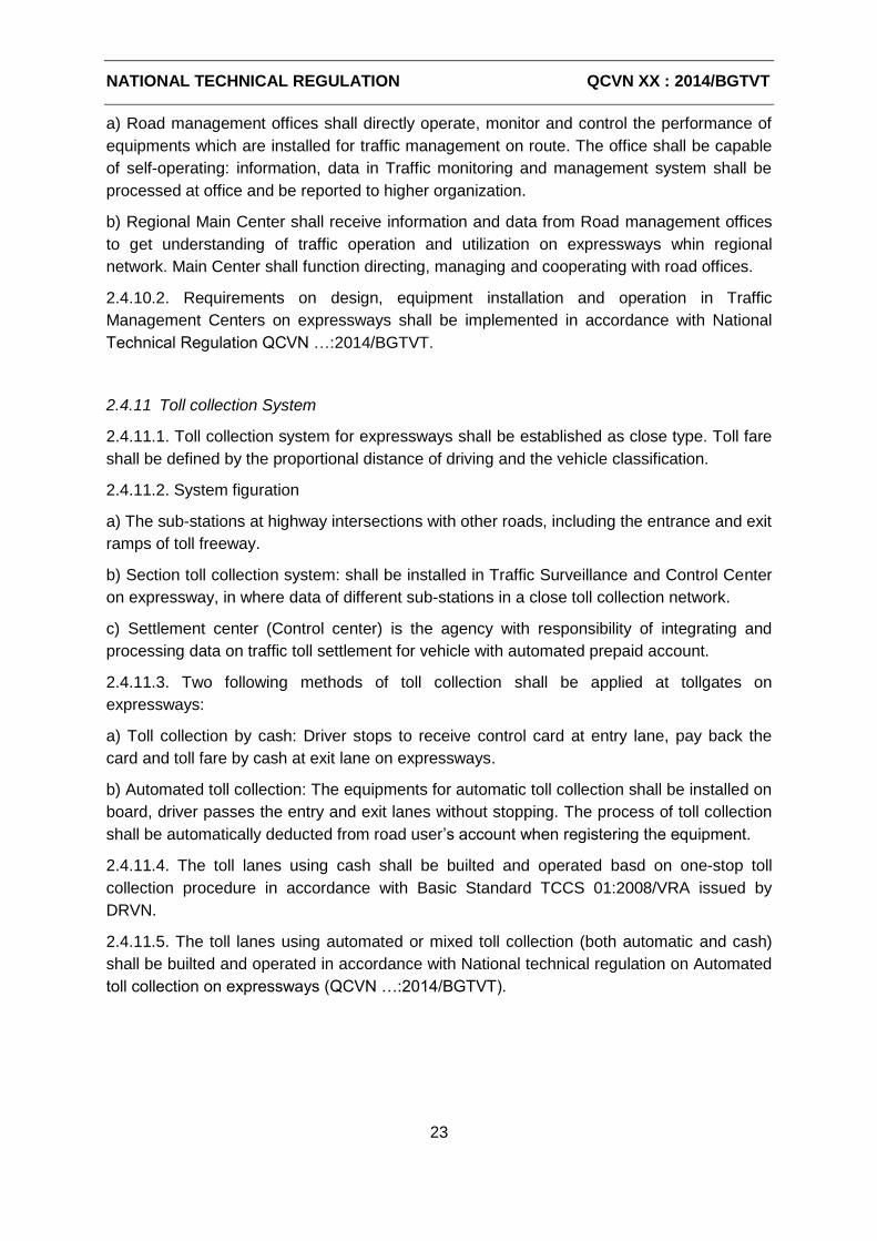
NATIONAL TECHNICAL REGULATION QCVN XX : 2014/BGTVT
23
a) Road management offices shall directly operate, monitor and control the performance of
equipments which are installed for traffic management on route. The office shall be capable
of self-operating: information, data in Traffic monitoring and management system shall be
processed at office and be reported to higher organization.
b) Regional Main Center shall receive information and data from Road management offices
to get understanding of traffic operation and utilization on expressways whin regional
network. Main Center shall function directing, managing and cooperating with road offices.
2.4.10.2. Requirements on design, equipment installation and operation in Traffic
Management Centers on expressways shall be implemented in accordance with National
Technical Regulation QCVN …:2014/BGTVT.
2.4.11 Toll collection System
2.4.11.1. Toll collection system for expressways shall be established as close type. Toll fare
shall be defined by the proportional distance of driving and the vehicle classification.
2.4.11.2. System figuration
a) The sub-stations at highway intersections with other roads, including the entrance and exit
ramps of toll freeway.
b) Section toll collection system: shall be installed in Traffic Surveillance and Control Center
on expressway, in where data of different sub-stations in a close toll collection network.
c) Settlement center (Control center) is the agency with responsibility of integrating and
processing data on traffic toll settlement for vehicle with automated prepaid account.
2.4.11.3. Two following methods of toll collection shall be applied at tollgates on
expressways:
a) Toll collection by cash: Driver stops to receive control card at entry lane, pay back the
card and toll fare by cash at exit lane on expressways.
b) Automated toll collection: The equipments for automatic toll collection shall be installed on
board, driver passes the entry and exit lanes without stopping. The process of toll collection
shall be automatically deducted from road user’s account when registering the equipment.
2.4.11.4. The toll lanes using cash shall be builted and operated basd on one-stop toll
collection procedure in accordance with Basic Standard TCCS 01:2008/VRA issued by
DRVN.
2.4.11.5. The toll lanes using automated or mixed toll collection (both automatic and cash)
shall be builted and operated in accordance with National technical regulation on Automated
toll collection on expressways (QCVN …:2014/BGTVT).
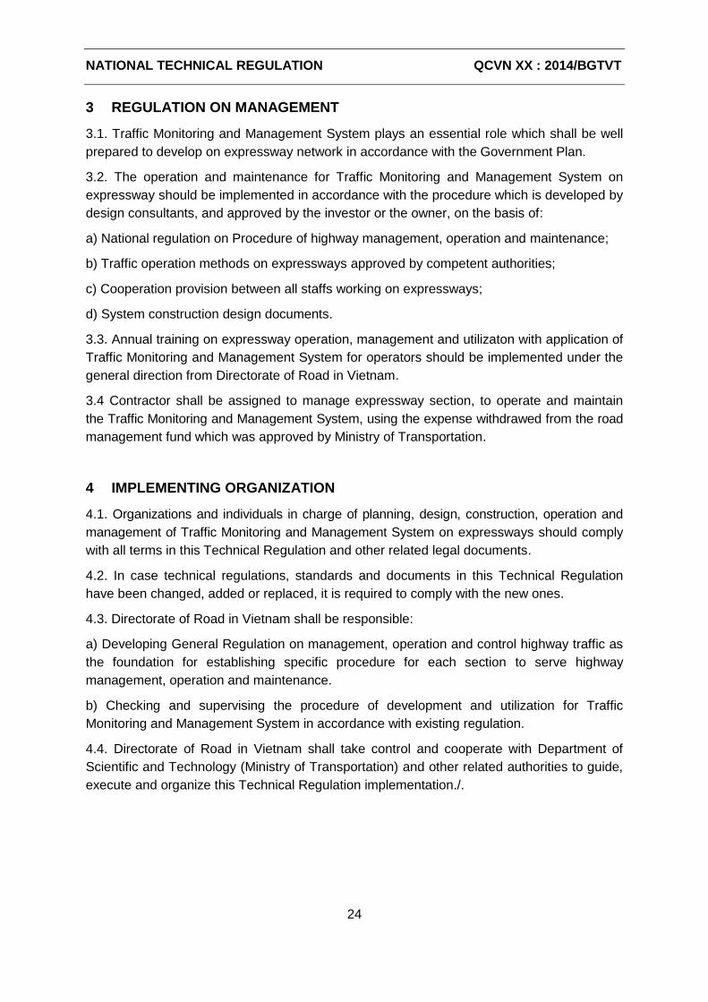
NATIONAL TECHNICAL REGULATION QCVN XX : 2014/BGTVT
24
3 REGULATION ON MANAGEMENT
3.1. Traffic Monitoring and Management System plays an essential role which shall be well
prepared to develop on expressway network in accordance with the Government Plan.
3.2. The operation and maintenance for Traffic Monitoring and Management System on
expressway should be implemented in accordance with the procedure which is developed by
design consultants, and approved by the investor or the owner, on the basis of:
a) National regulation on Procedure of highway management, operation and maintenance;
b) Traffic operation methods on expressways approved by competent authorities;
c) Cooperation provision between all staffs working on expressways;
d) System construction design documents.
3.3. Annual training on expressway operation, management and utilizaton with application of
Traffic Monitoring and Management System for operators should be implemented under the
general direction from Directorate of Road in Vietnam.
3.4 Contractor shall be assigned to manage expressway section, to operate and maintain
the Traffic Monitoring and Management System, using the expense withdrawed from the road
management fund which was approved by Ministry of Transportation.
4 IMPLEMENTING ORGANIZATION
4.1. Organizations and individuals in charge of planning, design, construction, operation and
management of Traffic Monitoring and Management System on expressways should comply
with all terms in this Technical Regulation and other related legal documents.
4.2. In case technical regulations, standards and documents in this Technical Regulation
have been changed, added or replaced, it is required to comply with the new ones.
4.3. Directorate of Road in Vietnam shall be responsible:
a) Developing General Regulation on management, operation and control highway traffic as
the foundation for establishing specific procedure for each section to serve highway
management, operation and maintenance.
b) Checking and supervising the procedure of development and utilization for Traffic
Monitoring and Management System in accordance with existing regulation.
4.4. Directorate of Road in Vietnam shall take control and cooperate with Department of
Scientific and Technology (Ministry of Transportation) and other related authorities to guide,
execute and organize this Technical Regulation implementation./.
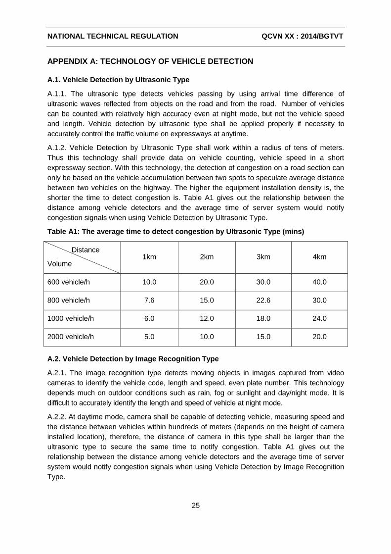
NATIONAL TECHNICAL REGULATION QCVN XX : 2014/BGTVT
25
APPENDIX A: TECHNOLOGY OF VEHICLE DETECTION
A.1. Vehicle Detection by Ultrasonic Type
A.1.1. The ultrasonic type detects vehicles passing by using arrival time difference of
ultrasonic waves reflected from objects on the road and from the road. Number of vehicles
can be counted with relatively high accuracy even at night mode, but not the vehicle speed
and length. Vehicle detection by ultrasonic type shall be applied properly if necessity to
accurately control the traffic volume on expressways at anytime.
A.1.2. Vehicle Detection by Ultrasonic Type shall work within a radius of tens of meters.
Thus this technology shall provide data on vehicle counting, vehicle speed in a short
expressway section. With this technology, the detection of congestion on a road section can
only be based on the vehicle accumulation between two spots to speculate average distance
between two vehicles on the highway. The higher the equipment installation density is, the
shorter the time to detect congestion is. Table A1 gives out the relationship between the
distance among vehicle detectors and the average time of server system would notify
congestion signals when using Vehicle Detection by Ultrasonic Type.
Table A1: The average time to detect congestion by Ultrasonic Type (mins)
Distance
Volume 1km 2km 3km 4km
600 vehicle/h 10.0 20.0 30.0 40.0
800 vehicle/h 7.6 15.0 22.6 30.0
1000 vehicle/h 6.0 12.0 18.0 24.0
2000 vehicle/h 5.0 10.0 15.0 20.0
A.2. Vehicle Detection by Image Recognition Type
A.2.1. The image recognition type detects moving objects in images captured from video
cameras to identify the vehicle code, length and speed, even plate number. This technology
depends much on outdoor conditions such as rain, fog or sunlight and day/night mode. It is
difficult to accurately identify the length and speed of vehicle at night mode.
A.2.2. At daytime mode, camera shall be capable of detecting vehicle, measuring speed and
the distance between vehicles within hundreds of meters (depends on the height of camera
installed location), therefore, the distance of camera in this type shall be larger than the
ultrasonic type to secure the same time to notify congestion. Table A1 gives out the
relationship between the distance among vehicle detectors and the average time of server
system would notify congestion signals when using Vehicle Detection by Image Recognition
Type.
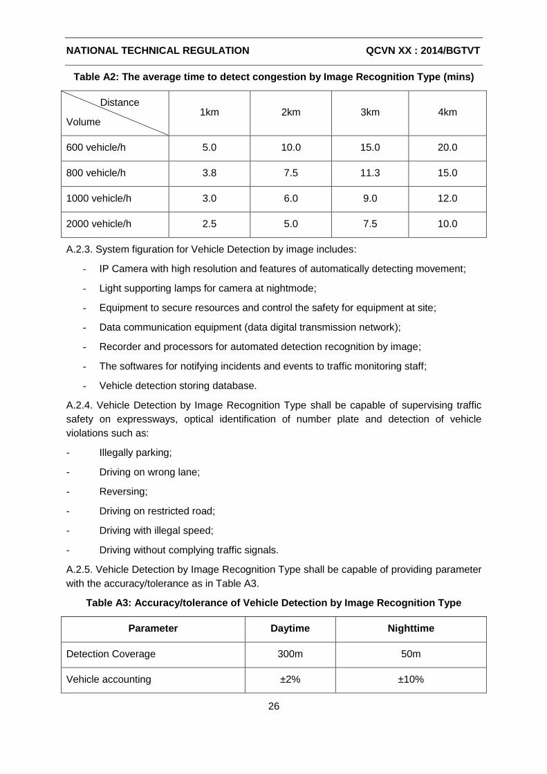
NATIONAL TECHNICAL REGULATION QCVN XX : 2014/BGTVT
26
Table A2: The average time to detect congestion by Image Recognition Type (mins)
Distance
Volume 1km 2km 3km 4km
600 vehicle/h 5.0 10.0 15.0 20.0
800 vehicle/h 3.8 7.5 11.3 15.0
1000 vehicle/h 3.0 6.0 9.0 12.0
2000 vehicle/h 2.5 5.0 7.5 10.0
A.2.3. System figuration for Vehicle Detection by image includes:
- IP Camera with high resolution and features of automatically detecting movement;
- Light supporting lamps for camera at nightmode;
- Equipment to secure resources and control the safety for equipment at site;
- Data communication equipment (data digital transmission network);
- Recorder and processors for automated detection recognition by image;
- The softwares for notifying incidents and events to traffic monitoring staff;
- Vehicle detection storing database.
A.2.4. Vehicle Detection by Image Recognition Type shall be capable of supervising traffic
safety on expressways, optical identification of number plate and detection of vehicle
violations such as:
- Illegally parking;
- Driving on wrong lane;
- Reversing;
- Driving on restricted road;
- Driving with illegal speed;
- Driving without complying traffic signals.
A.2.5. Vehicle Detection by Image Recognition Type shall be capable of providing parameter
with the accuracy/tolerance as in Table A3.
Table A3: Accuracy/tolerance of Vehicle Detection by Image Recognition Type
Parameter Daytime Nighttime
Detection Coverage 300m 50m
Vehicle accounting ±2% ±10%
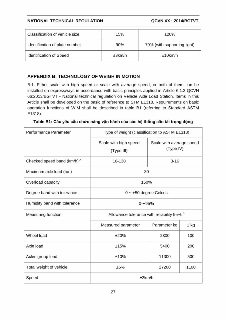
NATIONAL TECHNICAL REGULATION QCVN XX : 2014/BGTVT
27
Classification of vehicle size ±5% ±20%
Identification of plate numbet 90% 70% (with supporting light)
Identification of Speed ±3km/h ±10km/h
APPENDIX B: TECHNOLOGY OF WEIGH IN MOTION
B.1. Either scale with high speed or scale with average speed, or both of them can be
installed on expressways in accordance with basic principles applied in Article 6.1.2 QCVN
66:2013/BGTVT - National technical regulation on Vehicle Axle Load Station. Items in this
Article shall be developed on the basic of reference to STM E1318. Requirements on basic
operation functions of WIM shall be described in table B1 (referring to Standard ASTM
E1318).
Table B1: Các yêu cầu chức năng vận hành của các hệ thống cân tải trọng động
Performance Parameter Type of weight (classification to ASTM E1318)
Scale with high speed
(Type III)
Scale with average speed
(Type IV)
Checked speed band (km/h) A 16-130 3-16
Maximum axle load (ton) 30
Overload capacity 150%
Degree band with tolerance 0 ~ +50 degree Celcus
Humidity band with tolerance 0~95%
Measuring function Allowance tolerance with reliability 95% B
Measured parameter Parameter kg ± kg
Wheel load ±20% 2300 100
Axle load ±15% 5400 200
Axles group load ±10% 11300 500
Total weight of vehicle ±6% 27200 1100
Speed ±2km/h
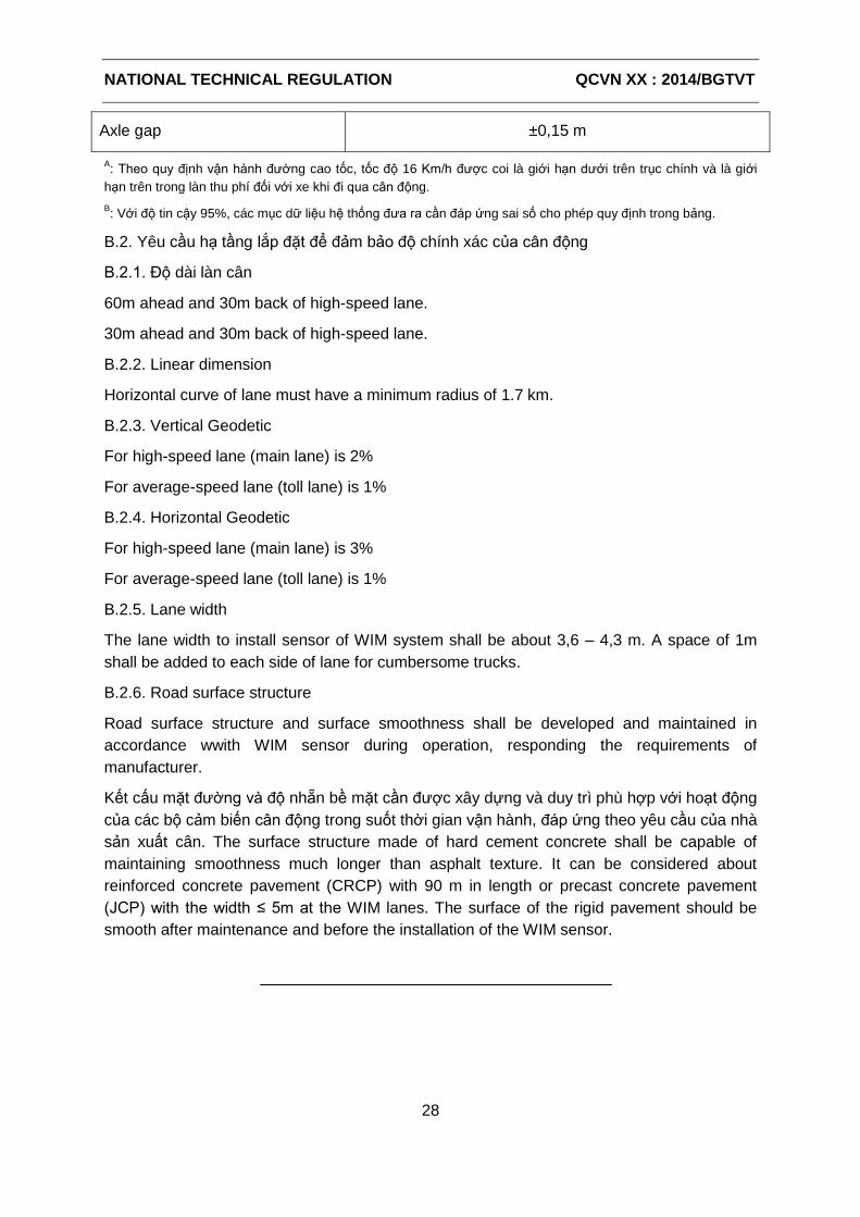
NATIONAL TECHNICAL REGULATION QCVN XX : 2014/BGTVT
28
Axle gap ±0,15 m
A: Theo quy định vận hành đường cao tốc, tốc độ 16 Km/h được coi là giới hạn dưới trên trục chính và là giới
hạn trên trong làn thu phí đối với xe khi đi qua cân động.
B: Với độ tin cậy 95%, các mục dữ liệu hệ thống đưa ra cần đáp ứng sai số cho phép quy định trong bảng.
B.2. Yêu cầu hạ tầng lắp đặt để đảm bảo độ chính xác của cân động
B.2.1. Độ dài làn cân
60m ahead and 30m back of high-speed lane.
30m ahead and 30m back of high-speed lane.
B.2.2. Linear dimension
Horizontal curve of lane must have a minimum radius of 1.7 km.
B.2.3. Vertical Geodetic
For high-speed lane (main lane) is 2%
For average-speed lane (toll lane) is 1%
B.2.4. Horizontal Geodetic
For high-speed lane (main lane) is 3%
For average-speed lane (toll lane) is 1%
B.2.5. Lane width
The lane width to install sensor of WIM system shall be about 3,6 – 4,3 m. A space of 1m
shall be added to each side of lane for cumbersome trucks.
B.2.6. Road surface structure
Road surface structure and surface smoothness shall be developed and maintained in
accordance wwith WIM sensor during operation, responding the requirements of
manufacturer.
Kết cấu mặt đường và độ nhẵn bề mặt cần được xây dựng và duy trì phù hợp với hoạt động
của các bộ cảm biến cân động trong suốt thời gian vận hành, đáp ứng theo yêu cầu của nhà
sản xuất cân. The surface structure made of hard cement concrete shall be capable of
maintaining smoothness much longer than asphalt texture. It can be considered about
reinforced concrete pavement (CRCP) with 90 m in length or precast concrete pavement
(JCP) with the width ≤ 5m at the WIM lanes. The surface of the rigid pavement should be
smooth after maintenance and before the installation of the WIM sensor.
添付資料-4
DRAFT QCVN OF
CCTV CAMERA SYSTEM FOR EXPRESSWAYS
( SUB-GROUP 4 )
SOCIALIST REPUBLIC OF VIETNAM
QCVN XX : 2014/BGTVT
NATIONAL TECHNICAL REGULATION ON HIGHWAY CAMERA MONITORING SYSTEM
Hệ thống Camera Giám sát Giao thông trên Đường Cao tốc
HA NOI - 2014
1ST DRAFT
(Sub-Group 4)
2014.02.07
NATIONAL TECHNICAL REGULATION QCVN XX : 2014/BGTVT
1
Foreword
QCVN XX : 2014/BGTVT was compiled by Drafting Board for National Technical Regulation on
Highway Camera Monitoring System under the Information Technology Center, Ministry of
Transportation, approved by Department of Science Technology and issued in accordance with
Circular No. ...../2014/TT – BGTVT on …………, 2014 by the Minister of MOT.
1ST DRAFT
(Sub-Group 4)
2014.02.07
NATIONAL TECHNICAL REGULATION QCVN XX : 2014/BGTVT
2
NATIONAL TECHNICAL REGULATION ON HIGHWAY CAMERA MONITORING SYSTEM Quy chuẩn Kỹ thuật Quốc gia về Hệ thống Camera Giám sát Giao thông
trên Đường cao tốc
1 General Regulation .............................................................................................. 3
1.1 Scope .................................................................................................................... 3
1.2 Application Objects .............................................................................................. 3
1.3 Terminology and Definition ................................................................................. 3
1.4 Abbreviations ....................................................................................................... 3
2 General Requirements on System ....................................................................... 5
3 System Architecture ............................................................................................. 5
4 Roadside Camera System ..................................................................................... 6
4.1 Requirements on Function .................................................................................. 6
4.2 Structure .............................................................................................................. 7
4.3 Technical Requirements ...................................................................................... 7
4.4 Human-Machine Interfaces ................................................................................. 8
4.5 Installation ........................................................................................................... 9
5 Network Video Recorder (NVR) ......................................................................... 10
6 Video Image Displaying Device .......................................................................... 11
7 Image Transmitter.............................................................................................. 12
8 Central CCTV Controller ..................................................................................... 12
8.1 Function ............................................................................................................. 12
8.2 Structure ............................................................................................................ 13
8.3 Performance ...................................................................................................... 13
8.4 Human-Machine Interfaces ............................................................................... 13
8.5 Communication Interfaces ................................................................................. 13
8.6 Installation ......................................................................................................... 15
9 Moniroting Camera Controller .......................................................................... 14
9.1 Function ............................................................................................................. 14
9.2 Structure ............................................................................................................ 14
9.3 Performance ...................................................................................................... 14
9.4 Human-Machine Interfaces ............................................................................... 15
9.5 Communication Interfaces ................................................................................. 15
9.6 Installation ......................................................................................................... 15
10 Ambient Conditions ........................................................................................... 15
11 Power Supply ..................................................................................................... 16
12 Maintenance ...................................................................................................... 16
13 Regulation on Management .............................................................................. 16
14 Implementing Organization ............................................................................... 17
NATIONAL TECHNICAL REGULATION QCVN XX : 2014/BGTVT
3
1 General Regulation
1.1 Scope
This technical regulation provides basic requirements on equipment components,
performance and interface of Cameras installed on expressways which help operators in
monitoring highway traffic activities such as: traffic accident, broken-down vehicle, left
obstacle, reversing vehicle, vandalism, natural disaster and expressway conditions.
1.2 Application Objects
This regulation shall be applied to any organizations and individuals in charge of planning,
design, construction and operation of highway camera monitoring systems.
1.3 Terminology and Definition
Road Management Office: is under management of contractor to monitor and control traffic
on Expressways. This office shall be operated along with support from automatic technology,
communication and control equipments in the investment package for traffic monitoring
and management system.
Regional Main Center: is responsible for monitoring, managing Road Management Offices
within jurisdiction. Regional Main Center can connect to Road Management Offices by using
Intelligent Transportation System – ITS.
Operator: is the person securing the operation of Intelligent Transportation System ITS at
both Road Management Office and Regional Main Center.
Traffic Event: is the situation affecting to traffic condition included traffic incidents,
dangerous weather, traffic congestion, construction work, violation of drivers, traffic
restrictions and other special events.
Incident: is the unusual event without in advance affecting or interrupting traffic condition
included traffic accidents, broken-down vehicles, obstacles on road or natural disasters.
Station: is the area in where operation centers of tollgate, rest area and service on route
locate.
Camera IP: the digital camera which is capable of transceiving and encoding images, then
transmitting signals over IP/Ethernet protocol network.
Network Video Recorder (NVR): Network Video Recorder – Digital image capturing
equipment for IP camera system.
Power over Ethernet (PoE): is the method of supplying one-way power at low voltage over
the shared Ethernet network cable connected to equipment.
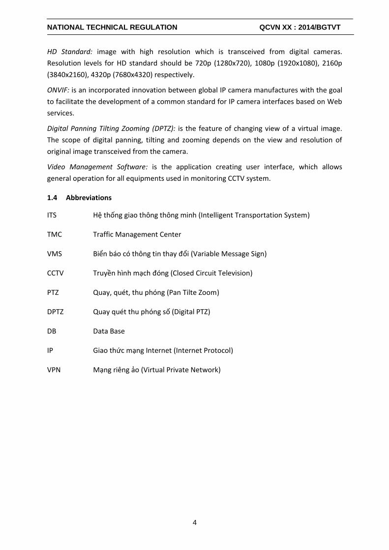
NATIONAL TECHNICAL REGULATION QCVN XX : 2014/BGTVT
4
HD Standard: image with high resolution which is transceived from digital cameras.
Resolution levels for HD standard should be 720p (1280x720), 1080p (1920x1080), 2160p
(3840x2160), 4320p (7680x4320) respectively.
ONVIF: is an incorporated innovation between global IP camera manufactures with the goal
to facilitate the development of a common standard for IP camera interfaces based on Web
services.
Digital Panning Tilting Zooming (DPTZ): is the feature of changing view of a virtual image.
The scope of digital panning, tilting and zooming depends on the view and resolution of
original image transceived from the camera.
Video Management Software: is the application creating user interface, which allows
general operation for all equipments used in monitoring CCTV system.
1.4 Abbreviations
ITS Hệ thống giao thông thông minh (Intelligent Transportation System)
TMC Traffic Management Center
VMS Biển báo có thông tin thay đổi (Variable Message Sign)
CCTV Truyền hình mạch đóng (Closed Circuit Television)
PTZ Quay, quét, thu phóng (Pan Tilte Zoom)
DPTZ Quay quét thu phóng số (Digital PTZ)
DB Data Base
IP Giao thức mạng Internet (Internet Protocol)
VPN Mạng riêng ảo (Virtual Private Network)
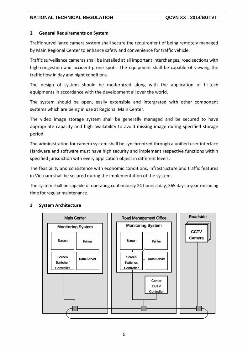
NATIONAL TECHNICAL REGULATION QCVN XX : 2014/BGTVT
5
2 General Requirements on System
Traffic surveillance camera system shall secure the requirement of being remotely managed
by Main Regional Center to enhance safety and convenience for traffic vehicle.
Traffic surveillance cameras shall be installed at all important interchanges, road sections with
high-congestion and accident-prone spots. The equipment shall be capable of viewing the
traffic flow in day and night conditions.
The design of system should be modernized along with the application of hi-tech
equipments in accordance with the development all over the world.
The system should be open, easily extensible and intergrated with other component
systems which are being in use at Regional Main Center.
The video image storage system shall be generally managed and be secured to have
appropriate capacity and high availability to avoid missing image during specified storage
period.
The administration for camera system shall be synchronized through a unified user interface.
Hardware and software must have high security and implement respective functions within
specified jurisdiction with every application object in different levels.
The feasibility and consistence with economic conditions, infrastructure and traffic features
in Vietnam shall be secured during the implementation of the system.
The system shall be capable of operating continuously 24 hours a day, 365 days a year excluding
time for regular maintenance.
3 System Architecture
Roadside Main Center
Road Management Office
CCTV
Camera
Monitoring System
Monitoring System
Screen
Printer
Screen
Switcher/
Controller
Data Server
Screen
Printer
Screen
Switcher/
Controller
Data Server
Center
CCTV
Controller
NATIONAL TECHNICAL REGULATION QCVN XX : 2014/BGTVT
6
Figure: Highway Camera Monitoring System Architecture
System Architecture includes 3 main factors:
- CCTV system and other supporting devices shall be installed on expressways for monitoring
highway incidents and events.
- Controller system at Road management office shall be applied for monitoring and
controlling CCTV system within jurisdiction of the office.
- Controller system at Regional Main Center shall be applied for monitoring and controlling
CCTV system within jurisdiction of the center.
4 Roadside Camera System
4.1 Requirements on Function
Traffic monitoring cameras shall be installed on roadside under outdoor conditions to
transceive images monitoring traffic vehicle flows. Capturing images from cameras should
be black/white or colour images.
Cameras shall be capable of working continuously 24 hours a day, 36 days a year excluding
time for regular maintenance. Transceived images could be clearly monitored with or
without light supporting equipment at anytime.
Depending on capability of controlling surveillance angle, CCTV Cameras shall be devided
into two types:
Camera allows adjusting the viewing angle as remote requirement by panning, tilting
and zooming the lens. PTZ camera shall be usually installed at interchanges or road sections
with large range of observation in different directions from near to far distance.
+ Fixed camera shall allow surveilling with a single angle at the initial installation place.
The camera shall be commonly used to monitor on the road section with fixed view
according to the direction of vehicle flow.
Digital cameras with high-resolution images in accordance with HD standard shall be
selected to install. Each camera shall be identified by an IP address in the connection
network.
The cameras shall be supported with the intelligent processing feature to secure good image
quality and adapt to operation conditions such as the change of light, the shaking of camera
by strong wind.
After operation recovery from the power failure, to automatically switch on the equipment
components and the software.
NATIONAL TECHNICAL REGULATION QCVN XX : 2014/BGTVT
7
4.2 Structure
The equipment components shall have adequate structure, shape, size, lightweight and
robustness. The components shall be protected with the measures against typhoon, fire,
earthquake, sandstorm and lightning.
The equipment components shall be protected with the measures against water, rust, dust, salt
water in case equipment components are installed outdoors.
The chassis of equipment components shall have adequate structure which allows maintenance
works from the sides and/or back, but not from lane direction, in order to minimize the
influence to traffic activities on lanes.
The Chassis of equipment shall be capable of dissipating temperature rising from inside
equipment and radiant solar heat.
The equipment components shall be protected with the measures against interference from
other electronic devices.
CCTV camera shall be protected against dust and water ingress if it will be installed outdoors
(excluding tunnels) in accordance with IP66 of the international standards IEC 60529 or
equivalent.
The system shall be capable of fully meeting the requirements even under night conditions.
4.3 Technical Requirements
IP Camera for traffic monitoring shall be required to achieve minimum general specifications
as follows:
a) CCTV camera shall be capable of surveilling in day mode and night mode with the
minimum illumination of 0.5 lux.
b) The minimum resolution under HD Standard for images shall be 720p (1280x720)
and 25fps.
c) CCTV camera shall provide output monitoring video flow which is capable of
encoding images in H.264 and Motion JPEG.
d) CCTV camera shall have the focal length of lens in accordance with surveilling angle,
the width of sensor reaches a minimum of a quarter;
e) CCTV camera can autofocus image;
f) CCTV camera shall be capable of manually controlling and automatic aperture to
match the brightness of the object for the best video image.
g) CCTV camera shall have functions of automatically processing the transceived
images such as auto gain control (kiểm tra độ lợi sáng), auto white balance (cân
bằng ánh sáng trắng) and backlight compension (bù ánh sáng ngược);
NATIONAL TECHNICAL REGULATION QCVN XX : 2014/BGTVT
8
h) CCTV camera shall be protected by the chassis to prevent rain/sunlight and dust, in
accordance with IP66 at least;
i) CCTV camera can operate stably in Vietnam ambient conditions: at -15 to 50 degrees
with humidity range from 20 to 90%.
PTZ cameras shall have dome structure (dạng vòm). The specifications should be required as
follows
a) CCTV camera must be capable of panning at least 350 degrees and tilting 100 degrees;
b) The minimum optical PTZ of camera must be at x10 times
c) The maximum surveillance range of camera must be greater than 1000m
The fixed IP cameras with resolution ≥ 1080p (1920x1080) shall function creating virtual
images so that user can simultaneously monitor different locations in the camera frame.
User can function digital panning, tilting and zooming (DPTZ) on each created virtual image.
IP camera shall be used to support the installation of intelligent features such as
automatically detecting image motion, warning blurred or obscured images. A signal
gateway shall be prepared for warning from camera.
The camera shall use the power supply over Ethernet network cable (PoE). The equipment
shall have the feature of saving energy and consume power less than 50W to fixed camera,
100W to PTZ camera.
The camera should provide an interface to configure and view online images on Web. The
equipments at center shall be capable of remotely control camera over IP network
according to ONVIF standard.
The camera location shall be selected to secure traffic monitoring at the highest
effectiveness, to avoid being out of sight in curves or construction works; with the aim of
minimizing blind spots on road sections.
Depending on the construction site of the installation location, the camera can be installed
on brackets, on roadside pole with or without handgrip. The installation height of camera
must secure the minimum safety space in road traffic.
The installation structure for roadside cameras shall be designed with the measures against
straight lightning and strong wind at 40mps or equivalent.
4.4 Human-Machine Interfaces
CCTV camera shall have the function to output test image to personal computers at site so that
installation staff may adjust the direction of CCTV camera.
The system shall have video image output interface to adjust angle of view of camera and
receiving control signal interface to check camera operation at installation at installation site.
NATIONAL TECHNICAL REGULATION QCVN XX : 2014/BGTVT
9
4.5 Installation
CCTV camera installation has the following general requirement:
Roadside equipment shall be installed so as not to obstruct the vertical clearance on expressways.
CCTV camera installed at Toll Island in where the camera can capture the front of vehicle
(including license plate).
Horizontal and vertical angle of CCTV camera shall be capable of being adjusted and fixed
appropriately at the installation site.
CCTV camera shall be capable of being vertically and horizontally adjusted during installation at
roadside.
The equipment components shall have adequate robustness against the wind of speed according
to TCVN 2737:1995.
CCTV camera shall be installed so that images may not swing by strong wind.
CCTV camera shall be installed so that images may not swing by strong wind. In case the
equipments to be located at outdoor, the screw for attachment should be antitheft type.
In case the equipments to be located at outdoor, the screw for attachment should be antitheft
type.
CCTV camera with panning, tilting and zooming functions shall be installed at intervals of 2 km or
less along through lanes so as to monitor situations such as incidents, broken vehicles, traffic
congestions, and bad weather through day and night.
One or two fixed CCTV cameras shall be installed on the ramp so as to monitor situations such as
incidents, broken vehicles, traffic congestions, and bad weather through day and night.
CCTV cameras shall be installed so as to get images of the road within one kilometer range
without influence of obstacles such as plane curve, longitudinal slope, roadside cutting slope,
overbridges, buildings, trees, lighting poles, traffic signs, and VMS.
CCTV camera shall be installed so that images may not swing by strong wind.
In case of more than one camera are attached on the same pole, each camera shall be attached
with at least 1m height interval.
The angle of view of a camera shall be adjusted for monitoring the road continuously in
consideration of the field of investigation.
In case the equipments to be located at outdoor, the screw for attachment should be antitheft
type.
CCTV camera installation is divided into three categories:
NATIONAL TECHNICAL REGULATION QCVN XX : 2014/BGTVT
10
- Installation of PTZ type camera on through lanes: should be installed along the expressway at
least every 2km as follows:
+ One PTZ type camera for monitoring inbound lane.
+ One PTZ type camera for monitoring outbound lane.
PTZ type camera need to be additionally installed In case of disrupting vision obstacles such
as flyover-bridge, longitudinal gradient of road, roadside cutting slope, tollgates, trees,
buildings or inquiring of many surveilling screens.
In ideal condition, PTZ type camera should be capable of monitoring the road continuously.
- Installation of PTZ type camera for monitoring junction/interchange including tollgate.
PTZ type cameras should be installed according to junction and interchange type. Each type
requires different PTZ camera location to monitor the whole area.
In ideal condition, PTZ type camera should be capable of monitoring junction/interchange
including tollgate.
- Installation of Fixed type camera on ramp.
Fixed type camera should be installed to monitor each ramp of the junction or interchange.
Fixed type cameras shall be installed attached on roadside around the diverging/merging point of
ramp with the maximum surveillance area possible.
Fixed type camera should be installed 6-7m above ground level in accordance with the limit
construction clearance in accordance with TCVN 4054:2005 and TCVN 5729.
Fixed type camera need to be installed in case of disrupting vision obstacles such as flyover
bridge, longitudinal gradient of road, roadside cutting slope, overbridges, buildings, trees, lighting
poles, traffic signs, VMS, alignment of road, tollgate, etc.
5 Network Video Recorder (NVR)
Video images from IP cameras shall be transmitted to Network Video Recorder (NVR) in
order to store for searching and reviewing as request of users.
NVR used in traffic monitoring system shall have minimum functions as follows:
a) Recording images as video data file with H264 encoding standard
b) Recording images along with multi video streams in the same connection network
c) Managing the continuous recording, fixed time recording or preset recording as the
activation of external events.
d) Replaying video images recorded in different time on IP network in accordance with
RTSP protocol, and quickly searching an image recorded at random time
NATIONAL TECHNICAL REGULATION QCVN XX : 2014/BGTVT
11
e) Shifting video images recorded from cameras at being time
f) Managing storage capacity of each camera, of automatically organizing old video
data for recording new data
g) Automatically controlling and warning on recording errors, loss of image signal,
storage disk or full limit.
Many NVR equipments can be operated at the same time to assign the video data storage
capacity for a large number of cameras. The parallel equipment shall be capable of taking a
role of backup device which can replace the main one in case of errors. The management for
balancing the number of recording camera in NVR equipment shall be automatically done by
Network Video Management Software.
Besides the function of storing, recording equipments shall be capable of integrating or
extending intelligent functions of processing images for traffic management such as traffic
volume measurement, event detection and vehicle identification by video image.
6 Video Image Displaying Device
The images of all traffic surveillance cameras shall be managed on monitoring screen of
each operator and large wall screen (if any) at management office.
In case the number of monitoring cameras is larger than the installed screens, image
displaying equipment shall be capable of organizing as follows:
a) Multi images of different cameras shall be separately displayed on the splitting
window Screen as a matrix form.
b) Images of cameras in group shall be displayed on the same Monitor Screen in defined
rotating interval.
For PTZ cameras, displaying equipment at operator position shall be installed with dedicated
camera controller or computer software. The camera should be setup with preset angles so
that user can quickly adjust camera to special locations or to automatically control the
camera at different locations in cyclical time.
Image displaying wall screen shall be applied with the technology of combining multiple
physical screens to a large wall screen or dividing into multiple virtual screens. Video images
from cameras shall be controlled to display on virtual screen of wall screen.
The remote controller of wall screen shall be used to function the following tasks:
a) The equipment shall be capable of organizing matrix on virtual screen which is
displayed on wall screen;
b) The equipment shall be capable of setting the content to display on each virtual
screen including video image from camera and interface of application software;
NATIONAL TECHNICAL REGULATION QCVN XX : 2014/BGTVT
12
c) The equipment shall be capable of storing common configuration to quickly shift the
content displayed on wall screen to different views;
d) The equipment shall be capable of managing timing schedule with preset contents
displayed on wall screen.
7 Image Transmitter Equipment
Image transmission network for traffic monitoring camera system shall secure the
transmission bandwidth of at least one video stream from each IP camera to center with HD
720p resolution.
The accessing equipment for radio transmission network shall meet the following
requirement on specifications:
a) The frequency range 2400 ÷ 2483.5 Mhz, 5150 ÷ 5350 Mhz, 5470 ÷ 5725 Mhz, 5725 ÷
5850 Mhz
b) The minimum channel width 20 MHz, the minimum channel distance 10 MHz
c) The transceiving distance between camera and base station ≤ 20 km, between the
two 2 base stations ≤ 30 km
d) The transmission speed from camera to base station 04 Mbps, and between the two
base stations 100 Mbps
e) Transmission protocol Ethernet/IP
Switching equipment component for wire network using optic cable shall meet the following
requirement on specifications:
a) The architecture for network design shall include 3 layers: core network, external
network, accessing network
b) The transmission speed in core network 10 Gbps, external network 1000 Mbps,
accessing network 100 Mbps
c) The distance among nodes in core network ≤ 40km, external network ≤ 10km,
accessing network ≤ 2km
d) Transmission protocol Ethernet/IP
8 Central CCTV Controller
8.1 Function
The central CCTV controller shall be capable of controlling CCTV cameras functions such as
zooming, panning and tilting.
NATIONAL TECHNICAL REGULATION QCVN XX : 2014/BGTVT
13
The CCTV camera shall be capable of being controlled from Regional Main Center or Road
Management Office depending on the given.
8.2 Structure
The equipment components shall have adequate structure, shape, size, lightweight and
robustness; be be protected with the measures against lightning.
Chassis of equipment shall be capable of dissipating temperature rising from inside equipment.
The equipment components shall be protected with the measures against interference from
other electronic devices.
8.3 Performance
The function of encoding data of central CCTV controller complies with H.264, MPEG-4 Part 2.
The central CCTV controller shall operate with less than 6Mbps bit rate and over 25 fps frame
rate.
The central CCTV controller may have recording unit with: At least 1 mega pixel resolution; more
than 1 fps frame rate. This unit should be capable of recording continuously 24 hours.
8.4 Human-Machine Interfaces
Operators shall use CCTV monitoring console for setting the functions of Central CCTV Controller.
The operators at the Regional Main Center and Road Management Offices shall use
keyboards and joysticks to function panning, tilting and zooming of cameras to monitor the
images taken by CCTV cameras
The system shall be equipped with the functions so that operator sitting at the console 5m away
from the main screen at Regional Main Center may confirm such situations as incidents, broken
vehicles, traffic congestions, and bad weathers on the expressways through day and night by
indicating images taken by CCTV cameras on the main screen of Regional Main Center.
8.5 Communication Interfaces
The system shall be capable of controlling the signal for images transmitted over TCP/IP.
The system shall have 100BASE, 1GBASE Ethernet and RJ-45 connectors.
The system shall be capable of working with Ethernet protocols such as: IP, UDP, RTP, multicast
The following information shall be disclosed for communication interfaces among the
equipment components to control CCTV and accessible to CCTV video images from another
equipment / console:
- The name of implementation software
- Bit allocation, which is needed for designing data transmission between transmission devices
NATIONAL TECHNICAL REGULATION QCVN XX : 2014/BGTVT
14
- Transmission data format
- Timing chart and other details of the standard interfaces
Necessary information or specification of equipment components shall be capable of being
disclosed in order to secure the interoperability of devices.
8.6 Installation
The equipment of components shall be installed at Road Management Offices.
Software shall be capable of being installed on an operating system such as Microsoft
Windows or Linux.
The total number of equipments depends on the number of cameras and the number of
interfaces on equipment.
9 CCTV Monitoring Console
9.1 Function
The system shall be controlled remotely by using such equipments as joystick, keyboard, trackball
in the Regional Main Center. CCTV camera control shall be conducted using IP address
corresponding to CCTV camera identification number.
9.2 Structure
The equipment components shall have adequate structure, shape, size, lightweight and
robustness.
The equipment components shall be protected with the measures against lightning.
The chassis of equipment components which is capable of dissipating temperature arising from
inside equipment, shall not be opened easily, and its door shall be opened/closed with a lock.
The equipment components shall be protected with the measures against interference from
other electronic devices.
9.3 Performance
The system shall be capable of controlling the zooming and horizontally/vertically panning
functions of cameras.
The system shall be capable of displaying the selected camera image on the designated monitor
screen.
Recommended size of monitor screen shall be at least 20 inches.
All camera images shall be capable of being displayed on Monitor Screen. In case the number of
cameras is more than which of screens, it should be organized as follows:
NATIONAL TECHNICAL REGULATION QCVN XX : 2014/BGTVT
15
- Multi images shall be separately displayed on the same Monitor Screen.
- Images shall be displayed on the same Monitor Screen in defined rotating interval.
The system shall be capable of capturing CCTV images as still pictures.
9.4 Human-Machine Interfaces
The equipment components shall have human-machine interface such as keyboard, joystick, or
track ball, so that the Traffic Information Operator can operate CCTV camera system.
The system shall be capable of printing captured still pictures by using A4 printer.
The monitor in the console shall be greater than 20 inches so that operators at Regional Main
Center and Road Maintenance Office may confirm incidents, broken vehicles, traffic congestions,
and bad weathers on the expressways through day and night by indicating images taken by CCTV
cameras on the main screen.
9.5 Communication Interfaces
The system shall be capable of controlling the signal for images transmitted over TCP/IP.
The equipment components shall have the following communication interfaces and information
in order to ensure that equipment components are controllable by CCTV, and accessible to CCTV
video images from another equipment / console.
- The name of implementation software
- Bit allocation, which is needed for designing data transmission between transmission devices
- Transmission data format
- Timing chart and other details of the standard interfaces
Necessary information or specification of equipment components shall be capable of being
disclosed in order to secure the interoperability of devices.
9.6 Installation
The equipment shall be installed in Road Management Offices and Regional Main Center.
Software shall be capable of being installed on the operating system such as Microsoft Windows
or Linux.
10 Ambient Conditions
The equipment components shall be installed in the offices and protected by the measures
against interferences of other electronic devices.
The equipment component shall be capable of normally operating under the following ambient
conditions:
NATIONAL TECHNICAL REGULATION QCVN XX : 2014/BGTVT
16
For Regional Main Center, Toll Management Center, and Toll Office
Temperature: 25 +/- 3 degree C in average
Relative humidity: between 20 and 80 % in average
For outside
Temperature: between - 0 and +50 degree C
Relative humidity: below 95 %
11 Power Supply
The main power supply shall be AC 220 volts single phase and 50 Hz frequency.
System shall have Uninterrupted Power Supply (UPS) against power failure. UPS must be capable
of providing power for the system for at least 30 minutes.
12 Maintenance
The system shall be capable of being checked and maintained easily and simply.
The system shall be capable of identifying faulty parts easily in case equipment fault is detected,
and the replacement of the parts shall be simple.
The spare parts of the equipment components shall be available at least five (5) years after the
equipment component is handed over to the road management authority, and the manufacturer
shall guarantee this spare parts supply period.
13 Regulation on Management
Traffic Monitoring System takes an essential part which should be invested in the projects of
developing ITS on expressway
The operation and maintenance for Highway Camera Monitoring System should be
implemented in accordance with the procedure which is approved by Ministry of
Transportation or the investor on the basis of:
- Government Regulation on highway management, utilization and maintenance;
- Traffic arrangement plan for expressways has been approved by competent authorities;
- Cooperation provision between all staffs working on expressways;
Contractor shall be assigned to manage expressway section, to operate and maintain the
Traffic Monitoring and Management System, using the expense withdrawed from the road
management fund which was approved by Ministry of Transportation.
NATIONAL TECHNICAL REGULATION QCVN XX : 2014/BGTVT
17
14 Implementing Organization
Organizations and individuals in charge of planning, design, construction, operation and
management of Traffic Monitoring and Management System on expressways should comply
with all terms in this Technical Regulation and other related legal documents.
In case technical regulations, standards and documents in this Technical Regulation have
been changed, added or replaced, it is required to compyly with the new ones.
Directorate of Road in Vietnam shall be responsible for:
- Developing provisions on cooperating, utilizing and applying Intelligent Trasportation
System – ITS included Traffic Monitor and Management System into expressway operation,
management and maintenance.
- Inspecting, surveilling the process of investing, building and utilizing Traffic Monitoring and
Management Systems in accordance with regulated provisions.
Directorate of Road in Vietnam shall take control and cooperate with Department of
Scientific and Technology (Ministry of Transportation) and other related authorities to guide,
execute and organize this Technical Regulation implementation./.
添付資料-5
DRAFT QCVN OF
VMS SYSTEM FOR EXPRESSWAYS ( SUB-GROUP 5 )
MINISTRY OF TRANSPORT
QUY CHUẨN KỸ THUẬT QUỐC GIA
VỀ BIỂN BÁO GIAO THÔNG ĐIỆN TỬ
TRÊN ĐƯỜNG CAO TỐC
National Technical Regulation on Electronic Signs
on Expressway
QC13315
Chair agency: Institute of Transport Science and Technology
Implementation unit: Center of Automation and Measurement
Compile head: M.A Nguyen Anh Tuan
Hanoi 01/2014
DRAFT 1
(Sub-Group 5)
2014.01.22
1
1 GENERAL REGULATION ............................................................................................. 2
1.1 Scope ..................................................................................................................... 2
1.2 Application Object ................................................................................................... 2
1.3 Abbreviations .......................................................................................................... 2
1.4 Terminology and Definition ..................................................................................... 2
2 TECHNICAL REGULATION .......................................................................................... 3
2.1 General regulation on Electronic signs on Expressway ........................................... 3
2.2 Material regulation .................................................................................................. 4
2.3 Shape and Size of Signs ......................................................................................... 5
2.4 Content Format on Signs ........................................................................................ 5
2.5 Font Size and Style ................................................................................................. 6
2.6 Color of Signs ......................................................................................................... 8
2.7 Brightness (Luminance) .........................................................................................10
2.8 Observation Feature ..............................................................................................10
2.9 Controller of Signs .................................................................................................10
2.10 Requirements on Power Supply and Related Problems .........................................11
2.11 Ambience ...............................................................................................................12
2.12 Checking and Maintenance ....................................................................................12
2.13 Label and Labeling .................................................................................................12
2.14 Installation..............................................................................................................13
3 REGULATION ON TEST AMD CHECK ........................................................................15
3.1 Testing/Checking Conditions .................................................................................15
3.2 External Check and Technical Check .....................................................................15
3.3 Power Supply and Related Issues .........................................................................15
3.4 Color Test and Check ............................................................................................16
3.5 Information Transmitting Inspection .......................................................................16
4 REGULATION ON MANAGEMENT ..............................................................................16
4.1 Management Principles..........................................................................................16
4.2 Regulation Conformation Certification and Announcement ...................................16
4.3 Responsibility of Road Management Agency .........................................................17
4.4 Responsibility of Road Users .................................................................................17
5 IMPLEMENTING ORGANIZATION ..............................................................................18
DRAFT 1
(Sub-Group 5)
2014.01.22
2
1. GENERAL REGULATION
1.1. Scope
1.1.1 This national technical regulation (hereinafter referred to as technical regulation)
regulates on electronic signs which are fixed installed on Expressway.
1.1.2 The electronic signs on Expressway are the electronic signs using illuminating LED to
show the content.
1.1.3 The electronicsigns which are fixed installed on Expressway are mentioned in this
technical regulation include: changeble information indicating Electronic signs (information
signs), changable speed limit electronic signs (speed limit signs).
The electronicwhich installed outside Expressway are recommended to apply this regulation.
1.1.4 The information shown on information signs is in two types: letters and figures.
1.2 Application Objects
This regulation applies to all organizations and individuals involved in the design,
construction, management, exploitation and maintenance of electronic signs on Expressway
in the whole country.
1.3 Abbreviations
ITS: Intelligent Transportation System
LED: Light Emitting Diode
ES (signs): Electronic signs
Exw: Expressway
1.4 Terminology and Definition
1.4.1 Electronic sign: is an electronic device providing instructions for traffic control, on
which displayed contents are changeable, provides traffic information for road users.
1.4.2 Traffic information: The information on speed limit, traffic jam, traffic accident,
maintenance, weather condition, road condition, event holding, or other expressway features
(road open/closure, tollgate, weight station...);
1.4.3 Traffic restriction: A means to restrict traffic on roads, such as road closure, lane
restriction, speed limit and warnings;
1.4.4 Incident: An unusual unpredictable event casing affect or inpede on traffic, for example
traffic accident, broken vehicle, obstacle, reversing vehicle, vandalism, unusual weather and
3
disaster on road.
1.4.5 Pixel: A basic unit of illuliminating display composed by one or more LEDs.
1.4.6 Pixel distance: the distance between 2 center points of 2 adjacent pixels.
1.4.7 Character width: is the distance measured from the center of the leftmost column and
outside right column of the matrix, in mm.
1.4.8 Character height: is the distance measured from the center of the top line and bottom
line of the matrix, in mm.
1.4.9 Brightness (luminance): concept of light that human eyes can observe at the area of
light or light source. Brightness (luminance) is measured by Candela per m2 (Cd/ m2);
1.4.10 Still observation distance: The maximum distance that the observer (normal person,
visual acuity is adjusted as 10/10 or more) when standing still can clearly read in daytime
condition;
1.4.11 Moving observation distance: The maximum distance that the observer (normal
person, visual acuity is adjusted as 10/10 or more) when moving in the speed of 120km/h can
clearly read in daytime condition;
1.4.12 Half-intensity angle: The angle of the fiber axis of the maximun intensity and the
fiber axis of half maximum intensity of LED.
2. TECHNICAL REGULATION
2.1 General regulation on Electronic Signs on Expressway
2.1.1 Signs are to be able to provide information in Vietnamese and English, the contents of
the information must be short, understandable, and suitable with the size of signs.
2.1.2 Signs are to be able to update information when it’s required to change the information
displayed from “traffic monitoring/control server”.
2.1.3 Content of displayed information on the surface: do not flicker, not the type of running
characters;
2.1.4 Signs are to be able to operate continuously, to ensure sufficient durability and
reliability in ambient conditions of the roadside installation;
2.1.5 Signs are to be protected by the prevention from big storm, fire, earthquake, sandstorm
and lightning, water, being rusted, dust, salt water, avoiding interference from other
electronic devices ...
4
2.2 Materials Requirement
2.2.1 Structure of signs
Signs include hard parts: display board, controller, frame, casing, connection gates,
connection parts,…Amongst, display board composes illuminating LED elements and
hanging frame.
2.2.2 Requirements on LED elements
2.2.2.1 Display board is composed by illuminating LEDs ensuring the requirements on color
defined in 2.6;
2.2.2.2 Information signs are to be made with couple modules, with the size of 8x16 or 16x32
pixels.
2.2.2.3 The LED to be selected are to ensure the uniform on color and brightness of signs;
LEDs when not illuminating is in black or no color;
2.2.2.4 The half-intensity angle is not less than 11,50;
2.2.2.5 Uniform illuminating: the ununiform in illuminating in the condition of rated operation
line of illuminating points on the whole sign and normal direction of the surface not more than
5%, in case that pixel includes many LEDs, the ununiform in illuminating in a pixel is not over
10%;
2.2.2.6 Stable average operation time of LED is not lower than 50000 hours. Stable average
operation time of other electronic components and devices is not lower than 30000 hours.
2.2.3 Signs’ casings
2.2.3.1 Signs and all structural assemblies, accessories are designed from sustainable
materials to ensure the best performance when long-term used in the actual atmospheric
conditions during normal long period in the places to use signs.
2.2.3.2 Signs’ casings and other parts of signs are to be completed, assembled closely,
structured stably, out holes of casing are to be suitable, neatly, outside angles and edges are
not is not sharp or caused to stand out., the connection between out line and the case is to
be close and tight;
2.2.3.3 Signs’ casings are to be designed to adjust observation angle for signs;
2.2.3.4 Signs’ casings are to have suitable structure for not being easily opened and the caps
are to be locked.
5
2.3 Shape and Size of Signs
2.3.1 Information signs
2.3.1.1 In case information displayed is in characters, using the following to decide the shape
and size of information signs:
+ contents of data message defined in National Regulations on data message system
on expressway.
+ The method for presenting the displayed content on signed is defined in 2.4.1 for
information signs of characters;
+ Font Size and Style are defined in 2.5.1 for information signs.
2.3.1.2 In case information displayed is in figures, information signs are to be in suitable
shape and size with figures needed to be displayed which is defined in 22TCN 331-05 and
observation distance is defined in 2.8;
2.3.1.3 The thickness of information signs are to be designed in accordance with its size.
2.3.2 Speed Limit Signs
2.3.2.1 Speed limit signs are to be in suitable shape and size for the display board to display
outside edge circle of LED edge of 1200mm diameter;
2.3.2.2 The thickness of speed limit signs are to be designed in accordance with its size.
2.4 Display content on signs
2.4.1 Information signs
2.4.1.1 Information signs include maximum 3 lines of information
2.4.1.2 Each line is located in the center of the signs;
2.4.1.3 Distance among lines is not less than half of the height of letters which is defined in
2.5.1;
2.4.1.4 The space above, below of signs is not less than half of the height of letters which is
defined in 2.5.1;
2.4.1.5 Distance among words in a line is not less than half of the height of letters;
2.4.1.6 Distance among letters in a line is not less than half of the width of letters;
2.4.1.7 The space on the left, right of signs is at least not less than half of the height of letters
which is defined in 2.5.1;
2.4.1.8 In case the information is displayed in figures, the figures is to be in center of the
display area.
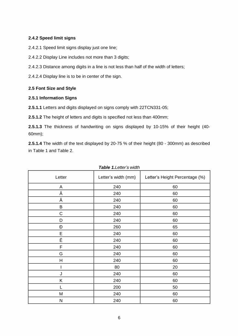
6
2.4.2 Speed limit signs
2.4.2.1 Speed limit signs display just one line;
2.4.2.2 Display Line includes not more than 3 digits;
2.4.2.3 Distance among digits in a line is not less than half of the width of letters;
2.4.2.4 Display line is to be in center of the sign.
2.5 Font Size and Style
2.5.1 Information Signs
2.5.1.1 Letters and digits displayed on signs comply with 22TCN331-05;
2.5.1.2 The height of letters and digits is specified not less than 400mm;
2.5.1.3 The thickness of handwriting on signs displayed by 10-15% of their height (40-
60mm);
2.5.1.4 The width of the text displayed by 20-75 % of their height (80 - 300mm) as described
in Table 1 and Table 2.
Table 1.Letter’s width
Letter Letter’s width (mm) Letter’s Height Percentage (%)
A 240 60
 240 60
Ă 240 60
B 240 60
C 240 60
D 240 60
Đ 260 65
E 240 60
Ê 240 60
F 240 60
G 240 60
H 240 60
I 80 20
J 240 60
K 240 60
L 200 50
M 240 60
N 240 60
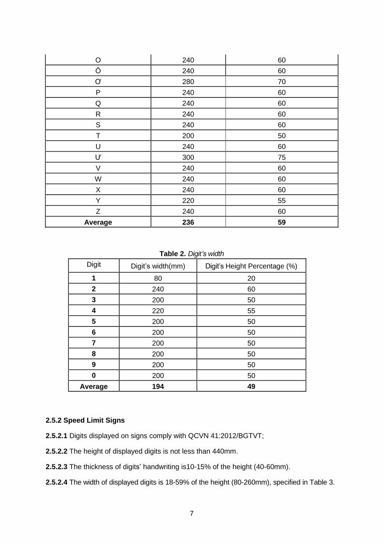
7
O 240 60
Ô 240 60
Ơ 280 70
P 240 60
Q 240 60
R 240 60
S 240 60
T 200 50
U 240 60
Ư 300 75
V 240 60
W 240 60
X 240 60
Y 220 55
Z 240 60
Average 236 59
Table 2. Digit’s width
Digit Digit’s width(mm) Digit’s Height Percentage (%)
1 80 20
2 240 60
3 200 50
4 220 55
5 200 50
6 200 50
7 200 50
8 200 50
9 200 50
0 200 50
Average 194 49
2.5.2 Speed Limit Signs
2.5.2.1 Digits displayed on signs comply with QCVN 41:2012/BGTVT;
2.5.2.2 The height of displayed digits is not less than 440mm.
2.5.2.3 The thickness of digits’ handwriting is10-15% of the height (40-60mm).
2.5.2.4 The width of displayed digits is 18-59% of the height (80-260mm), specified in Table 3.
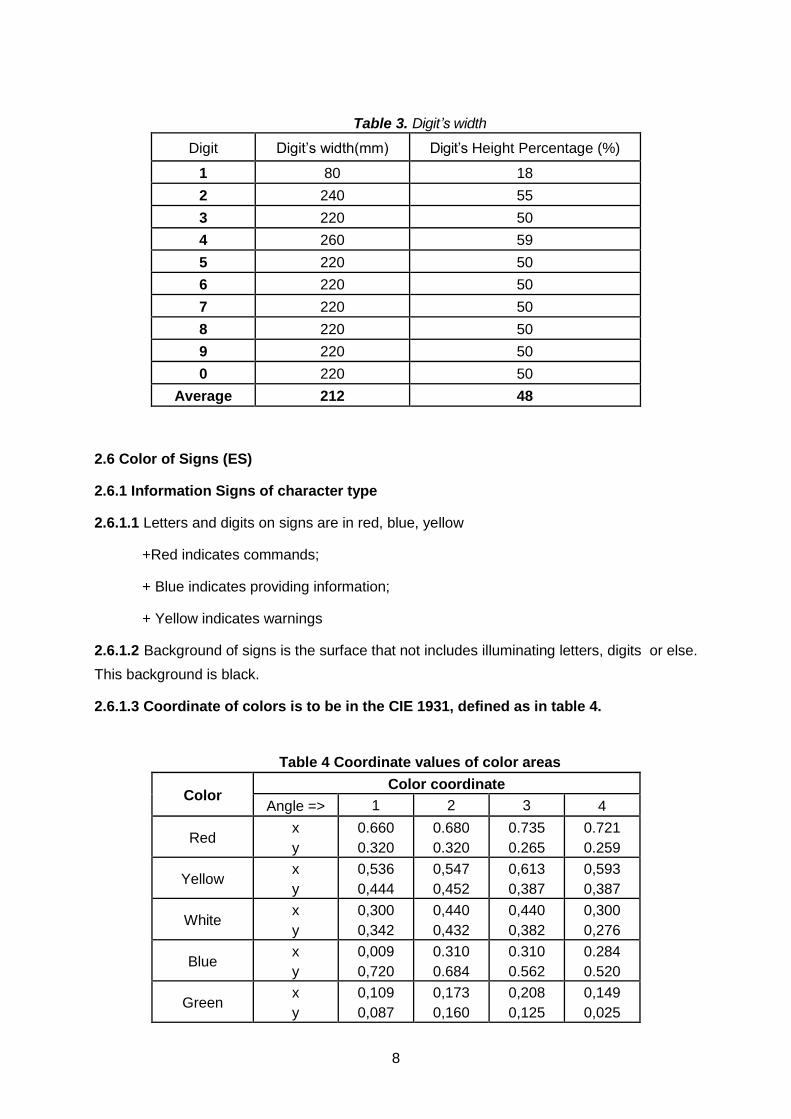
8
Table 3. Digit’s width
Digit Digit’s width(mm) Digit’s Height Percentage (%)
1 80 18
2 240 55
3 220 50
4 260 59
5 220 50
6 220 50
7 220 50
8 220 50
9 220 50
0 220 50
Average 212 48
2.6 Color of Signs (ES)
2.6.1 Information Signs of character type
2.6.1.1 Letters and digits on signs are in red, blue, yellow
+Red indicates commands;
+ Blue indicates providing information;
+ Yellow indicates warnings
2.6.1.2 Background of signs is the surface that not includes illuminating letters, digits or else.
This background is black.
2.6.1.3 Coordinate of colors is to be in the CIE 1931, defined as in table 4.
Table 4 Coordinate values of color areas
Color Color coordinate
Angle => 1 2 3 4
Red x
y
0.660
0.320
0.680
0.320
0.735
0.265
0.721
0.259
Yellow x
y
0,536
0,444
0,547
0,452
0,613
0,387
0,593
0,387
White x
y
0,300
0,342
0,440
0,432
0,440
0,382
0,300
0,276
Blue x
y
0,009
0,720
0.310
0.684
0.310
0.562
0.284
0.520
Green x
y
0,109
0,087
0,173
0,160
0,208
0,125
0,149
0,025
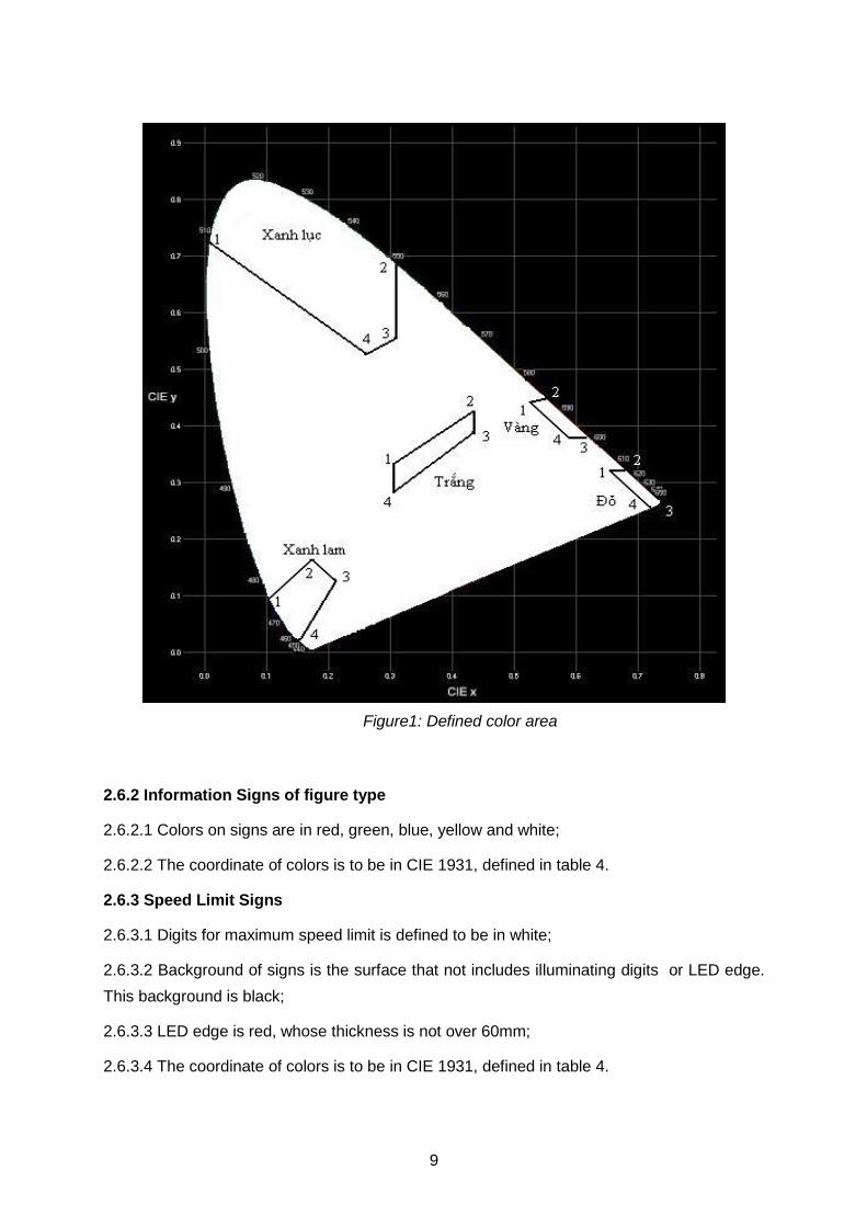
9
Figure1: Defined color area
2.6.2 Information Signs of figure type
2.6.2.1 Colors on signs are in red, green, blue, yellow and white;
2.6.2.2 The coordinate of colors is to be in CIE 1931, defined in table 4.
2.6.3 Speed Limit Signs
2.6.3.1 Digits for maximum speed limit is defined to be in white;
2.6.3.2 Background of signs is the surface that not includes illuminating digits or LED edge.
This background is black;
2.6.3.3 LED edge is red, whose thickness is not over 60mm;
2.6.3.4 The coordinate of colors is to be in CIE 1931, defined in table 4.
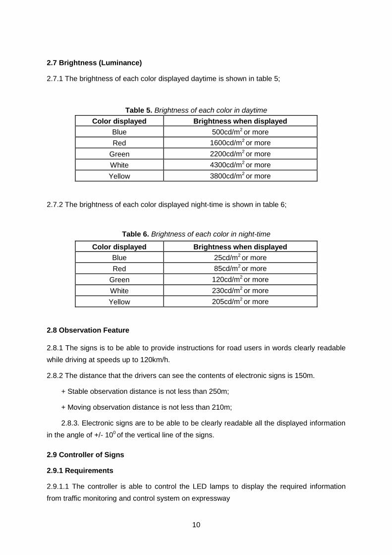
10
2.7 Brightness (Luminance)
2.7.1 The brightness of each color displayed daytime is shown in table 5;
Table 5. Brightness of each color in daytime
Color displayed Brightness when displayed
Blue 500cd/m2 or more
Red 1600cd/m2 or more
Green 2200cd/m2 or more
White 4300cd/m2 or more
Yellow 3800cd/m2 or more
2.7.2 The brightness of each color displayed night-time is shown in table 6;
Table 6. Brightness of each color in night-time
Color displayed Brightness when displayed
Blue 25cd/m2 or more
Red 85cd/m2 or more
Green 120cd/m2 or more
White 230cd/m2 or more
Yellow 205cd/m2 or more
2.8 Observation Feature
2.8.1 The signs is to be able to provide instructions for road users in words clearly readable
while driving at speeds up to 120km/h.
2.8.2 The distance that the drivers can see the contents of electronic signs is 150m.
+ Stable observation distance is not less than 250m;
+ Moving observation distance is not less than 210m;
2.8.3. Electronic signs are to be able to be clearly readable all the displayed information
in the angle of +/- 100 of the vertical line of the signs.
2.9 Controller of Signs
2.9.1 Requirements
2.9.1.1 The controller is able to control the LED lamps to display the required information
from traffic monitoring and control system on expressway
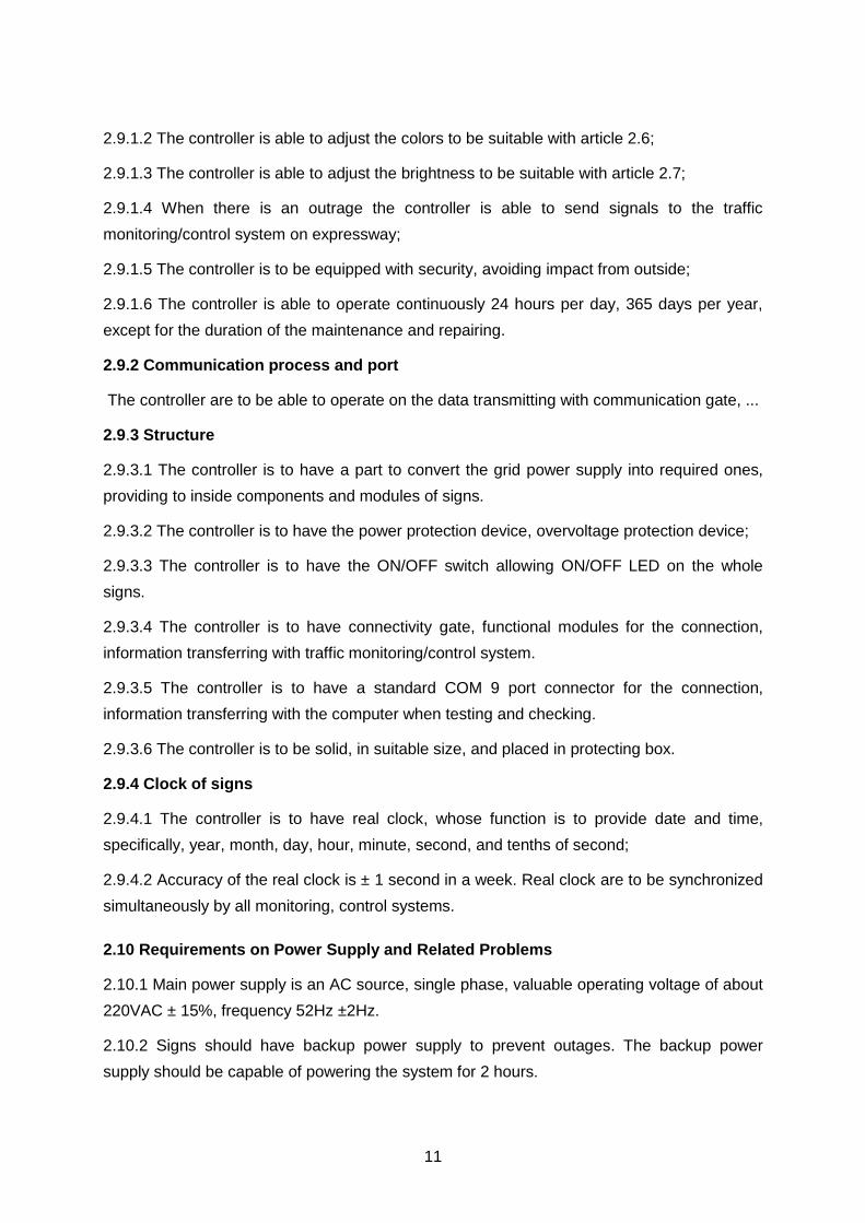
11
2.9.1.2 The controller is able to adjust the colors to be suitable with article 2.6;
2.9.1.3 The controller is able to adjust the brightness to be suitable with article 2.7;
2.9.1.4 When there is an outrage the controller is able to send signals to the traffic
monitoring/control system on expressway;
2.9.1.5 The controller is to be equipped with security, avoiding impact from outside;
2.9.1.6 The controller is able to operate continuously 24 hours per day, 365 days per year,
except for the duration of the maintenance and repairing.
2.9.2 Communication process and port
The controller are to be able to operate on the data transmitting with communication gate, ...
2.9.3 Structure
2.9.3.1 The controller is to have a part to convert the grid power supply into required ones,
providing to inside components and modules of signs.
2.9.3.2 The controller is to have the power protection device, overvoltage protection device;
2.9.3.3 The controller is to have the ON/OFF switch allowing ON/OFF LED on the whole
signs.
2.9.3.4 The controller is to have connectivity gate, functional modules for the connection,
information transferring with traffic monitoring/control system.
2.9.3.5 The controller is to have a standard COM 9 port connector for the connection,
information transferring with the computer when testing and checking.
2.9.3.6 The controller is to be solid, in suitable size, and placed in protecting box.
2.9.4 Clock of signs
2.9.4.1 The controller is to have real clock, whose function is to provide date and time,
specifically, year, month, day, hour, minute, second, and tenths of second;
2.9.4.2 Accuracy of the real clock is ± 1 second in a week. Real clock are to be synchronized
simultaneously by all monitoring, control systems.
2.10 Requirements on Power Supply and Related Problems
2.10.1 Main power supply is an AC source, single phase, valuable operating voltage of about
220VAC ± 15%, frequency 52Hz ±2Hz.
2.10.2 Signs should have backup power supply to prevent outages. The backup power
supply should be capable of powering the system for 2 hours.
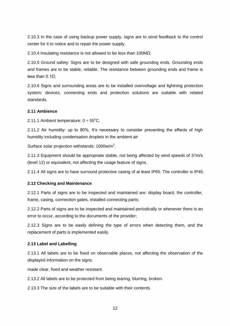
12
2.10.3 In the case of using backup power supply, signs are to send feedback to the control
center for it to notice and to repair the power supply.
2.10.4 Insulating resistance is not allowed to be less than 100MΩ;
2.10.5 Ground safety: Signs are to be designed with safe grounding ends. Grounding ends
and frames are to be stable, reliable. The resistance between grounding ends and frame is
less than 0.1Ω;
2.10.6 Signs and surrounding areas are to be installed overvoltage and lightning protection
system; devices, connecting ends and protection solutions are suitable with related
standards.
2.11 Ambience
2.11.1 Ambient temperature: 0 ÷ 55oC.
2.11.2 Air humidity: up to 80%. It’s necessary to consider preventing the effects of high
humidity including condensation droplets in the ambient air
Surface solar projection withstands: 1000w/m2.
2.11.3 Equipment should be appropriate stable, not being affected by wind speeds of 37m/s
(level 12) or equivalent, not affecting the usage feature of signs.
2.11.4 All signs are to have surround protective casing of at least IP65. The controller is IP45.
2.12 Checking and Maintenance
2.12.1 Parts of signs are to be inspected and maintained are: display board, the controller,
frame, casing, connection gates, installed connecting parts;
2.12.2 Parts of signs are to be inspected and maintained periodically or whenever there is an
error to occur, according to the documents of the provider;
2.12.3 Signs are to be easily defining the type of errors when detecting them, and the
replacement of parts is implemented easily.
2.13 Label and Labelling
2.13.1 All labels are to be fixed on observable places, not affecting the observation of the
displayed information on the signs.
made clear, fixed and weather resistant.
2.13.2 All labels are to be protected from being tearing, blurring, broken.
2.13.3 The size of the labels are to be suitable with their contents.
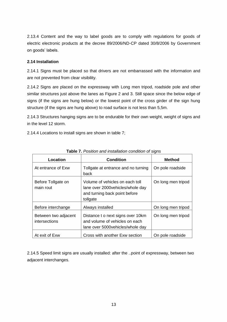
13
2.13.4 Content and the way to label goods are to comply with regulations for goods of
electric electronic products at the decree 89/2006/ND-CP dated 30/8/2006 by Government
on goods’ labels.
2.14 Installation
2.14.1 Signs must be placed so that drivers are not embarrassed with the information and
are not prevented from clear visibility.
2.14.2 Signs are placed on the expressway with Long men tripod, roadside pole and other
similar structures just above the lanes as Figure 2 and 3. Still space since the below edge of
signs (if the signs are hung below) or the lowest point of the cross girder of the sign hung
structure (if the signs are hung above) to road surface is not less than 5,5m.
2.14.3 Structures hanging signs are to be endurable for their own weight, weight of signs and
in the level 12 storm.
2.14.4 Locations to install signs are shown in table 7;
Table 7. Position and installation condition of signs
Location Condition Method
At entrance of Exw Tollgate at entrance and no turning
back
On pole roadside
Before Tollgate on
main rout
Volume of vehicles on each toll
lane over 2000vehicles/whole day
and turning back point before
tollgate
On long men tripod
Before interchange Always installed On long men tripod
Between two adjacent
intersections
Distance t o next signs over 10km
and volume of vehicles on each
lane over 5000vehicles/whole day
On long men tripod
At exit of Exw Cross with another Exw section On pole roadside
2.14.5 Speed limit signs are usually installed: after the ..point of expressway, between two
adjacent interchanges.
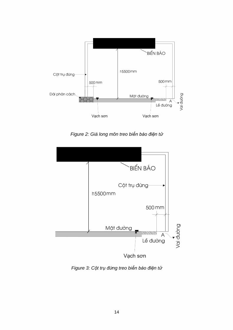
14
Figure 2: Giá long môn treo biển báo điện tử
Figure 3: Cột trụ đứng treo biển báo điện tử
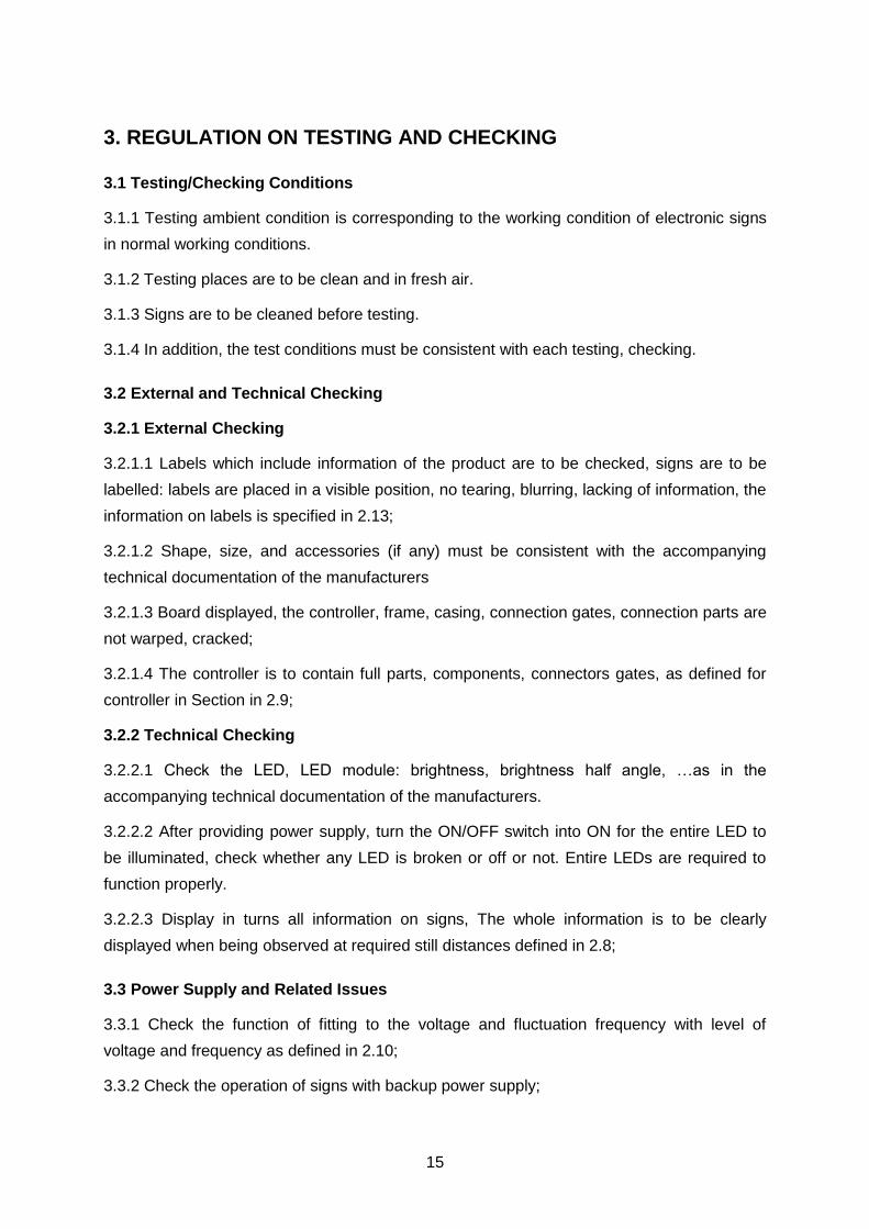
15
3. REGULATION ON TESTING AND CHECKING
3.1 Testing/Checking Conditions
3.1.1 Testing ambient condition is corresponding to the working condition of electronic signs
in normal working conditions.
3.1.2 Testing places are to be clean and in fresh air.
3.1.3 Signs are to be cleaned before testing.
3.1.4 In addition, the test conditions must be consistent with each testing, checking.
3.2 External and Technical Checking
3.2.1 External Checking
3.2.1.1 Labels which include information of the product are to be checked, signs are to be
labelled: labels are placed in a visible position, no tearing, blurring, lacking of information, the
information on labels is specified in 2.13;
3.2.1.2 Shape, size, and accessories (if any) must be consistent with the accompanying
technical documentation of the manufacturers
3.2.1.3 Board displayed, the controller, frame, casing, connection gates, connection parts are
not warped, cracked;
3.2.1.4 The controller is to contain full parts, components, connectors gates, as defined for
controller in Section in 2.9;
3.2.2 Technical Checking
3.2.2.1 Check the LED, LED module: brightness, brightness half angle, …as in the
accompanying technical documentation of the manufacturers.
3.2.2.2 After providing power supply, turn the ON/OFF switch into ON for the entire LED to
be illuminated, check whether any LED is broken or off or not. Entire LEDs are required to
function properly.
3.2.2.3 Display in turns all information on signs, The whole information is to be clearly
displayed when being observed at required still distances defined in 2.8;
3.3 Power Supply and Related Issues
3.3.1 Check the function of fitting to the voltage and fluctuation frequency with level of
voltage and frequency as defined in 2.10;
3.3.2 Check the operation of signs with backup power supply;
16
3.3.3 Check insulating resistance of signs;
3.3.4 Check grounding safety.
3.4 Color Testing and Checking
Measure and check values of colors as defined for each type of signs in conditions,
procedures, equipment to test and check the colors; compare the results with the color
coordinates defined in 2.6 to check whether the colors are in suitable limit or not.
3.5 Information Transmitting Check
3.5.1 Check information transmitting and updating of signs in case of using AC power supply;
3.5.2 Check information transmitting and updating of signs in case of using backup power
supply;
3.5.3 Check information transmitting and updating of signs in case of power failure;
4. REGULATION ON MANAGEMENT
4.1 Management Principles
4.1.1 The expressway sections when coming into operation are to provide fully signs in
accordance with the provisions of this regulation.
4.1.2 On the expressway sections in operation progress, the current signs which are not in
accordance with this regulation is to be gradually adjusted, replaced to avoid waste; the new
added signs must comply with the provisions of this regulation.
4.1.3 When new designing or upgrading expressway, the system of must comply with this
regulation.
4.1.4 It is forbidden to plan trees, build constructions, install equipment causing obscuring,
reducing of recognition distance or fainting of expressway signs.
4.2 Certification and Legal Announcement
4.2.1 All electronic signs manufactured, assembled and traded both domestically and
importedly require the announcement of regulations conformity, in accordance with the
provisions of this regulation. Organization, individual violate the announcement or registration
of regulations conformity, behaviour and degree of the violation will be punished by the law;
4.2.2 Method, order and procedures for announcement of regulations conformity of signs
comply with the "Regulation on Certification of standard conformity, certification of
regulations conformity and announcements of standard conformity, regulations conformity"
17
issued together with circular No. 28/2012/TT-BKHCN dated 12/12/2012 of the Ministry of
Science and Technology and the provisions of law; applicable in detail as follows:
Applying the method 1, (testing of typical samples for the goods) in the Appendix II together
with circular No. 28/2012/TT-BKHCN above. Contents of testing of samples comply with the
provisions of Chapter II of this regulation.
4.2.3 The organization to implement the testing and judgment of the conformation with the
regulation together with circular No. 28/2012/TT-BKHCN is to have the certificate of
registration of business activities as prescribed in Circular No. 08/2009/TT-BKHCN dated
8/4/2009 of Ministry of Science and Technology and Circular No. 10/2011/TT-BKHCN to
change, add some provisions of Circular No. 08/2009/TT-BKHCN dated 30/6/2011 of
Minister of Ministry of Science and Technology and is to be appointed by Ministry of
Transport. The organization to implement the testing and judgment of the conformation with
the regulation is responsible according to Article 20 of Law on quality of products and goods
and other related regulations.
4.3 Responsibility of Road Management Agency
4.3.1 Expressway Management Agency is responsible for executing this regulation, ensuring
the sufficient, consistent and clear sign system on the expressway. In case the signs are lost,
damaged, faint or do not comply with the provisions of the regulation, it’s necessary to
provide additional measures, reparations or replacement to ensure traffic safety.
4.3.2 Officials and employees in charge of road management tasks within their authorities
are to promptly detect any damage, loss and invasive behaviour of sign system, report to the
expressway management agency, or make records or handle those violations of this
regulation by their responsibilities and under the provisions of the law. If not promptly solve,
causing damage to life or serious damage to health and property of others, they must be
punished by the law.
4.4 Responsibility of Road Users
4.4.1 Signs are State’s property. All users of expressway, the participants in traffic and
drivers of all types of vehicles on expressway must protect well the signs on expressway, is
not allowed himself to move, possess, damage or reduce the effect and usefulness of signs
on roads, is responsible for detecting, informing to management agency of expressway the
damage, loss, other problems of the signs on expressway
4.4.2 The person who causes damage or loss of signs on Expressway, are to be responsible
for any loss due to the damage, loss and to pay damages. In case of causing damage, loss
18
without report, once being revealed, the behaviour is regarded as damaging State property
and will be punished by the law.
5. Implementing Organization
5.1 Department of Science and Technology is responsible for management of product quality
and check the regulations conformity announcements of signs in accordance with this
regulation and other current related regulations;
5.2 Department of Science and Technology chairs and coordinates with Directorate of Road
for Vietnam, and related agencies to implement and inspect the implementation of this
regulation;
5.3 During implementation, if there is any difficulties or problems, report to the Ministry of
Transport for consideration and decision to amend accordingly.
添付資料-6
DRAFT QCVN OF
COMMUNICATION SYSTEM FOR EXPRESSWAYS
( SUB-GROUP 6 )
SOCIALIST REPUBLIC OF VIETNAM
QCVN XX: 2014/BGTVT
QUY CHUẨN KỸ THUẬT QUỐC GIA
VỀ HỆ THỐNG THÔNG TIN LIÊN LẠC
TRÊN ĐƯỜNG CAO TỐC
National Technical Regulation on Communication System on
Expressway
HA NOI - 2014
1ST DRAFT
(Sub-Group 6) 2014.02.28
NATIONAL TECHNICAL REGULATION QCVN XX: 2014/BGTVT
1
Foreword
QCVN XX: 2014/BGTVT is compiled by Compiling board of National Regulation on
Expressway Communication System, by Information technology Center, Ministry of
Transport; evaluated by Department of Science and Technology and issued by Minister of
Ministry of Transport in Circular No. xx/2013/TT-BGTVT dated..... 2014.
NATIONAL TECHNICAL REGULATION QCVN XX: 2014/BGTVT
2
NATIONAL TECHNICAL REGULATION ON COMMUNICATION SYSTEM
ON EXPRESSWAY
QUY CHUẨN KỸ THUẬT QUỐC GIA VỀ HỆ THỐNG THÔNG TIN LIÊN LẠC TRÊN ĐƯỜNG CAO TỐC
1 General Regulations .................................................................................................. 4
1.1 Scope ......................................................................................................................... 4
1.2 Application Object ...................................................................................................... 4
1.3 Terminology and Definations ............................................................................ 4
1.4 Abbreviations .................................................................................................... 4
2 Requirements ................................................................................................... 5
3 System Architecture .......................................................................................... 6
4 Switch Equipment Components ........................................................................ 7
4.1 Functions .......................................................................................................... 7
4.2 Structure ........................................................................................................... 7
4.3 Performance ..................................................................................................... 8
4.4 Human-machine Interface ................................................................................. 8
4.5 Communication Interface .................................................................................. 8
4.6 Installation ........................................................................................................ 9
5 Transmission Equipment .................................................................................. 9
5.1 Functions .......................................................................................................... 9
5.2 Structure ......................................................................................................... 10
5.3 Performance ................................................................................................... 10
5.4 Human-machine Interface ............................................................................... 10
5.5 Communication Interface ................................................................................ 10
5.6 Installation ...................................................................................................... 10
6 Fiber Optic Cable ............................................................................................ 11
6.1 Functions ........................................................................................................ 11
6.2 Structure ......................................................................................................... 11
6.3 Performance ................................................................................................... 11
6.4 Human-machine Interface ............................................................................... 12
1ST DRAFT
(Sub-Group 6) 2014.02.28
NATIONAL TECHNICAL REGULATION QCVN XX: 2014/BGTVT
3
6.5 Communication Interface ................................................................................ 12
6.6 Installation ...................................................................................................... 12
7 Network Management System ........................................................................ 13
7.1 General ........................................................................................................... 13
7.2 Functions ........................................................................................................ 13
7.3 Structure ......................................................................................................... 13
7.4 Performance ................................................................................................... 14
7.5 Human-machine Interface ............................................................................... 14
7.6 Communication Interface ................................................................................ 14
7.7 Installation ...................................................................................................... 14
8 Ambient Conditions ......................................................................................... 15
9 Power Supply ................................................................................................. 15
10 Maintenance ................................................................................................... 15
11 Rules on Management .................................................................................... 16
12 Implementation Organization .......................................................................... 16
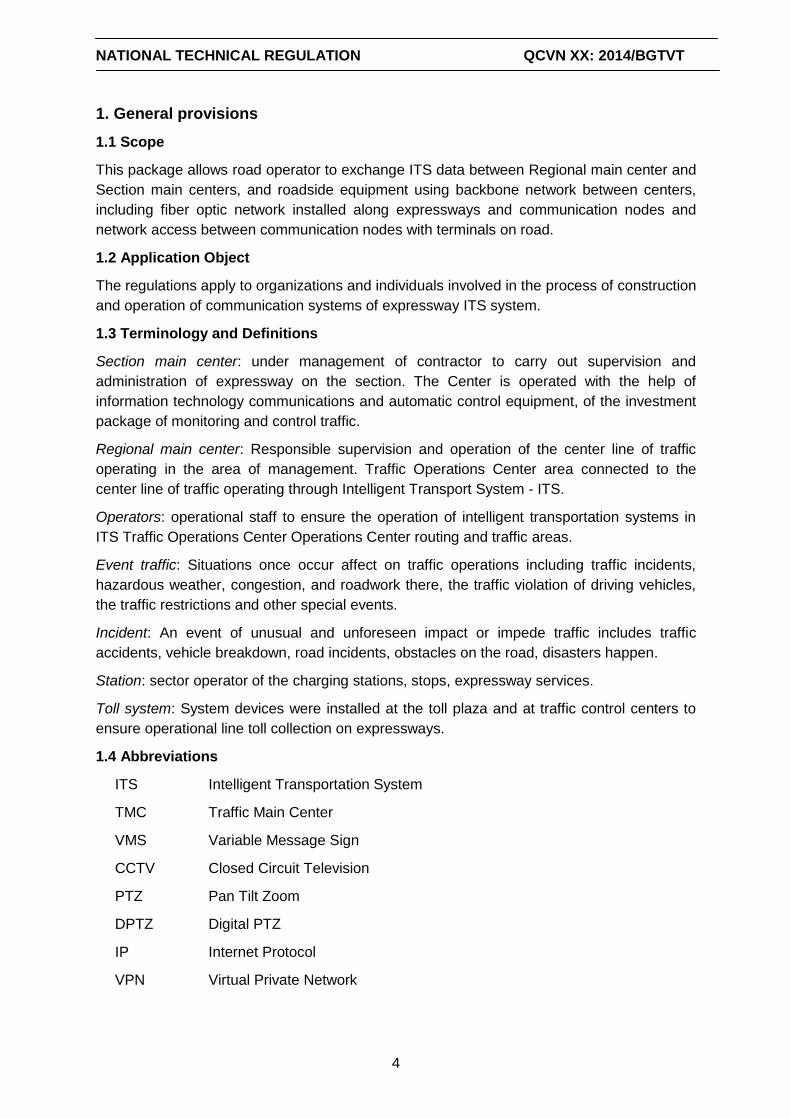
NATIONAL TECHNICAL REGULATION QCVN XX: 2014/BGTVT
4
1. General provisions
1.1 Scope
This package allows road operator to exchange ITS data between Regional main center and
Section main centers, and roadside equipment using backbone network between centers,
including fiber optic network installed along expressways and communication nodes and
network access between communication nodes with terminals on road.
1.2 Application Object
The regulations apply to organizations and individuals involved in the process of construction
and operation of communication systems of expressway ITS system.
1.3 Terminology and Definitions
Section main center: under management of contractor to carry out supervision and
administration of expressway on the section. The Center is operated with the help of
information technology communications and automatic control equipment, of the investment
package of monitoring and control traffic.
Regional main center: Responsible supervision and operation of the center line of traffic
operating in the area of management. Traffic Operations Center area connected to the
center line of traffic operating through Intelligent Transport System - ITS.
Operators: operational staff to ensure the operation of intelligent transportation systems in
ITS Traffic Operations Center Operations Center routing and traffic areas.
Event traffic: Situations once occur affect on traffic operations including traffic incidents,
hazardous weather, congestion, and roadwork there, the traffic violation of driving vehicles,
the traffic restrictions and other special events.
Incident: An event of unusual and unforeseen impact or impede traffic includes traffic
accidents, vehicle breakdown, road incidents, obstacles on the road, disasters happen.
Station: sector operator of the charging stations, stops, expressway services.
Toll system: System devices were installed at the toll plaza and at traffic control centers to
ensure operational line toll collection on expressways.
1.4 Abbreviations
ITS Intelligent Transportation System
TMC Traffic Main Center
VMS Variable Message Sign
CCTV Closed Circuit Television
PTZ Pan Tilt Zoom
DPTZ Digital PTZ
IP Internet Protocol
VPN Virtual Private Network
NATIONAL TECHNICAL REGULATION QCVN XX: 2014/BGTVT
5
2 Requirements
System is capable to exchange data (including video image) among roadside equipment on
expressway, Regional TMC, Section TMC and toll office.
System is capable to transmit conversations among Regional TMC, Section TMC and toll
office.
System is capable to simultaneously transmit instructions to the relevant units with the
highest priority at any time for handling incident, implementing traffic regulations.
The system is capable to determine the location of the incidents on the network
communications and recovery by automatic switching. The system is capable of operating
24 hours a day, 365 days a year thanks to the backup system and required
durability/reliability of equipment.
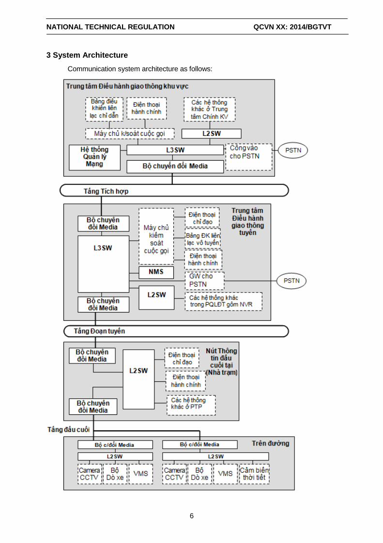
NATIONAL TECHNICAL REGULATION QCVN XX: 2014/BGTVT
6
3 System Architecture
Communication system architecture as follows:
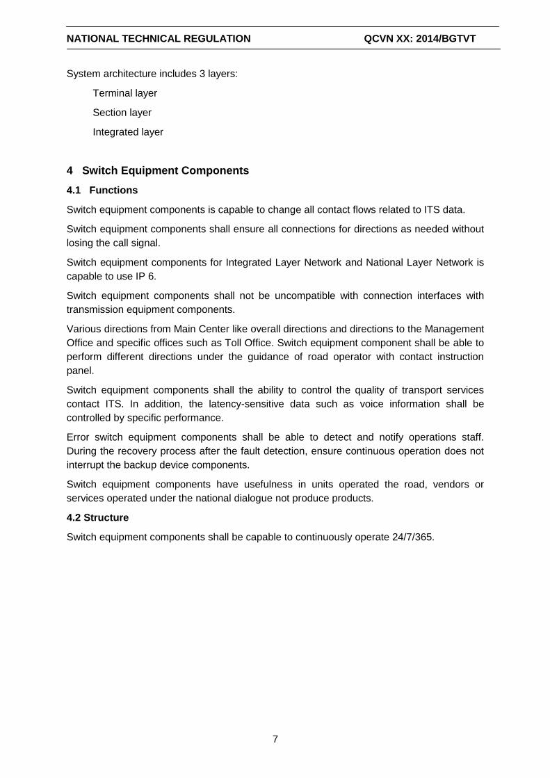
NATIONAL TECHNICAL REGULATION QCVN XX: 2014/BGTVT
7
System architecture includes 3 layers:
Terminal layer
Section layer
Integrated layer
4 Switch Equipment Components
4.1 Functions
Switch equipment components is capable to change all contact flows related to ITS data.
Switch equipment components shall ensure all connections for directions as needed without
losing the call signal.
Switch equipment components for Integrated Layer Network and National Layer Network is
capable to use IP 6.
Switch equipment components shall not be uncompatible with connection interfaces with
transmission equipment components.
Various directions from Main Center like overall directions and directions to the Management
Office and specific offices such as Toll Office. Switch equipment component shall be able to
perform different directions under the guidance of road operator with contact instruction
panel.
Switch equipment components shall the ability to control the quality of transport services
contact ITS. In addition, the latency-sensitive data such as voice information shall be
controlled by specific performance.
Error switch equipment components shall be able to detect and notify operations staff.
During the recovery process after the fault detection, ensure continuous operation does not
interrupt the backup device components.
Switch equipment components have usefulness in units operated the road, vendors or
services operated under the national dialogue not produce products.
4.2 Structure
Switch equipment components shall be capable to continuously operate 24/7/365.
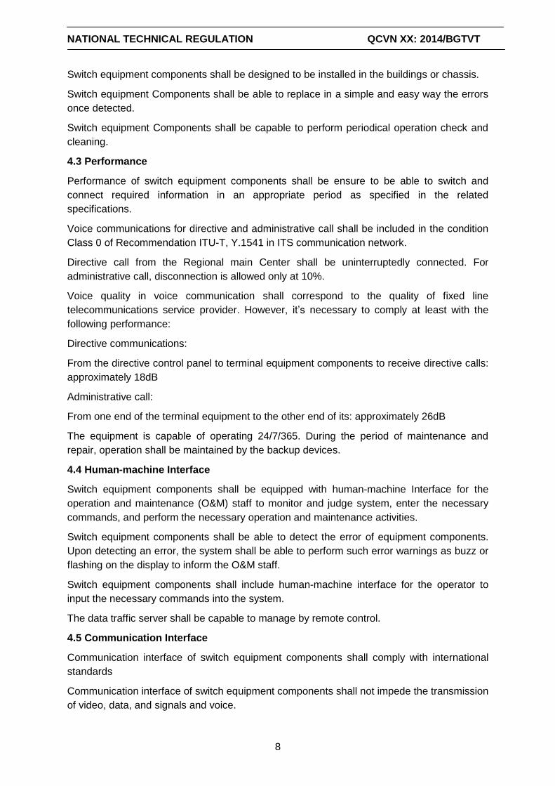
NATIONAL TECHNICAL REGULATION QCVN XX: 2014/BGTVT
8
Switch equipment components shall be designed to be installed in the buildings or chassis.
Switch equipment Components shall be able to replace in a simple and easy way the errors
once detected.
Switch equipment Components shall be capable to perform periodical operation check and
cleaning.
4.3 Performance
Performance of switch equipment components shall be ensure to be able to switch and
connect required information in an appropriate period as specified in the related
specifications.
Voice communications for directive and administrative call shall be included in the condition
Class 0 of Recommendation ITU-T, Y.1541 in ITS communication network.
Directive call from the Regional main Center shall be uninterruptedly connected. For
administrative call, disconnection is allowed only at 10%.
Voice quality in voice communication shall correspond to the quality of fixed line
telecommunications service provider. However, it’s necessary to comply at least with the
following performance:
Directive communications:
From the directive control panel to terminal equipment components to receive directive calls:
approximately 18dB
Administrative call:
From one end of the terminal equipment to the other end of its: approximately 26dB
The equipment is capable of operating 24/7/365. During the period of maintenance and
repair, operation shall be maintained by the backup devices.
4.4 Human-machine Interface
Switch equipment components shall be equipped with human-machine Interface for the
operation and maintenance (O&M) staff to monitor and judge system, enter the necessary
commands, and perform the necessary operation and maintenance activities.
Switch equipment components shall be able to detect the error of equipment components.
Upon detecting an error, the system shall be able to perform such error warnings as buzz or
flashing on the display to inform the O&M staff.
Switch equipment components shall include human-machine interface for the operator to
input the necessary commands into the system.
The data traffic server shall be capable to manage by remote control.
4.5 Communication Interface
Communication interface of switch equipment components shall comply with international
standards
Communication interface of switch equipment components shall not impede the transmission
of video, data, and signals and voice.
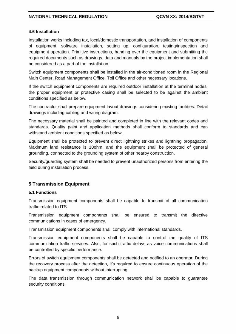
NATIONAL TECHNICAL REGULATION QCVN XX: 2014/BGTVT
9
4.6 Installation
Installation works including tax, local/domestic transportation, and installation of components
of equipment, software installation, setting up, configuration, testing/inspection and
equipment operation. Primitive instructions, handing over the equipment and submitting the
required documents such as drawings, data and manuals by the project implementation shall
be considered as a part of the installation.
Switch equipment components shall be installed in the air-conditioned room in the Regional
Main Center, Road Management Office, Toll Office and other necessary locations.
If the switch equipment components are required outdoor installation at the terminal nodes,
the proper equipment or protective casing shall be selected to be against the ambient
conditions specified as below.
The contractor shall prepare equipment layout drawings considering existing facilities. Detail
drawings including cabling and wiring diagram.
The necessary material shall be painted and completed in line with the relevant codes and
standards. Quality paint and application methods shall conform to standards and can
withstand ambient conditions specified as below.
Equipment shall be protected to prevent direct lightning strikes and lightning propagation.
Maximum land resistance is 10ohm, and the equipment shall be protected of general
grounding, connected to the grounding system of other nearby construction.
Security/guarding system shall be needed to prevent unauthorized persons from entering the
field during installation process.
5 Transmission Equipment
5.1 Functions
Transmission equipment components shall be capable to transmit of all communication
traffic related to ITS.
Transmission equipment components shall be ensured to transmit the directive
communications in cases of emergency.
Transmission equipment components shall comply with international standards.
Transmission equipment components shall be capable to control the quality of ITS
communication traffic services. Also, for such traffic delays as voice communications shall
be controlled by specific performance.
Errors of switch equipment components shall be detected and notified to an operator. During
the recovery process after the detection, it’s required to ensure continuous operation of the
backup equipment components without interrupting.
The data transmission through communication network shall be capable to guarantee
security conditions.
NATIONAL TECHNICAL REGULATION QCVN XX: 2014/BGTVT
10
Switch equipment components shall be useful kinds that road operators or providers of
telecommunications services in other countries verify more than that of original
manufacturing countries.
5.2 Structure
Equipment components shall be capable to continuously operate 24/7/365.
Transmission equipment components shall be designed to be installed in the buildings or
chassis.
Transmission Equipment Components shall be able to replace in a simple and easy way the
errors once detected.
Transmission Equipment Components shall be capable to perform periodical operation
check and cleaning.
5.3 Performance
Performance of the component transmission equipment shall be able to transmit and
connect with required communication traffic in an appropriate period specified in the related
specifications.
Voice communications serving to directive and administrative calls shall be included in the
conditions of the Type 0 of Recommendation ITU-T, Y.1541 in ITS network communications.
Equipment components are to be capable of continuous operation 24/7/365. During
maintenance and repair, equipment is continued to be operated by backup equipment
components.
5.4 Human-machine Interface
Transmission equipment components shall be equipped with human-machine Interface for
the operation and maintenance (O&M) staff to monitor and judge system, enter the
necessary commands, and perform the necessary operation and maintenance activities.
When the transmission equipment components errors are detected by Network Management
system, error alert function by buzz or flashing on the display informs the O&M staff.
Transmission equipment components shall include human-machine interface for the
operator to input the necessary commands into the system.
The data traffic server shall be capable to manage by remote control.
5.5 Communication Interface
Communication interface of switch equipment components shall comply with international
standards.
Communication interface of switch equipment components shall comply with international
standards, and not impede the transmission of data, signals and voice.
5.6 Installation
Installation works including tax, local/domestic transportation, and installation of components
of equipment, software installation, setting up, configuration, testing /inspection and
equipment operation. Primitive instructions, handing over the equipment and submitting the
NATIONAL TECHNICAL REGULATION QCVN XX: 2014/BGTVT
11
required documents such as drawings, data and manuals by the project implementation shall
be considered as part of the installation.
Transmission equipment components shall be installed in the air-conditioned room in the
Regional Main Center, Road Management Office, Toll Office and other necessary locations.
If the transmission equipment components are required outdoor installation at the terminal
nodes, the proper equipment or protective casing shall be selected to be against the ambient
conditions specified as below.
The contractor shall prepare equipment layout drawings considering existing facilities. Detail
drawings including cabling and wiring diagram.
The necessary material shall be painted and completed in line with the relevant codes and
standards. Quality paint and application methods shall conform to standards and can
withstand ambient conditions specified as below.
Equipment shall be protected to prevent direct lightning strikes and propagation. Maximum
land resistance is 10ohm, and the equipment shall be protected of general grounding,
connected to the grounding system of other nearby construction.
Security/guarding system shall be needed to prevent unauthorized persons from entering the
field during installation process.
6 Fiber Optic Cable
6.1 Functions
Optic cable used in ITS communication network shall basically be of transmission distance
far beyond the distance of copper cable.
Single mode optic cable shall be used in the ITS communication network, and it shall comply
with ITU-T G652.D.
Optic cable error shall be detected by the management system and shall be capable to be
detected and notified to the operator. During the recovery process after detection, ensure
continuous operation without interrupting by the backup equipment components.
Data transmitted in the communication network shall be capable to ensure proper operating
conditions.
Optic cable shall be useful kinds that road operators or providers of telecommunications
services in other countries verify more than that of original manufacturing countries.
6.2 Structure
Basically fiber optic cable is inserted in conduit.
Optic cable shall be with sufficient corrosion resistance.
6.3 Performance
Optic cable which is selected shall be capable to transmit required communication specified
requirements in the related specifications.
Performance of optical fiber shall comply with the provisions specified in ITU-T G.652.D.
NATIONAL TECHNICAL REGULATION QCVN XX: 2014/BGTVT
12
The instrumentations to detect the position of optic cable errors, and other equipment for its
operation and maintenance shall be provided by fiber optics cable manufacturers. Also they
offer training how to use the equipment for O&M staffs. However, if it is outsourced to
another unit, the detail requirements shall be specified in contracts.
The necessary equipment used in Fiber Cable replacing and connection equipment or
materials of cable shall be provided by manufacturer to O&M unit for proper installation and
maintenance.
The necessary training shall also be provided to the staffs of O&M units from the
manufacturers, that meets the communications system. However, if it is outsourced to
another unit, the detail requirements shall be specified in contracts.
6.4 Human-machine Interface
When the optic cable errors are detected by Network Management system, error alert
function shall be equipped with whistle or flashing on the display to inform the O&M staff.
The instrumentations used for routine maintenance or optic cable error detection as Optical
Time Domain Reflectometer (OTDR), a suitable size display screen shall be equipped.
6.5 Communication Interface
Optical Fiber Interface communication interface shall comply with international standards,
and not impede the transmission of data, signals and voice.
6.6 Installation
Installation works including tax, local/domestic transportation, and installation of components
of equipment, software installation, setting up, configuration, testing /inspection and
equipment operation. Primitive instructions, handing over the equipment and submitting the
required documents such as drawings, data and manuals by the project implementation shall
be considered as part of the installation.
Optic cable shall be installed in among media switch sets in the Regional Main Center, Road
Management Office, Toll Office and other necessary locations.
If the transmission equipment components are required outdoor installation at the terminal
nodes, the proper equipment or protective casing shall be selected to be against the ambient
conditions specified as below.
The contractor shall prepare equipment layout drawings considering existing facilities. Detail
drawings including cabling and wiring diagram.
The necessary material shall be painted and completed in line with the relevant codes and
standards. Quality paint and application methods shall conform to standards and can
withstand ambient conditions specified as below.
Equipment shall be protected to prevent direct lightning strikes and propagation. Maximum
land resistance is 10ohm, and the equipment shall be protected of general grounding,
connected to the grounding system of other nearby construction.
Security/guarding system shall be needed to prevent unauthorized persons from entering the
field during installation process.
NATIONAL TECHNICAL REGULATION QCVN XX: 2014/BGTVT
13
7 Network Management System
7.1 General
Network Management Systems located in Road Management Office shall be capable to
monitor section and terminal layer under that Road Management Office. NMS system
located in Regional Main Center shall the ability to monitor Integrated Layer Network under
Regional Main Center.
All equipment components shall be monitored by at least one Network Management
Systems mentioned above.
7.2 Functions
Network Management System (NMS) shall be equipped with the following functions;
(1) Function of monitoring, alert and notification
Function of defining the source and recovery many types of alerts and monitoring L3SW,
Switch Layer 2, equipment/ transmission line, roadside equipment. The function of log for
warning is needed, and display and print functions are also required when necessary. Other
necessary function is to notify operating staff by buzz or flashing.
(2) Source Management Function
Function of operation for monitoring condition Layer 3 Switch, Layer 2 Switch, equipment/
transmission line, roadside equipment connected in a required network. When system
configuration is adjusted, functions also required to be equipped include: system
supplementation, equipment component registration and adjust. In the process of replacing
equipment components, it shall have a distinction between "Operating Conditions" and
"being installed".
(3) Performance Monitoring Function
Monitoring function on network communication flow is required.
(4) Check Function
Check function for communication lines and connection of the equipment status shall be
equipped.
(5) Function of switching to the backup equipment components
The function of automatically switching to the backup equipment components shall basically
be equipped to detect the error, and this function can also distinguish operating status of
equipment components like: "Normal" or "abnormal" for both and backup operating
equipment components. Without this function, NMS is required to be equipped to switch
manually or optional.
7.3 Structure
NMS shall be durable enough for continuous operation 24/7/365.
NMS shall be designed to be installed in buildings, office equipment and cabinets.
Structural NMS shall be able to replace a simple and easy way to share error detection.
Structural NMS shall be able to perform inspection activities and periodically cleaned.
NATIONAL TECHNICAL REGULATION QCVN XX: 2014/BGTVT
14
Transmission equipment shall be capable of radiating heat from inside the device.
NMS shall be durable enough for continuously operating 24/7/365.
NMS shall be designed to be installed in the buildings, offices or chassis.
NMS shall be able to be replaced in a simple and easy way the error parts once detected.
NMS shall be capable to perform periodical operation check and cleaning.
Equipment casing shall be capable of heat emission internally.
7.4 Performance
Performance of the NMS shall be ensured for immediately detecting errors, so that NMS
operator can understand the communication network errors before the operator of Traffic
Information/Control detects errors of equipment components, if the errors belong to
communication network.
The goals of NMS monitoring are switches, transmission equipment components,
communication cables, and necessary monitoring content shall be selected to clearly define
error location and status. Equipment components shall be capable of continuous operation
24/7/365.
7.5 Human-machine Interface
NMS shall be equipped with human-machine Interface for the operation and maintenance
(O&M) staff to monitor and judge system, enter the necessary commands, and perform the
necessary operation and maintenance activities.
When errors are detected, NMS shall be capable of error alert by buzz or flashing on the
display to inform the O&M staff.
7.6 Communication Interface
Communication interface NMS shall comply with international standards.
7.7 Installation
Installation works including tax, local/domestic transportation, and installation of components
of equipment, software installation, setting up, configuration, testing /inspection and
equipment operation. Primitive instructions, handing over the equipment and submitting the
required documents such as drawings, data and manuals by the project implementation shall
be considered as part of the installation.
Information of NMS alert installation shall be shared in traffic management room in the
Regional Main Center for the operator of traffic control to detect.
The contractor shall prepare equipment layout drawings, considering existing facilities. Detail
drawings including cabling and wiring diagram.
Software shall be capable of being installed on such operating systems as Microsoft
Windows or Linux or the ones are popular used in many countries.
The necessary material shall be painted and completed in line with the relevant codes and
standards. Quality paint and application methods shall conform to standards and can
withstand ambient conditions specified as below.
NATIONAL TECHNICAL REGULATION QCVN XX: 2014/BGTVT
15
Equipment shall be protected to prevent direct lightning strikes and propagation. Maximum
land resistance is 10ohm, and the equipment shall be protected of general grounding,
connected to the grounding system of other nearby construction.
Security/guarding system shall be needed to prevent unauthorized persons from entering the
field during installation process.
8 Ambient Conditions
Equipment components shall be protected from interference from other electronic devices
and electronic noise on the project site.
Equipment components of transmission, switch and NMS shall be placed in air-conditioned
clean rooms or equivalent frame with IP65 standards to ensure good working condition of
the equipment.
Equipment components shall be installed outdoor with the possibility of performance in
ambient conditions such as natural conditions, meteorological conditions, electronic noise
and other environmental conditions at the project site in Vietnam. The contractor should
inspect the environmental conditions around the project site and has appropriate protection
plans designed for each individual equipment components.
Spare parts of equipment components of switch, transmission and NMS shall be stored in
air-conditioned clean rooms to maintain good performance. Storage room conditions depend
on the requirements for each of equipment in the storage environment.
9 Power Supply
Main power supply is AC 220V, single phase and 50 Hz frequency
Power supply is 220V AC power, phase and frequency of 50 Hz
Power Supply for Information Center/Roadside information system shall be equipped with
backup power supply to ensure the equipment to operate 24/7/365.
10 Maintenance
The system shall be capable to allow check and maintenance in simple and convenient way.
The system shall be capable to easily identify the errors once they are detected, and the
replacement of parts shall be able to be done easily.
Spare parts for the equipment should be provision for a minimum of five (5) years since the
equipment has been handed over to the road management agency, and manufacturers shall
ensure the supply of spare equipment during this period.
Manufacturers of transmission equipment and fiber optic cable shall be required to submit
the necessary documents relating to operation and maintenance, such as manuals and test
equipment list, also provide necessary training for O&M personnel of related equipment.
NATIONAL TECHNICAL REGULATION QCVN XX: 2014/BGTVT
16
Manufacturers of transmission equipment and fiber optic shall be required to sign a contract
with the road management agency on technical support services for operation and
maintenance related to the supplied equipment, and provides necessary services under this
contract contents.
11 Rules of Management
The system of traffic monitoring camera is an essential component to be prepared to invest
in the project on ITS construction on expressways.
The operation and maintenance of expressway monitoring camera shall be done according
to the Ministry of Transportation or investor approval on the basis of compliance:
- Regulation of the Government on management, exploitation and maintenance of
expressways;
- Plans on expressways traffic is approved by authorized level;
- The coordination scheme among operating units on expressways;
The contractor assigned to manage expressway maintenance work performed operation and
maintenance of traffic monitoring camera by taking funding from sources online
management costs according to the Ministry of Transportation approval.
12 Implementation Organization
The organizations and individuals involved in the planning for development, construction
investment, management, operation and maintenance of expressway monitoring camera
system shall comply with the technical standards specified in this regulation and other
relevant legal documents.
In case of technical regulations, standards, technical documents cited in this technical
regulation have got change; supplement or replacement, it’s to comply with the provisions in
the new documents.
Directorate for Road of Vietnam (DRVN) is responsible for:
- Develop rules on coordination, operation of the intelligent traffic system - ITS including
traffic monitoring camera system in operation management, exploitation and maintenance of
expressways.
- Check and supervise the construction process and put into use monitoring camera systems
strictly according to regulations issued.
DRVN shall preside and coordinate with the Department of Science and Technology
(Ministry of Transport) and authorities to deploy guide and organize the implementation of
this Technical Regulation./.

添付資料-7
DRAFT QCVN OF
ETC SYSTEM FOR EXPRESSWAYS ( SUB-GROUP 7 )
SOCIALIST REPUBLIC OF VIETNAM
QCVN xx: 2014/BGTVT
QUY CHUẨN KỸ THUẬT QUỐC GIA VỀ THU PHÍ ĐIỆN TỬ TRÊN ĐƯỜNG CAO TỐC National Technical Regulation on Electronic Toll Collection (ETC)
for Expressway
HANOI - 2014
1ST DRAFT
(Sub-Group 7) 2014.03.30
QCVN xx:2014/BGTVT
Page 2
TABLE CONTENT
Page
PREFACE
1. GENERAL REGULATION
1.1 Scope ................................................................................................................ 5
1.2 Application Object .............................................................................................. 5
1.3 Reference Materials ........................................................................................... 5
1.4 Terms and Definitions ........................................................................................ 6
1.5 Abbreviations ..................................................................................................... 7
2. REGULATIONS ON TOLL COUNTING ............................................................. 9
2.1 Defining Type of Vehicle .................................................................................... 9
2.2 Defining Mileage of Vehicle ............................................................................... 9
3. TOLL COLLECTION PROCEDURE ................................................................ 12
3.1 General Procedure .......................................................................................... 12
3.2 OBU Issuance .................................................................................................. 13
3.3 Account Refilling .............................................................................................. 13
3.4 Tollgate Processing ......................................................................................... 13
3.5 Bank Settlement System Processing ............................................................... 18
4. TECHNICAL REQUIREMENTS ....................................................................... 19
4.1 General Requirements ..................................................................................... 19
4.2 Tollgate Structure ............................................................................................ 19
4.3 System Equipment ........................................................................................... 22
4.4 System Software .............................................................................................. 28
4.5 Transaction of Information ............................................................................... 31
4.6 Model of Connection and Settlement among Tollgates and Bank ................... 36
5. REGULATIONS ON REPORTS ...................................................................... 39
QCVN xx:2014/BGTVT
Page 3
6. REGULATIONS ON MANAGEMENT .............................................................. 39
7. IMPLEMENTATION ......................................................................................... 40
APPENDIX 1: Samples of arranging equipment on Touch & Go lane ........................ 40
APPENDIX 2: Samples of arranging equipment on ETC lane .................................... 42
APPENDIX 3: Samples of arranging equipment on combination of Touch & Go and ETC lanes ..... 43
APPENDIX 4: Operation steps at ETC lane ............................................................... 44
APPENDIX 5: Basic Specifications of main equipment .............................................. 50
APPENDIX 6: Samples of standard reports ............................................................... 52
QCVN xx:2014/BGTVT
Page 4
FOREWORD
QCVN XX: 2013/BGTVT – National technical regulation on Electronic Toll
Collection (ETC) for Expressway is compiled by Compiling committee of National
technical regulations for electronic toll collection for expressway (established
under Decision No. 2250/QD-BGTVT dated 31/07/2013 of Ministry of Transport),
evaluated by Ministry of Science and Technology and issued by Ministry of Transport in
line with Circular No. xx/2014/TT-BGTVT dated..... 2014 of Ministry of Transport.
QCVN xx:2014/BGTVT
Page 5
NATIONAL TECHNICAL REGULATION QCVNXX: 2014/BGTVT
Quy chuẩn kỹ thuật Quốc gia về thu phí điện tử trên đường cao tốc
National Technical Regulation on Electronic Toll Collection System (ETC) for
Expressway
1. GENERAL PROVISIONS
1.1 Scope
- This national regulationation regulates basic requirements on ETC system
installed at tollgates collecting toll of using expressways, including parts of
system installed in centers/office of managing toll collection.
1.2 Application Object
- This national regulationation applies for organizations and individuals related in
investment construction, operation, management and manatenance of
Electronic toll collection on expressway.
1.3 Reference Materials
Draft ITS design standard (Revised version). Japan International
Cooperation Agency (JICA), April 2013.
QCVN 41:2012/BGTVT. National Technical Regulation on road signs
and signals.
Circular No. 159/2013/TT-BTC dated 14/11/2013 of the Ministry of Finance
guiding the regime of collection, payment, management and road usage toll
for ROI (Return On Investment) of road construction.
TCVN 4054-05. Highway - Design requirements.
CEN/TC278/5.8GHz DSRC: European standards for dedicated short range
communications (DSRC) band 5.8GHz passive.
ARIB STD-T75: Japanese Standard for dedicated short range
communications (DSRC) band 5.8GHz active.
QCVN xx:2014/BGTVT
Page 6
ISO/IEC 18000-6C: American Standard RFID frequency range of 860 MHz
to 960 MHz.
1.4 Terms and Definitions
In this regulation, terms and definitions are explained as follows:
“Electronic Toll Collection (ETC) on expressway”: is understood as a closed
method, including touch & go lanes and ETC lanes, moreover, it can be
combined touch & go and ETC on one lane.
“Toll collection method”: is the method to collect toll on lanes, in this
regulation, there are two types of toll collection: T&G and ETC.
“Close toll collection”: is the method to collect toll that vehicle (car) is to pay
a toll rate in line with its type and mileage on toll road section.
“Toll procedure” is an obligated procedure to follow when road toll is
collected.
“Entry lanes”: Are the lanes at tollgate where vehicles enter expressway, for
defining the entering point of vehicles.
“Exit lanes” is the lanes at tollgate where vehicles leave expressway, for
defining the exit point of vehicles, defining their mileage, based on that due
toll is counted.
“ETC toll collection”: is the method of automatic toll collection allowing
vehicles passing through tollgate to pay toll without stopping, combined
using of IC card and OBU (if they are separated) or only OBU (IC card is
integrated in OBU).
“Touch & Go toll collection” is the method of toll collection that drivers are to
stop when passing through tollgate, using prepaid IC card to touch or insert
in reading area of card reader installed at entry and exit lanes for executing
toll payment.
“IC card”: is an electronic card for reading/writing and storing of vehicle
owner’s account information date, serving for toll rate counting at ETC lane.
“On Board Unit”: is an electronic equipment placed on vehicle to
communicate with roadside equipment, also called toll collection equipment
on vehicle, serving for toll rate counting at ETC lane.
QCVN xx:2014/BGTVT
Page 7
“Exit toll rate receipt”: is a receipt for exit gates, printed following sample as
soon as Ministry of Finance and Tax Bureau have approved, providing for
drivers after their toll payment at the exit for (manual lane), as valued as an
receipt.
“Special card”: is the type of card for opening barrier, letting vehicle to pass
through in special cases under tollgate regulations.
“Toll collector”: is tollgate’s staff, in the duty of colleting toll, working in cabin
or commuter ticket selling place.
“Monitoring person” is tollgate’s staff, in the duty of monitoring toll collection
process, work process in monitoring office
“Technical person”: the staff of tollgate, who has sufficient technical major
ability, understands toll collection equipment system in tollgate, is assigned
to maintain, repair this system under tollgate regulations.
“Bank settlement system”: is a system for road usage toll payment through
customer’s account in settlement units (settlement units are able to be bank
or other organization having settlement function).
“Control center for banking” is the center of management and transaction of
toll collection processing as well as related operations (control, settlement of
toll revenue ...) among banks and toll collection units, and among banks.
“Section road management center”: is an agency to manage and control
traffic of an expressway, road section.
“Regional road management center”: is an agency to manage and control
traffic of expressway, road sections in a specific region.
“Transceiver”: is the short signal receiver and transmitter to exchange message
for ETC toll collection between equipment of section management unit (road
operator) and OBU on customer vehicle using nonstop toll collection services.
1.5 Abbreviations
QCVN: National regulation.
TCVN: National Standard.
MOT: Ministry of Transport.
QCVN xx:2014/BGTVT
Page 8
ISO: International Organization for Standardization (An organization for
setting up International Standards, with many representatives from many
National Standards Bodies).
ITS: Intelligent Transport Systems (support human and good transportation
with information and communication technology for using traffic
infrastructure and traffic means safely and effectively).
DSRC: Dedicated Short Range Communications (allow high speed
communication between vehicle and roadside, or among lanes, in this
document it is for ITS).
ETC: Electronic Toll Collection (is an electronic toll collection method,
excluding cash, travel card or credit card are used at cabins).
OBU: On Board Unit (equipment placed on vehicle to communicate with
road side equipment, so called as toll collection equipment on vehicle).
ALPR: Automatic License Plate Recognition.
IC: Integrated Circuit
ID: Identifier.
RFID (Radio-frequency identification).
T&G: Touch & Go
CPU: central processing unit.
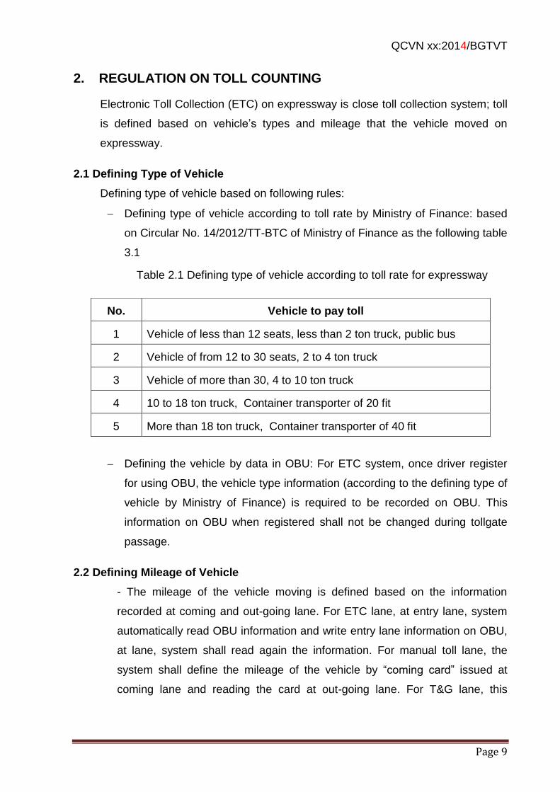
QCVN xx:2014/BGTVT
Page 9
2. REGULATION ON TOLL COUNTING
Electronic Toll Collection (ETC) on expressway is close toll collection system; toll
is defined based on vehicle’s types and mileage that the vehicle moved on
expressway.
2.1 Defining Type of Vehicle
Defining type of vehicle based on following rules:
Defining type of vehicle according to toll rate by Ministry of Finance: based
on Circular No. 14/2012/TT-BTC of Ministry of Finance as the following table
3.1
Table 2.1 Defining type of vehicle according to toll rate for expressway
Defining the vehicle by data in OBU: For ETC system, once driver register
for using OBU, the vehicle type information (according to the defining type of
vehicle by Ministry of Finance) is required to be recorded on OBU. This
information on OBU when registered shall not be changed during tollgate
passage.
2.2 Defining Mileage of Vehicle
- The mileage of the vehicle moving is defined based on the information
recorded at coming and out-going lane. For ETC lane, at entry lane, system
automatically read OBU information and write entry lane information on OBU,
at lane, system shall read again the information. For manual toll lane, the
system shall define the mileage of the vehicle by “coming card” issued at
coming lane and reading the card at out-going lane. For T&G lane, this
No. Vehicle to pay toll
1 Vehicle of less than 12 seats, less than 2 ton truck, public bus
2 Vehicle of from 12 to 30 seats, 2 to 4 ton truck
3 Vehicle of more than 30, 4 to 10 ton truck
4 10 to 18 ton truck, Container transporter of 20 fit
5 More than 18 ton truck, Container transporter of 40 fit
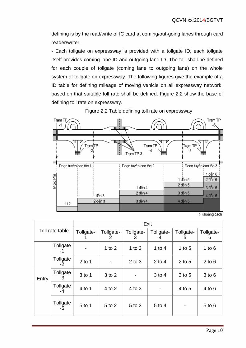
QCVN xx:2014/BGTVT
Page 10
defining is by the read/write of IC card at coming/out-going lanes through card
reader/writer.
- Each tollgate on expressway is provided with a tollgate ID, each tollgate
itself provides coming lane ID and outgoing lane ID. The toll shall be defined
for each couple of tollgate (coming lane to outgoing lane) on the whole
system of tollgate on expressway. The following figures give the example of a
ID table for defining mileage of moving vehicle on all expressway network,
based on that suitable toll rate shall be defined. Figure 2.2 show the base of
defining toll rate on expressway.
Figure 2.2 Table defining toll rate on expressway
Toll rate table
Exit
Tollgate-1
Tollgate-2
Tollgate-3
Tollgate-4
Tollgate-5
Tollgate-6
Entry
Tollgate-1
- 1 to 2 1 to 3 1 to 4 1 to 5 1 to 6
Tollgate-2
2 to 1 - 2 to 3 2 to 4 2 to 5 2 to 6
Tollgate-3
3 to 1 3 to 2 - 3 to 4 3 to 5 3 to 6
Tollgate-4
4 to 1 4 to 2 4 to 3 - 4 to 5 4 to 6
Tollgate-5
5 to 1 5 to 2 5 to 3 5 to 4 - 5 to 6
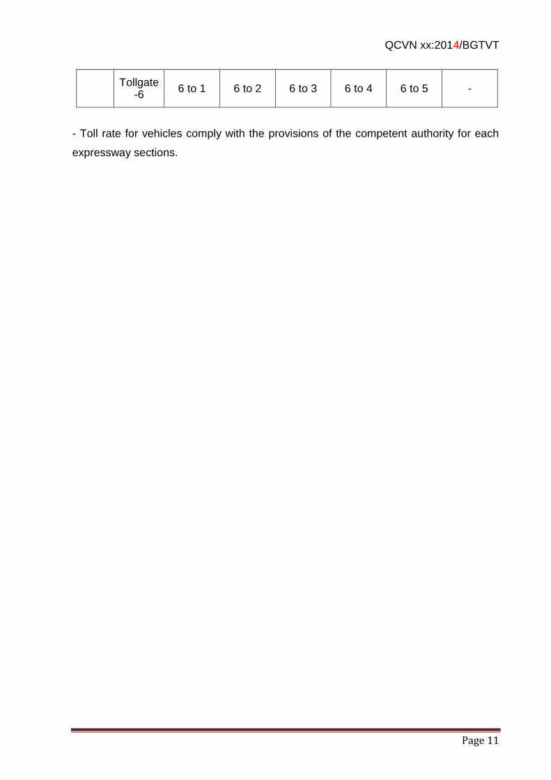
QCVN xx:2014/BGTVT
Page 11
Tollgate-6
6 to 1 6 to 2 6 to 3 6 to 4 6 to 5 -
- Toll rate for vehicles comply with the provisions of the competent authority for each
expressway sections.
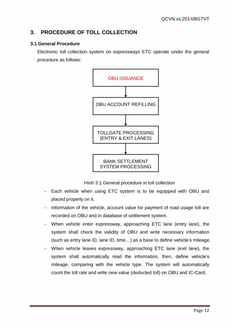
QCVN xx:2014/BGTVT
Page 12
3. PROCEDURE OF TOLL COLLECTION
3.1 General Procedure
Electronic toll collection system on expressways ETC operate under the general
procedure as follows:
Hình 3.1 General procedure in toll collection
Each vehicle when using ETC system is to be equipped with OBU and
placed properly on it.
Information of the vehicle, account value for payment of road usage toll are
recorded on OBU and in database of settlement system.
When vehicle enter expressway, approaching ETC lane (entry lane), the
system shall check the validity of OBU and write necessary information
(such as entry lane ID, lane ID, time…) as a base to define vehicle’s mileage.
When vehicle leaves expressway, approaching ETC lane (exit lane), the
system shall automatically read the information, then, define vehicle’s
mileage, comparing with the vehicle type. The system will automatically
count the toll rate and write new value (deducted toll) on OBU and IC-Card.
OBU ISSUANCE
OBU ACCOUNT REFILLING
TOLLGATE PROCESSING (ENTRY & EXIT LANES)
BANK SETTLEMENT SYSTEM PROCESSING
QCVN xx:2014/BGTVT
Page 13
Transactions are processed and saved as database of tollgate, later on, it is
transmitted to bank settlement to compare and check to ensure proper and
sufficient toll collection for each vehicle passing tollgate.
The comparing, settlement, and balancing for related units are processed by
bank settlement system based on transaction reports at tollgates.
3.2 OBU Issuance
The issuing of OBU using for ETC lane can be done by toll collection
management unit, or through bank (bank branches or other channels of
bank).
When issuing and distribution of OBU to driver, his/her information and
his/her vehicle’s information shall be collected based on the vehicle
registration files and recorded on OBU, in database of tollgate and of the
bank settlement.
Information to be recorded on OBU: regulations on OBU data sets and data
components in 4.5.2
3.3 Account Refilling
When using OBU, the vehicle owner can get an account with the information
to be recorded in IC card or OBU using for paying for road usage toll.
Vehicle owner are to refill the account, the value of refilled money is
recorded in the account to pay toll automatically when the driver pass
through tollgates.
Moreover, customer can use an account opened at bank (personal account,
ATM account…) to refill into the account for paying road usage toll or update
the time to use the account after that, in equivalent with the refilled amount.
Accounts using for paying for the vehicle owner’s road usage toll is to be
updated on OBU/IC-Card when the vehicle moving through automatic ETC
toll lanes. After refilling (into personal account, ATM account...) for next
times the value shall automatically be recorded on the account when OBU
vehicle pass through tollgates.
3.4 Toll Processing
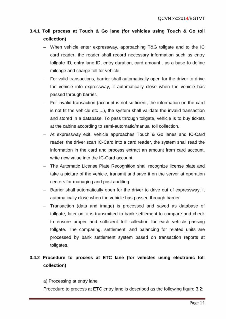
QCVN xx:2014/BGTVT
Page 14
3.4.1 Toll process at Touch & Go lane (for vehicles using Touch & Go toll
collection)
When vehicle enter expressway, approaching T&G tollgate and to the IC
card reader, the reader shall record necessary information such as entry
tollgate ID, entry lane ID, entry duration, card amount…as a base to define
mileage and charge toll for vehicle.
For valid transactions, barrier shall automatically open for the driver to drive
the vehicle into expressway, it automatically close when the vehicle has
passed through barrier.
For invalid transaction (account is not sufficient, the information on the card
is not fit the vehicle etc ...), the system shall validate the invalid transaction
and stored in a database. To pass through tollgate, vehicle is to buy tickets
at the cabins according to semi-automatic/manual toll collection.
At expressway exit, vehicle approaches Touch & Go lanes and IC-Card
reader, the driver scan IC-Card into a card reader, the system shall read the
information in the card and process extract an amount from card account,
write new value into the IC-Card account.
The Automatic License Plate Recognition shall recognize license plate and
take a picture of the vehicle, transmit and save it on the server at operation
centers for managing and post auditing.
Barrier shall automatically open for the driver to drive out of expressway, it
automatically close when the vehicle has passed through barrier.
Transaction (data and image) is processed and saved as database of
tollgate, later on, it is transmitted to bank settlement to compare and check
to ensure proper and sufficient toll collection for each vehicle passing
tollgate. The comparing, settlement, and balancing for related units are
processed by bank settlement system based on transaction reports at
tollgates.
3.4.2 Procedure to process at ETC lane (for vehicles using electronic toll
collection)
a) Processing at entry lane
Procedure to process at ETC entry lane is described as the following figure 3.2:
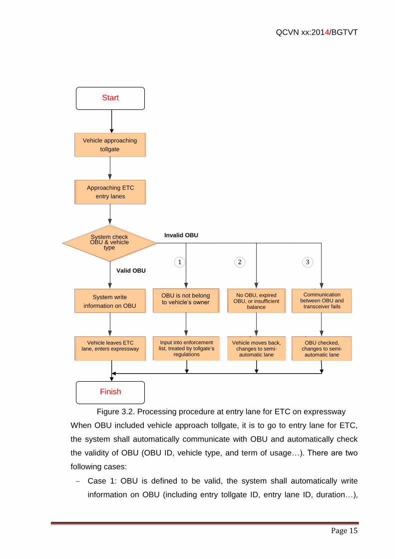
QCVN xx:2014/BGTVT
Page 15
Phương tiện tới trạm thu phí
Đi tới các làn vào ETC
Hệ thống kiểm tra OBU và loại xe
Hệ thống ghi thông tin lên OBU
OBU hợp lệ
OBU không hợp lệ
Phương tiện rời khỏi làn ETC vào cao tốc
Xe có OBU nhưng không phải OBU của
chủ xe
Không có OBU,
OBU hết hạn hoặc không đủ tiền
Vào danh sách cưỡng
chế và xử lý theo quy định của trạm
Tài xế lùi xe lại,
chuyển qua làn bán
tự động
11 22
Giao tiếp giữa OBU
và transceiver không
thành công
Kiểm tra OBU, và
chuyển qua làn bán tự động
33
Figure 3.2. Processing procedure at entry lane for ETC on expressway
When OBU included vehicle approach tollgate, it is to go to entry lane for ETC,
the system shall automatically communicate with OBU and automatically check
the validity of OBU (OBU ID, vehicle type, and term of usage…). There are two
following cases:
Case 1: OBU is defined to be valid, the system shall automatically write
information on OBU (including entry tollgate ID, entry lane ID, duration…),
Vehicle approaching
tollgate
Approaching ETC
entry lanes
System write
information on OBU
OBU is not belong to vehicle’s owner
No OBU, expired OBU, or insufficient
balance
Communication between OBU and
transceiver fails
Vehicle leaves ETC lane, enters expressway
Input into enforcement list, treated by tollgate’s
regulations
OBU checked, changes to semi-automatic lane
Vehicle moves back, changes to semi-automatic lane
Invalid OBU
Valid OBU
System check OBU & vehicle
type
Start
Finish
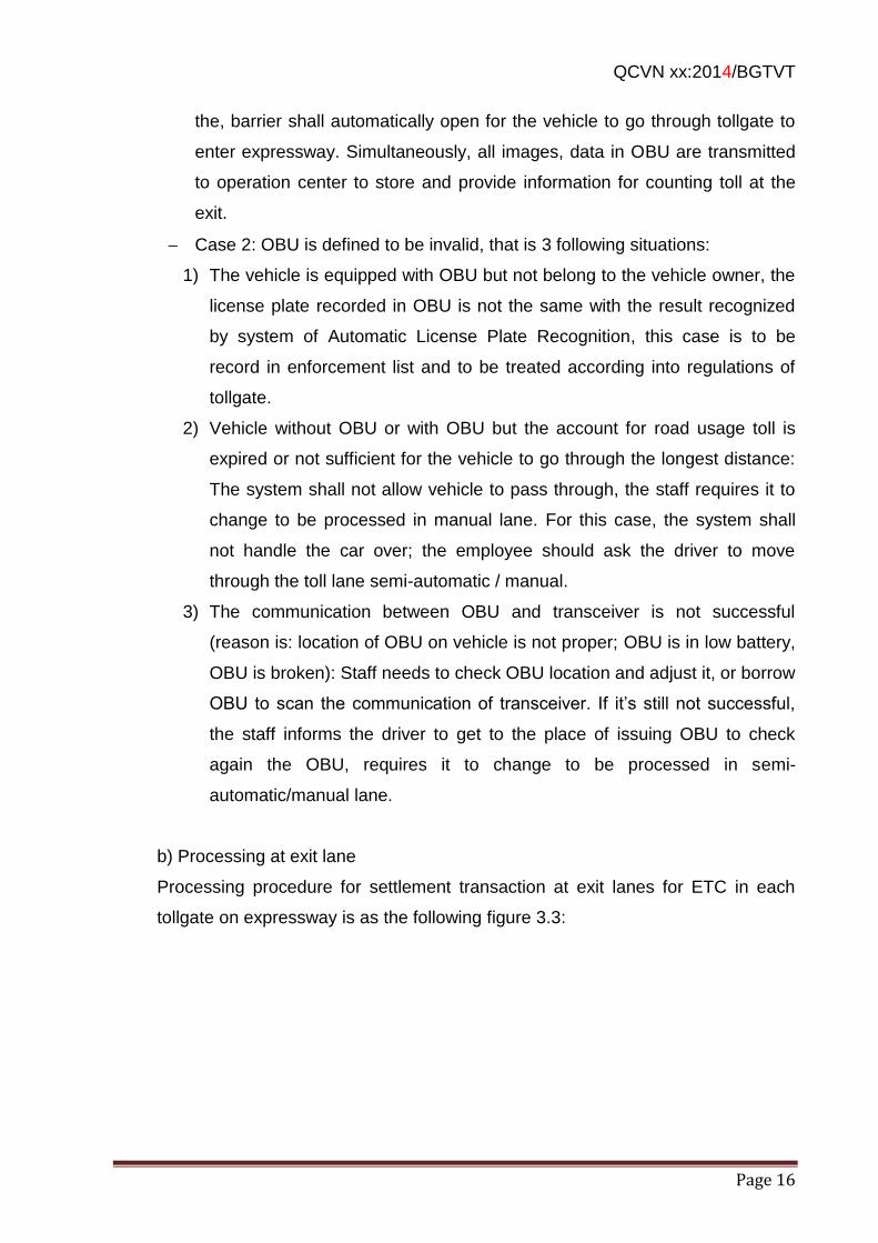
QCVN xx:2014/BGTVT
Page 16
the, barrier shall automatically open for the vehicle to go through tollgate to
enter expressway. Simultaneously, all images, data in OBU are transmitted
to operation center to store and provide information for counting toll at the
exit.
Case 2: OBU is defined to be invalid, that is 3 following situations:
1) The vehicle is equipped with OBU but not belong to the vehicle owner, the
license plate recorded in OBU is not the same with the result recognized
by system of Automatic License Plate Recognition, this case is to be
record in enforcement list and to be treated according into regulations of
tollgate.
2) Vehicle without OBU or with OBU but the account for road usage toll is
expired or not sufficient for the vehicle to go through the longest distance:
The system shall not allow vehicle to pass through, the staff requires it to
change to be processed in manual lane. For this case, the system shall
not handle the car over; the employee should ask the driver to move
through the toll lane semi-automatic / manual.
3) The communication between OBU and transceiver is not successful
(reason is: location of OBU on vehicle is not proper; OBU is in low battery,
OBU is broken): Staff needs to check OBU location and adjust it, or borrow
OBU to scan the communication of transceiver. If it’s still not successful,
the staff informs the driver to get to the place of issuing OBU to check
again the OBU, requires it to change to be processed in semi-
automatic/manual lane.
b) Processing at exit lane
Processing procedure for settlement transaction at exit lanes for ETC in each
tollgate on expressway is as the following figure 3.3:
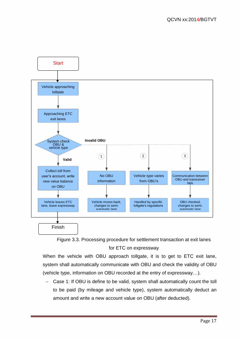
QCVN xx:2014/BGTVT
Page 17
Figure 3.3. Processing procedure for settlement transaction at exit lanes
for ETC on expressway
When the vehicle with OBU approach tollgate, it is to get to ETC exit lane,
system shall automatically communicate with OBU and check the validity of OBU
(vehicle type, information on OBU recorded at the entry of expressway…).
Case 1: If OBU is define to be valid, system shall automatically count the toll
to be paid (by mileage and vehicle type), system automatically deduct an
amount and write a new account value on OBU (after deducted).
Phương tiện tới trạm thu phí
Đi tới các làn ra ETC
Hệ thống kiểm tra OBU và loại xe
Thực hiện thu phí trên tài khoản của khách
hàng, đồng thời ghi giá trị tài khoản mới lên
OBU
Hợp lệ
Không hợp lệ
Phương tiện rời khỏi làn ETC & ra khỏi cao
tốc
OBU không có thông
tin ghi nhận tại làn vào
Loại xe không khớp với loại xe trong OBU
Lái xe lùi lại và chuyển qua làn Bán tự
động
Xử lý theo quy định cụ thể của trạm
11 22
Giao tiếp giữa OBU và transceiver không
thành công
Kiểm tra OBU, và chuyển qua làn bán tự
động
33
Vehicle approaching
tollgate
Approaching ETC
exit lanes
Collect toll from
user’s account, write
new value balance
on OBU
No OBU
information
recorded in entry
lane
Vehicle type varies
from OBU’s
Communication between OBU and transceiver
fails
Vehicle moves back, changes to semi-automatic lane
Handled by specific tollgate’s regulations
OBU checked, changes to semi-automatic lane
Vehicle leaves ETC lane, leave expressway
Invalid OBU
Valid
System check OBU &
vehicle type
Finish
Start
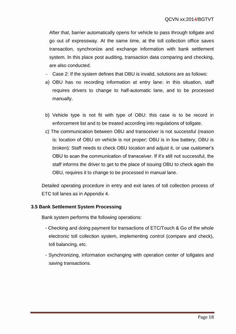
QCVN xx:2014/BGTVT
Page 18
After that, barrier automatically opens for vehicle to pass through tollgate and
go out of expressway. At the same time, at the toll collection office saves
transaction, synchronize and exchange information with bank settlement
system. In this place post auditing, transaction data comparing and checking,
are also conducted.
Case 2: If the system defines that OBU is invalid, solutions are as follows:
a) OBU has no recording information at entry lane: in this situation, staff
requires drivers to change to half-automatic lane, and to be processed
manually.
b) Vehicle type is not fit with type of OBU: this case is to be record in
enforcement list and to be treated according into regulations of tollgate.
c) The communication between OBU and transceiver is not successful (reason
is: location of OBU on vehicle is not proper; OBU is in low battery, OBU is
broken): Staff needs to check OBU location and adjust it, or use customer’s
OBU to scan the communication of transceiver. If it’s still not successful, the
staff informs the driver to get to the place of issuing OBU to check again the
OBU, requires it to change to be processed in manual lane.
Detailed operating procedure in entry and exit lanes of toll collection process of
ETC toll lanes as in Appendix 4.
3.5 Bank Settlement System Processing
Bank system performs the following operations:
- Checking and doing payment for transactions of ETC/Touch & Go of the whole
electronic toll collection system, implementing control (compare and check),
toll balancing, etc.
- Synchronizing, information exchanging with operation center of tollgates and
saving transactions.
QCVN xx:2014/BGTVT
Page 19
4. TECHNICAL REGULATIONS
4.1 General Requirements
ETC system for expressway is to ensure general technical requirements as follows:
- Toll collection equipment system is integrated into an automatic system, creating a
sequence of road usage toll collection when vehicles move through tollgates. Main
functions of the system is supporting transaction and management of toll collection at
lanes and at the tollgate operating center, supporting negative combatage
surveillance, ensuring proper and fullfill collection. Locations of tollgates on
expressways are regulated by the competent authority.
- ETC toll collection equipment system is to be designed to ensure vehicle speed
through the lane is at least 20 km/hour.
- Equipment system is to be highly reliable, having suitable backup equipment to
ensure continuous operation 24/24, not causing entire system down.
- Equipment system at lane is to operate independently when losing connection with
the center.
- It can be upgraded and expanded, also ready to connect with section management
center, regional management center, bank settlement center.
- The system is capable to connect traffic payment service on expressway for users
through bank accounts.
4.2 Tollgate Structure
4.2.1 Layout of Lanes
- Criteria for layout of toll lane is defined corresponding to designed traffic flow through
tollgates and following the basic requirements of large vehicles shall pass through the
tollgate in the rightmost lane of each traffic direction. The scale and layout of toll lanes
are at the request of competent authority to decide.
- ETC lane allows vehicles to pass through it at high speed, so it’s prioritized for the
allocation of ETC lanes in the leftmost lane of each traffic direction. Only the vehicles
equipped with OBU devices are able to get into ETC lane. If the processing capacity
can not meet the traffic flow, it’s necessary for additional ETC lanes in adjacent lanes
(allocating of ETC additional lanes on the principles from the left to the right station, in
the direction that vehicles are heading to).
- Sample layout of lanes at the tollgates, with 4 lanes for each direction as shown in
Figure 4.1 below:
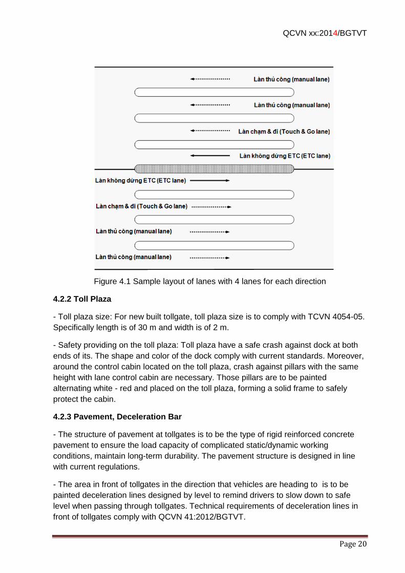
QCVN xx:2014/BGTVT
Page 20
Figure 4.1 Sample layout of lanes with 4 lanes for each direction
4.2.2 Toll Plaza
- Toll plaza size: For new built tollgate, toll plaza size is to comply with TCVN 4054-05.
Specifically length is of 30 m and width is of 2 m.
- Safety providing on the toll plaza: Toll plaza have a safe crash against dock at both
ends of its. The shape and color of the dock comply with current standards. Moreover,
around the control cabin located on the toll plaza, crash against pillars with the same
height with lane control cabin are necessary. Those pillars are to be painted
alternating white - red and placed on the toll plaza, forming a solid frame to safely
protect the cabin.
4.2.3 Pavement, Deceleration Bar
- The structure of pavement at tollgates is to be the type of rigid reinforced concrete
pavement to ensure the load capacity of complicated static/dynamic working
conditions, maintain long-term durability. The pavement structure is designed in line
with current regulations.
- The area in front of tollgates in the direction that vehicles are heading to is to be
painted deceleration lines designed by level to remind drivers to slow down to safe
level when passing through tollgates. Technical requirements of deceleration lines in
front of tollgates comply with QCVN 41:2012/BGTVT.
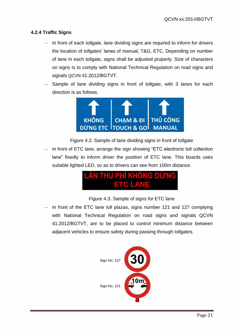
QCVN xx:2014/BGTVT
Page 21
4.2.4 Traffic Signs
In front of each tollgate, lane dividing signs are required to inform for drivers
the location of tollgates’ lanes of manual, T&G, ETC. Depending on number
of lane in each tollgate, signs shall be adjusted properly. Size of characters
on signs is to comply with National Technical Regulation on road signs and
signals QCVN 41:2012/BGTVT.
Sample of lane dividing signs in front of tollgate, with 3 lanes for each
direction is as follows.
KHÔNG DỪNG ETC
CHẠM & ĐITOUCH & GO
THỦ CÔNGMANUAL
Figure 4.2. Sample of lane dividing signs in front of tollgate
In front of ETC lane, arrange the sign showing “ETC electronic toll collection
lane” fixedly to inform driver the position of ETC lane. This boards uses
suitable lighted LED, so as to drivers can see from 100m distance.
LÀN THU PHÍ KHÔNG DỪNG
ETC
Figure 4.3. Sample of signs for ETC lane
In front of the ETC lane toll plazas, signs number 121 and 127 complying
with National Technical Regulation on road signs and signals QCVN
41:2012/BGTVT, are to be placed to control minimum distance between
adjacent vehicles to ensure safety during passing through tollgates.
ETC LANE
Sign No. 127
Sign No. 121
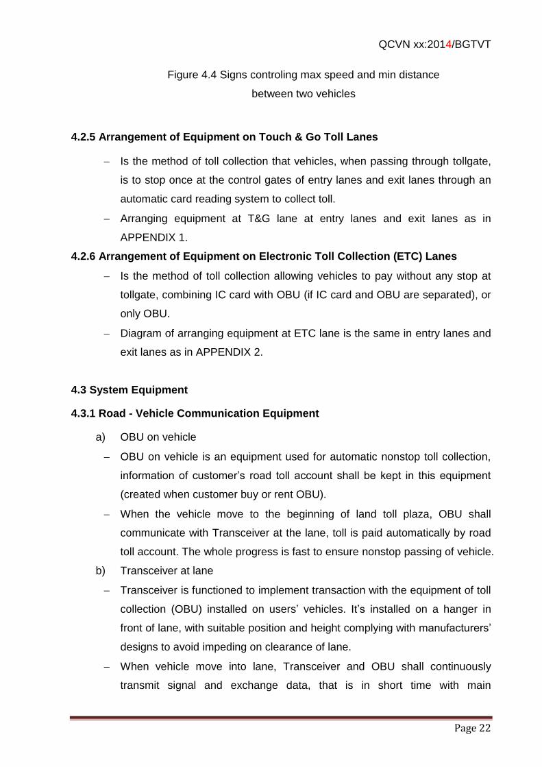
QCVN xx:2014/BGTVT
Page 22
Figure 4.4 Signs controling max speed and min distance
between two vehicles
4.2.5 Arrangement of Equipment on Touch & Go Toll Lanes
Is the method of toll collection that vehicles, when passing through tollgate,
is to stop once at the control gates of entry lanes and exit lanes through an
automatic card reading system to collect toll.
Arranging equipment at T&G lane at entry lanes and exit lanes as in
APPENDIX 1.
4.2.6 Arrangement of Equipment on Electronic Toll Collection (ETC) Lanes
Is the method of toll collection allowing vehicles to pay without any stop at
tollgate, combining IC card with OBU (if IC card and OBU are separated), or
only OBU.
Diagram of arranging equipment at ETC lane is the same in entry lanes and
exit lanes as in APPENDIX 2.
4.3 System Equipment
4.3.1 Road - Vehicle Communication Equipment
a) OBU on vehicle
OBU on vehicle is an equipment used for automatic nonstop toll collection,
information of customer’s road toll account shall be kept in this equipment
(created when customer buy or rent OBU).
When the vehicle move to the beginning of land toll plaza, OBU shall
communicate with Transceiver at the lane, toll is paid automatically by road
toll account. The whole progress is fast to ensure nonstop passing of vehicle.
b) Transceiver at lane
Transceiver is functioned to implement transaction with the equipment of toll
collection (OBU) installed on users’ vehicles. It’s installed on a hanger in
front of lane, with suitable position and height complying with manufacturers’
designs to avoid impeding on clearance of lane.
When vehicle move into lane, Transceiver and OBU shall continuously
transmit signal and exchange data, that is in short time with main
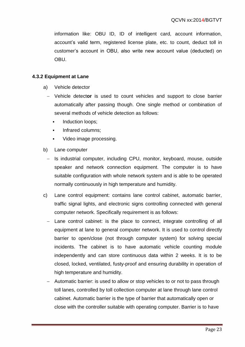
QCVN xx:2014/BGTVT
Page 23
information like: OBU ID, ID of intelligent card, account information,
account’s valid term, registered license plate, etc. to count, deduct toll in
customer’s account in OBU, also write new account value (deducted) on
OBU.
4.3.2 Equipment at Lane
a) Vehicle detector
Vehicle detector is used to count vehicles and support to close barrier
automatically after passing though. One single method or combination of
several methods of vehicle detection as follows:
Induction loops;
Infrared columns;
Video image processing.
b) Lane computer
Is industrial computer, including CPU, monitor, keyboard, mouse, outside
speaker and network connection equipment. The computer is to have
suitable configuration with whole network system and is able to be operated
normally continuously in high temperature and humidity.
c) Lane control equipment: contains lane control cabinet, automatic barrier,
traffic signal lights, and electronic signs controlling connected with general
computer network. Specifically requirement is as follows:
Lane control cabinet: is the place to connect, integrate controlling of all
equipment at lane to general computer network. It is used to control directly
barrier to open/close (not through computer system) for solving special
incidents. The cabinet is to have automatic vehicle counting module
independently and can store continuous data within 2 weeks. It is to be
closed, locked, ventilated, fusty-proof and ensuring durability in operation of
high temperature and humidity.
Automatic barrier: is used to allow or stop vehicles to or not to pass through
toll lanes, controlled by toll collection computer at lane through lane control
cabinet. Automatic barrier is the type of barrier that automatically open or
close with the controller suitable with operating computer. Barrier is to have
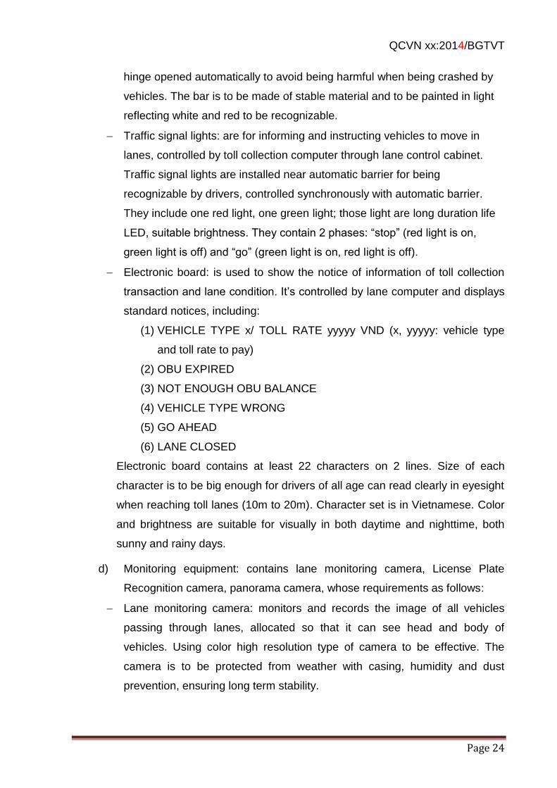
QCVN xx:2014/BGTVT
Page 24
hinge opened automatically to avoid being harmful when being crashed by
vehicles. The bar is to be made of stable material and to be painted in light
reflecting white and red to be recognizable.
Traffic signal lights: are for informing and instructing vehicles to move in
lanes, controlled by toll collection computer through lane control cabinet.
Traffic signal lights are installed near automatic barrier for being
recognizable by drivers, controlled synchronously with automatic barrier.
They include one red light, one green light; those light are long duration life
LED, suitable brightness. They contain 2 phases: “stop” (red light is on,
green light is off) and “go” (green light is on, red light is off).
Electronic board: is used to show the notice of information of toll collection
transaction and lane condition. It’s controlled by lane computer and displays
standard notices, including:
(1) VEHICLE TYPE x/ TOLL RATE yyyyy VND (x, yyyyy: vehicle type
and toll rate to pay)
(2) OBU EXPIRED
(3) NOT ENOUGH OBU BALANCE
(4) VEHICLE TYPE WRONG
(5) GO AHEAD
(6) LANE CLOSED
Electronic board contains at least 22 characters on 2 lines. Size of each
character is to be big enough for drivers of all age can read clearly in eyesight
when reaching toll lanes (10m to 20m). Character set is in Vietnamese. Color
and brightness are suitable for visually in both daytime and nighttime, both
sunny and rainy days.
d) Monitoring equipment: contains lane monitoring camera, License Plate
Recognition camera, panorama camera, whose requirements as follows:
Lane monitoring camera: monitors and records the image of all vehicles
passing through lanes, allocated so that it can see head and body of
vehicles. Using color high resolution type of camera to be effective. The
camera is to be protected from weather with casing, humidity and dust
prevention, ensuring long term stability.
QCVN xx:2014/BGTVT
Page 25
License Plate Recognition camera: for capturing license plate when vehicle
entering toll collection lane, automatically provide for license plate detecting
software whose result of data shall be compared with those on OBU. This
process support monitoring, post auditing of vehicles passing through toll
lane. Camera for Recognition of License Plate is a specialized camera for
license plate recognition by computer reach high accuracy, in both daytime
and nighttime. It’s to be located at proper locations to capture license plates
clearly.
Panorama camera: All history and status of tollgate is monitored by road
operator through panorama camera. Thanks to it, monitoring person can
give out comments to device suitable flow, avoiding traffic congestion.
Camera is to have casing for weather (sunlight, rain, dust) protection;
zooming glass for observing clearly half of tollgate activities, is able to
monitor both daytime and nighttime. Camera location is to be chosen the
most effective ones.
e) Other equipment: manual barrier, toll plaza front indicator light, lane status
indicator light, whistle and alarm light, UPS, specifically required as follows:
Manual barrier: a type of stop bar in front of lane, opened/closed manually,
preventing vehicles from entering when the volume is low or serving for
checking, maintenance, repairing. On the barrier, prohibit sign is to be
installed (Sign number 101 of QCVN 41:2012/BGTVT) with reduced size of
0.6 to 0.8 basic sign’s size. At the hinge, it’s necessary to fit an automatic
switch of lane close/open lighting line with status of lane opening so as to be
proper with the status between barrier and flash lights. Moreover, in order to
reduce occupying space of open-barrier (less occupying space on toll
plaza); fold hinge is needed to reduce the length of barrier.
Toll plaza front indicator light: is for alarming obstacle for vehicle owners in
bad weather, unclear vision, installed in front of lane toll plaza. To do that,
light is designed with continuous yellow flash light to attract drivers. The
brightness is moderate to avoid flaring at night.
Lane status indicator light: is for informing lane status being close/open (or
function/stop). It’s located on tollgate’s roof, the vehicle coming direction. It
contains two phases: “closed”, in equivalent with X red lamp, and “opened”, in
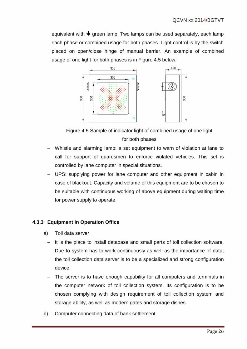
QCVN xx:2014/BGTVT
Page 26
equivalent with green lamp. Two lamps can be used separately, each lamp
each phase or combined usage for both phases. Light control is by the switch
placed on open/close hinge of manual barrier. An example of combined
usage of one light for both phases is in Figure 4.5 below:
Figure 4.5 Sample of indicator light of combined usage of one light
for both phases
Whistle and alarming lamp: a set equipment to warn of violation at lane to
call for support of guardsmen to enforce violated vehicles. This set is
controlled by lane computer in special situations.
UPS: supplying power for lane computer and other equipment in cabin in
case of blackout. Capacity and volume of this equipment are to be chosen to
be suitable with continuous working of above equipment during waiting time
for power supply to operate.
4.3.3 Equipment in Operation Office
a) Toll data server
It is the place to install database and small parts of toll collection software.
Due to system has to work continuously as well as the importance of data;
the toll collection data server is to be a specialized and strong configuration
device.
The server is to have enough capability for all computers and terminals in
the computer network of toll collection system. Its configuration is to be
chosen complying with design requirement of toll collection system and
storage ability, as well as modern gates and storage dishes.
b) Computer connecting data of bank settlement
QCVN xx:2014/BGTVT
Page 27
Serving for toll collection data connection at tollgate with bank settlement
system. Computers are to be chosen the type of suitable stability and
quantity, to ensure reliability and stability.
c) Other equipment
- Monitoring computer: contain monitoring and post auditing program for
operation staffs, monitoring toll collection activities at tollgates as well as
post auditing for unusual matters, reducing negatives. Number of monitoring
computers depends on number of lanes. Monitoring computer is to be one
set monitor, printer, and supplement devices, connected with internet.
Configuration is to be chosen complying with design requirement of toll
collection system and image processing capability is to be higher. For
stability, it’s required to choosing the type that can work continuously and
long-term. Monitor's size is at least 17 inch and high resolution for clear
vision and avoiding eye tiredness for monitoring person
Data storage device: can be provided additionally to widen system's
possibility of storing data and image. The latest and most popular
technology should be taken, but, ensuring safe and long term storage. It's
necessary to consider fixed storage capacity for storage device to ensure
storage possibility before changing into storage CDs or tapes.
Digital recorder: Allocated in operation room, serving for recording of lane
cameras, panorama cameras, and other cameras in operation room.
Monitor: Monitor in center is to be the type that of compatible digital image
signals, suitable with monitoring equipment system's output signal which has
been processed. It's in the size of at least 32 inches, high resolution to be
easily observed.
Minimum specifications of main equipment is as in APPENDIX 5
4.3.4 Supplement Equipment System
Other supplement equipment such as: lightning prevention system, internal
communication system, backup generator, UPS, fire prevention system are
stipulated and are to comply with related regulations.
4.3.5 Reliability and Backup Equipment
QCVN xx:2014/BGTVT
Page 28
Toll collection system is operated 24/24, therefore it's required to have high
reliability and have suitable backup equipment to ensure continuous
operation, not causing stop of the whole system.
4.3.6 Network System and Transmission Line
Network equipment system and transmission line are to comply with total
system and compatible with other system equipment. Connection plugs are
to ensure durability and safety. Connection boxes are close and fire
prevention. Also network equipment system and transmission line are to be
designed with open feature to be available to connect with bank settlement
center, bank control center, section and regional management offices
(centers) by current regulations.
4.3.7 Power Supply System
Power supply system is to be industrial 3 phase one (3 phases, 4 lines),
sufficient capacity with each tollgate, and other specific supplement system
on expressway and to comply with current regulations.
4.4 System Software
4.4.1 General Requirement
Software system is to meet the requirements in above toll collection
functions, meet requirements on operation and situations of toll collection
procedure (T&G and ETC. Software is to connect controlling all system of
equipment including computer network equipment, lane control equipment,
monitoring equipment of various kinds, etc. as mentioned above. It’s
recommended to apply new automatic technology in human-machine
interface and dialogue as well as other preeminent functions. Software
system is to be able to independently work when losing connection with the
server.
Besides, it is to have other functions as: transmitting and exchanging all toll
collection data to expressway operation centers, section and regional
management centers, bank control center for executing management,
control and other operations.
QCVN xx:2014/BGTVT
Page 29
4.4.2 Processing Software at Lane
Processing software at toll lane is installed on lane computer; the software shall
operate and solve situations of the procedures for manual; T&G, ETC toll
collection. Moreover, software at T&G, ETC toll collection lanes is to be added
following automatic capabilities:
Reading and writing data on IC-Card, or OBU, check the validity of IC card
or OBU
Controlling equipment system at automatic toll collection lane
Capturing vehicle entering automatic toll collection lane
License plate Recognition or categorized type of vehicle
Providing signals and OBU control information to operation center
Moreover, the software is to meet with processing requirement for the following
situations:
Vehicle with valid OBU
Vehicle with insufficient balance OBU or locked OBU
Vehicle with OBU but can’t communicate
Vehicle without OBU or with wrong OBU entering lane
Independently operation capability when losing connection with operation
center
4.4.3 Management Software in Center at Tollgate
Management software in center is the combination of software or software
modules installed on toll collection data servers and computers in operation office.
This software is to contain modules functioning as follows:
Manage, copy toll collection data
Report, statistic: Provide Reports, statistics of system operation
Accounting: the purpose is to manage and control accounting activities,
serving for accounting business. Supporting management, storage in and
selling of OBU, as well as stocking, reports.
Monitoring, post auditing: provide functions to Monitor and post auditing toll
collection transaction as well as toll collection staffs
Sending information, data from main center to toll lane and settlement units
QCVN xx:2014/BGTVT
Page 30
Security: managing security function such as : password, group of
passwords, orders, demarcration. For storage data, data security is
executed by 5 following levels:
(1) Toll collection staff
(2) Monitoring person, technical person, accountant
(3) Shift head, tollgate leader
(4) Inspector/company’s director,
(5) Top head
4.4.4 Software Connecting Settlement/Control through Bank
Software connecting bank settlement/control between bank settlement and
ETC toll collection at tollgate, with following functions: Connecting toll
payment services for traffic on expressways for users through bank account.
Processing toll collection transactions as well as the operations associated
(control, toll revenue settlement ...). Saving transactions and exchanging
information with tollgates. Comparing revenue report and transaction data
betwee tollgates and bank system; assuring the security communication in the
connection from banks to tollgates.
Synchronization of data between bank settment server at bank and ETC toll
collection system server at tollgate is done periodically (offline), priority level
belongs to each data flow and PUSH scheme (the side obtaining data to be
synchronized shall positively push data to the receiver).
All data executed and processed at bank settlement system and server of
ETC toll collection is blog stored during exchange, serving for information
exploitation for reports, evidence when there is any dispute.
Beside, software also has the functions of connecting to and sharing toll
collection data with the server at section and regional management centers to
generate data in use in management according to regulations. Section and
regional management centers are capable to send query or register of receiving
toll collection information reports by day including: section, time, the number of
vehicles and toll amount defined by section, vehicle type; numbers vehicles
applied electronic toll collection according to current regulations.
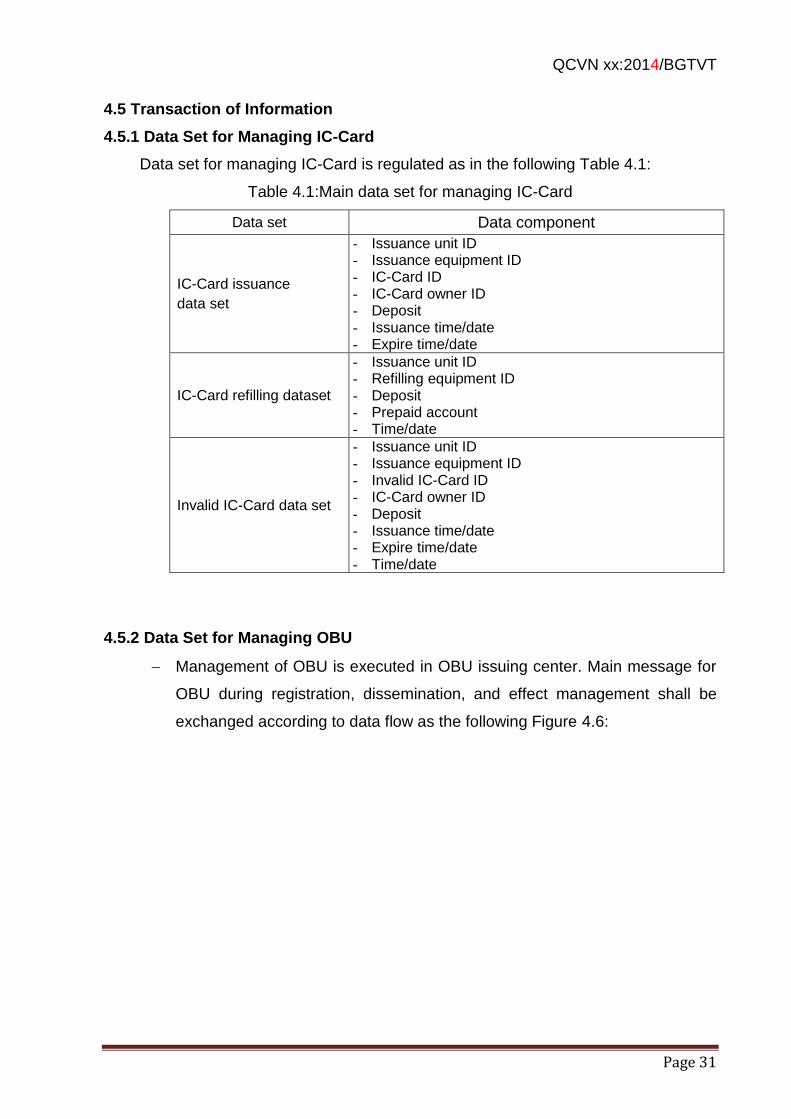
QCVN xx:2014/BGTVT
Page 31
4.5 Transaction of Information
4.5.1 Data Set for Managing IC-Card
Data set for managing IC-Card is regulated as in the following Table 4.1:
Table 4.1:Main data set for managing IC-Card
Data set Data component
IC-Card issuance
data set
- Issuance unit ID - Issuance equipment ID - IC-Card ID - IC-Card owner ID - Deposit - Issuance time/date - Expire time/date
IC-Card refilling dataset
- Issuance unit ID - Refilling equipment ID - Deposit - Prepaid account - Time/date
Invalid IC-Card data set
- Issuance unit ID - Issuance equipment ID - Invalid IC-Card ID - IC-Card owner ID - Deposit - Issuance time/date - Expire time/date - Time/date
4.5.2 Data Set for Managing OBU
Management of OBU is executed in OBU issuing center. Main message for
OBU during registration, dissemination, and effect management shall be
exchanged according to data flow as the following Figure 4.6:
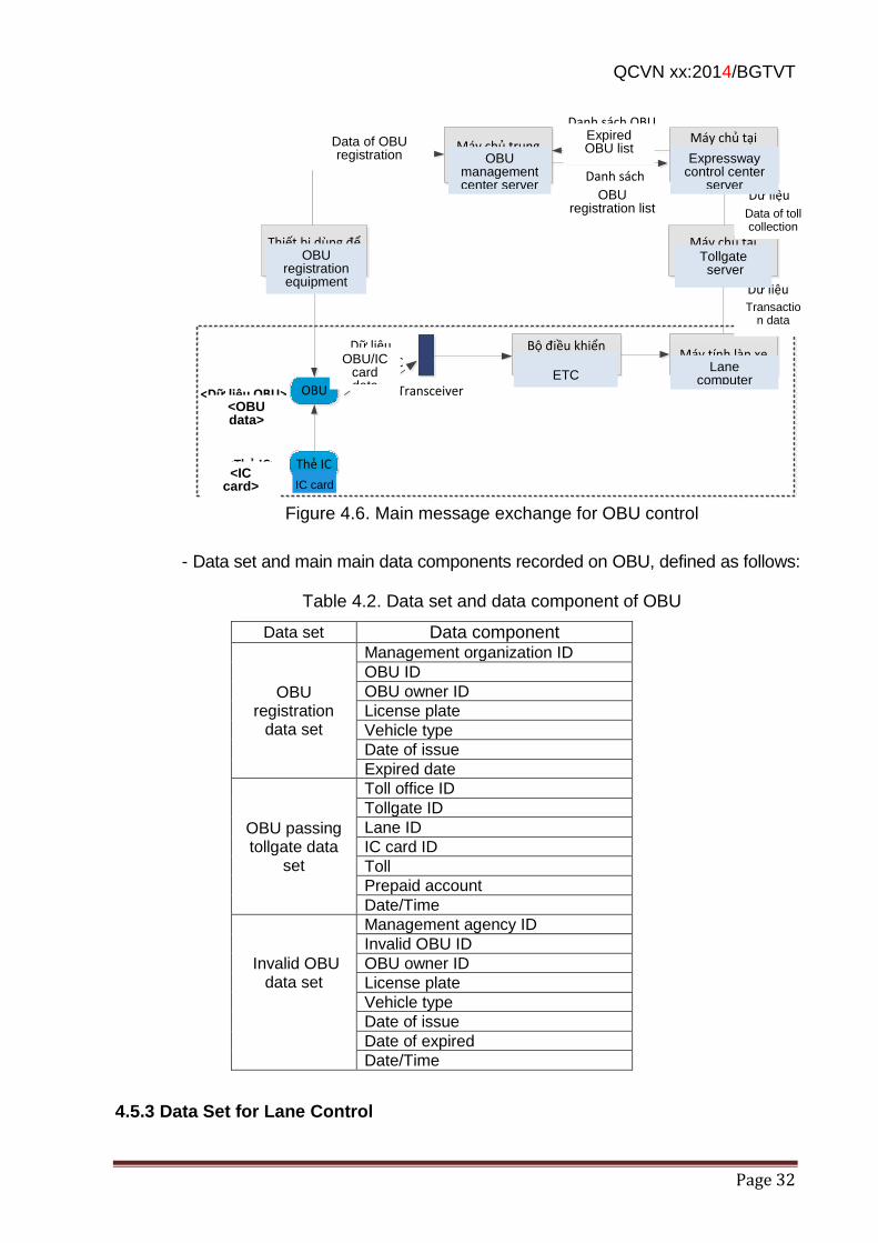
QCVN xx:2014/BGTVT
Page 32
Bộ điều khiển ETC
Máy tính làn xe
Máy chủ tại trạm thu phí
Thẻ IC<Thẻ IC>
<Dữ liệu OBU>
Máy chủ trung tâm quản lý OBU
Danh sách đăng ký OBU
Dữ liệu Giao dịch
Dữ liệu Thu phí
Transceiver
Dữ liệu OBU/thẻ IC
OBU
Máy chủ tại trung tâm
điều hành cao tốc
Danh sách OBU hết hiệu lực
Thiết bị dùng để đăng ký OBU
Dữ liệu đăng ký OBU
Figure 4.6. Main message exchange for OBU control
- Data set and main main data components recorded on OBU, defined as follows:
Table 4.2. Data set and data component of OBU
Data set Data component
OBU registration
data set
Management organization ID
OBU ID
OBU owner ID
License plate
Vehicle type
Date of issue
Expired date
OBU passing tollgate data
set
Toll office ID
Tollgate ID
Lane ID
IC card ID
Toll
Prepaid account
Date/Time
Invalid OBU data set
Management agency ID
Invalid OBU ID
OBU owner ID
License plate
Vehicle type
Date of issue
Date of expired
Date/Time
4.5.3 Data Set for Lane Control
OBU management center server
Expressway control center
server
Tollgate server
OBU registration equipment
ETC
controller
Lane computer
IC card
OBU/IC card data
<OBU data>
<IC card>
Transaction data
Data of toll collection
Expired OBU list
OBU registration list
Data of OBU registration
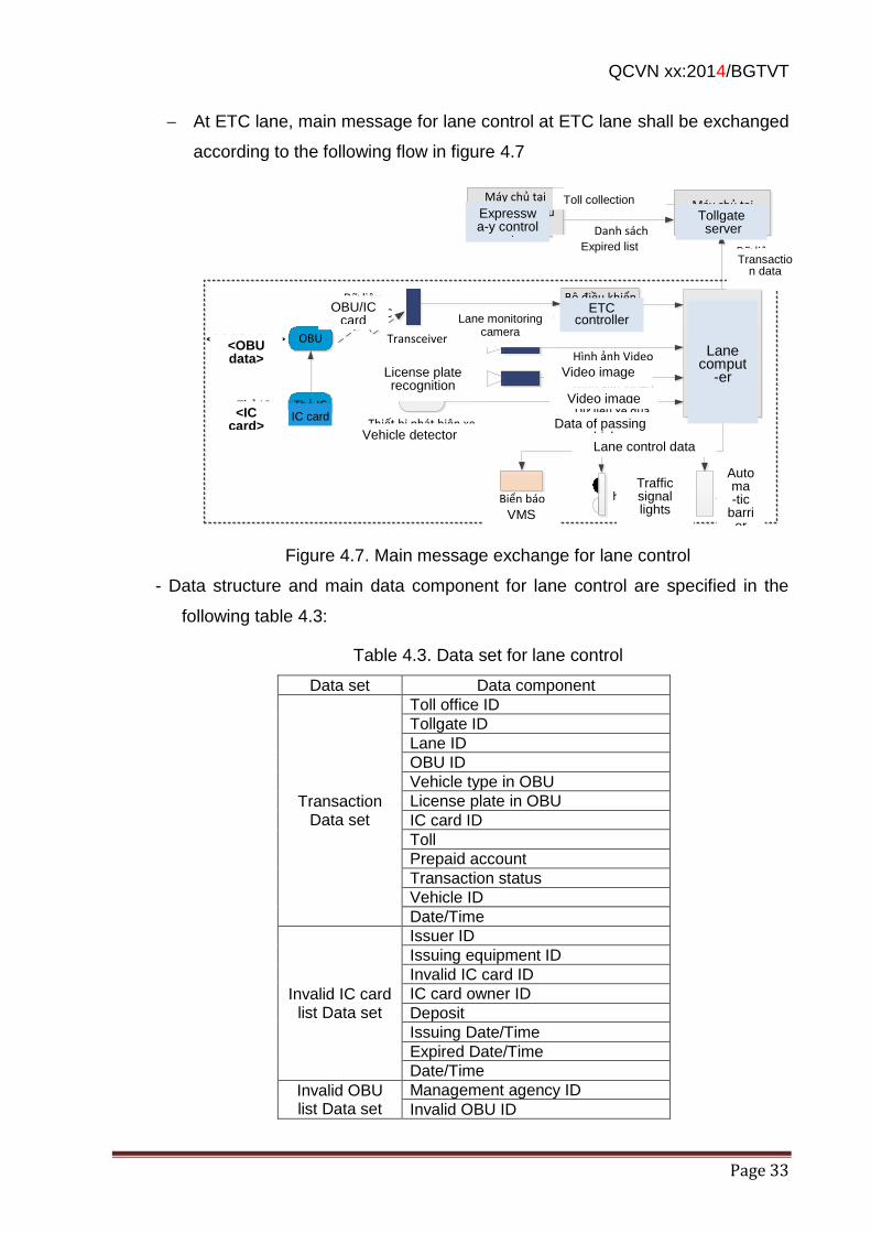
QCVN xx:2014/BGTVT
Page 33
At ETC lane, main message for lane control at ETC lane shall be exchanged
according to the following flow in figure 4.7
Bộ điều khiểnETC
Máy tính làn xe
Máy chủ tại trạm thu phí
Thẻ IC<Thẻ IC>
<Dữ liệu OBU>
Hình ảnh VideoCamera nhận dạng biển số
Dữ liệu xe qua
Dữ liệu Giao dịch
Dữ liệu Thu phí
Transceiver
Thiết bị phát hiện xe
Dữ liệu OBU/thẻ IC
OBU
Hình ảnh Video
Máy chủ tại trung tâm điều hành cao tốc
Camera quan sát làn xe
Danh sách hết hiệu lực
Biển báoĐiện tử
Dữ liệu kiểm soát làn xe
Ba-ri-eTự động
Đèn tín hiệu giao
thông
Figure 4.7. Main message exchange for lane control
- Data structure and main data component for lane control are specified in the
following table 4.3:
Table 4.3. Data set for lane control
Data set Data component
Transaction Data set
Toll office ID
Tollgate ID
Lane ID
OBU ID
Vehicle type in OBU
License plate in OBU
IC card ID
Toll
Prepaid account
Transaction status
Vehicle ID
Date/Time
Invalid IC card list Data set
Issuer ID
Issuing equipment ID
Invalid IC card ID
IC card owner ID
Deposit
Issuing Date/Time
Expired Date/Time
Date/Time
Invalid OBU list Data set
Management agency ID
Invalid OBU ID
Expresswa-y control
center server
Lane comput
-er
ETC controller
IC card
OBU/IC card data
<OBU data>
<IC card>
Transaction data
Lane monitoring camera
Video image License plate recognition
camera Video image
Lane control data
Data of passing vehicle Vehicle detector
VMS
Traffic signal lights
Automa -tic
barrier
Tollgate server
Toll collection data
Expired list
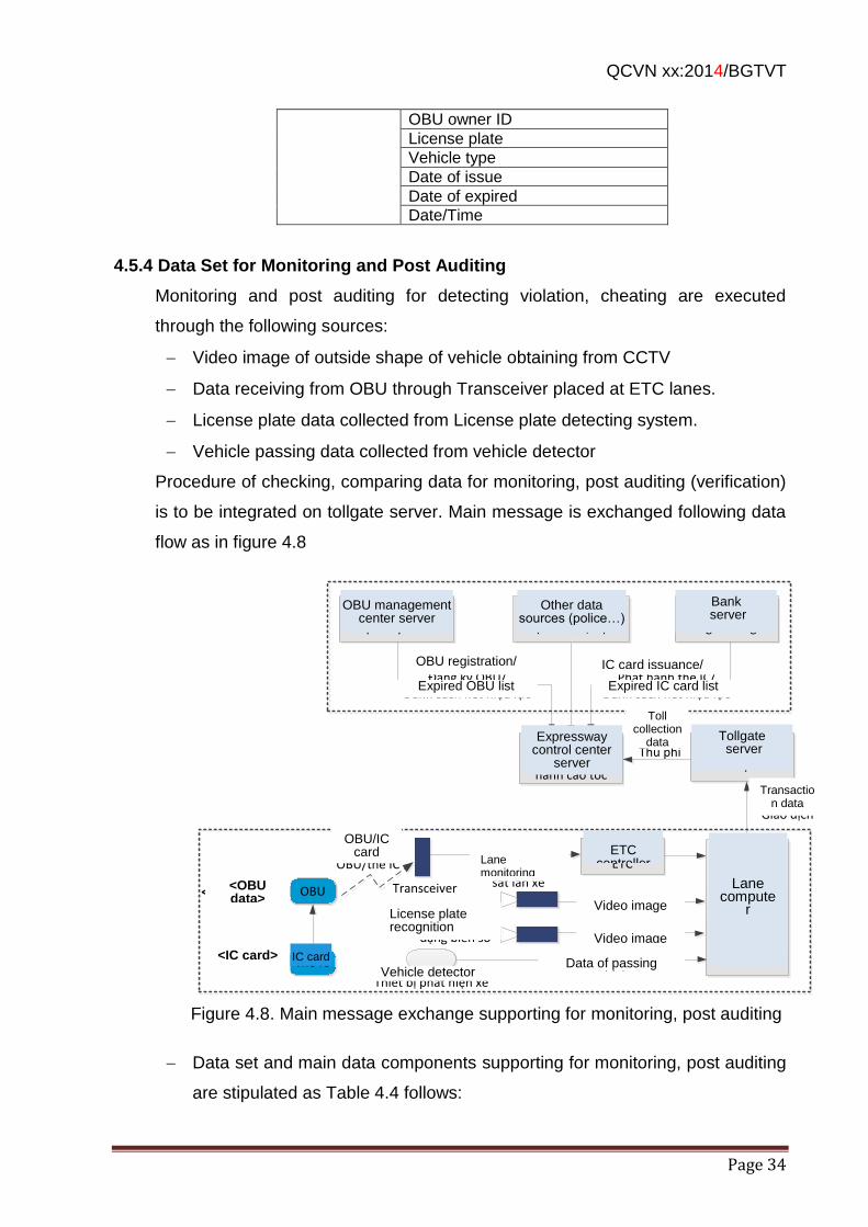
QCVN xx:2014/BGTVT
Page 34
OBU owner ID
License plate
Vehicle type
Date of issue
Date of expired
Date/Time
4.5.4 Data Set for Monitoring and Post Auditing
Monitoring and post auditing for detecting violation, cheating are executed
through the following sources:
Video image of outside shape of vehicle obtaining from CCTV
Data receiving from OBU through Transceiver placed at ETC lanes.
License plate data collected from License plate detecting system.
Vehicle passing data collected from vehicle detector
Procedure of checking, comparing data for monitoring, post auditing (verification)
is to be integrated on tollgate server. Main message is exchanged following data
flow as in figure 4.8
Bộ điều khiểnETC
Máy tính làn xe
Máy chủ tại trạm thu phí
Thẻ IC<Thẻ IC>
<Dữ liệu OBU>
Máy chủNgân hàng
Máy chủ trung tâm quản lý OBU
Nguồn dữ liệu khác (cảnh sát, …)
Hình ảnh VideoCamera nhận dạng biển số
Dữ liệu xe qua
Phát hành thẻ IC/Danh sách hết hiệu lực
Dữ liệu Giao dịch
Dữ liệu Thu phí
Transceiver
Thiết bị phát hiện xe
Dữ liệu OBU/thẻ IC
OBU
Hình ảnh Video
Máy chủ tại trung tâm điều hành cao tốc
Camera quan sát làn xe
Đăng ký OBU/Danh sách hết hiệu lực
Figure 4.8. Main message exchange supporting for monitoring, post auditing
Data set and main data components supporting for monitoring, post auditing
are stipulated as Table 4.4 follows:
Expressway control center
server
Lane compute
r
OBU/IC card data
<OBU data>
<IC card>
Transaction data
Lane monitoring camera
Video image License plate recognition camera
Data of passing vehicle Vehicle detector
Tollgate server
Toll collection
data
Video image
OBU management center server
Other data sources (police…)
Bank server
OBU registration/
Expired OBU list
IC card issuance/
Expired IC card list
ETC
controller
IC card
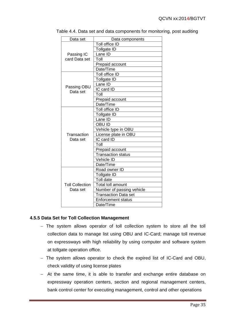
QCVN xx:2014/BGTVT
Page 35
Table 4.4. Data set and data components for monitoring, post auditing
Data set Data components
Passing IC card Data set
Toll office ID
Tollgate ID
Lane ID
Toll
Prepaid account
Date/Time
Passing OBU Data set
Toll office ID
Tollgate ID
Lane ID
IC card ID
Toll
Prepaid account
Date/Time
Transaction Data set
Toll office ID
Tollgate ID
Lane ID
OBU ID
Vehicle type in OBU
License plate in OBU
IC card ID
Toll
Prepaid account
Transaction status
Vehicle ID
Date/Time
Toll Collection Data set
Road owner ID
Tollgate ID
Toll date
Total toll amount
Number of passing vehicle
Transaction Data set
Enforcement status
Date/Time
4.5.5 Data Set for Toll Collection Management
The system allows operator of toll collection system to store all the toll
collection data to manage list using OBU and IC-Card; manage toll revenue
on expressways with high reliability by using computer and software system
at tollgate operation office.
The system allows operator to check the expired list of IC-Card and OBU,
check validity of using license plates
At the same time, it is able to transfer and exchange entire database on
expressway operation centers, section and regional management centers,
bank control center for executing management, control and other operations
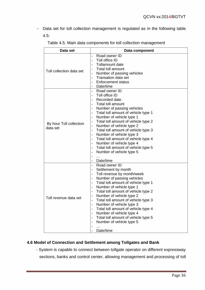
QCVN xx:2014/BGTVT
Page 36
Data set for toll collection management is regulated as in the following table
4.5:
Table 4.5. Main data components for toll collection management
Data set Data component
Toll collection data set
- Road owner ID - Toll office ID - Tollamount date - Total toll amount - Number of passing vehicles - Transation data set - Enforcement status - Date/time
By hour Toll collection data set
- Road owner ID - Toll office ID - Recorded date - Total toll amount - Number of passing vehicles - Total toll amount of vehicle type 1 - Number of vehicle type 1 - Total toll amount of vehicle type 2 - Number of vehicle type 2 - Total toll amount of vehicle type 3 - Number of vehicle type 3 - Total toll amount of vehicle type 4 - Number of vehicle type 4 - Total toll amount of vehicle type 5 - Number of vehicle type 5 - … - Date/time
Toll revenue data set
- Road owner ID - Settlement by month - Toll revenue by month/week - Number of passing vehicles - Total toll amount of vehicle type 1 - Number of vehicle type 1 - Total toll amount of vehicle type 2 - Number of vehicle type 2 - Total toll amount of vehicle type 3 - Number of vehicle type 3 - Total toll amount of vehicle type 4 - Number of vehicle type 4 - Total toll amount of vehicle type 5 - Number of vehicle type 5 - … - Date/time
4.6 Model of Connection and Settlement among Tollgates and Bank
- System is capable to connect between tollgate operator on different expressway
sections, banks and control center, allowing management and processing of toll
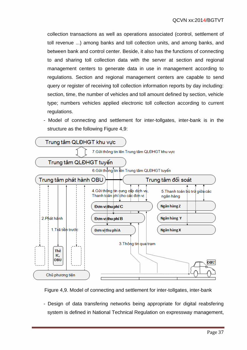
QCVN xx:2014/BGTVT
Page 37
collection transactions as well as operations associated (control, settlement of
toll revenue ...) among banks and toll collection units, and among banks, and
between bank and control center. Beside, it also has the functions of connecting
to and sharing toll collection data with the server at section and regional
management centers to generate data in use in management according to
regulations. Section and regional management centers are capable to send
query or register of receiving toll collection information reports by day including:
section, time, the number of vehicles and toll amount defined by section, vehicle
type; numbers vehicles applied electronic toll collection according to current
regulations.
- Model of connecting and settlement for inter-tollgates, inter-bank is in the
structure as the following Figure 4,9:
Figure 4,9. Model of connecting and settlement for inter-tollgates, inter-bank
- Design of data transfering networks being appropriate for digital reabsfering
system is defined in National Technical Regulation on expressway management,
QCVN xx:2014/BGTVT
Page 38
monitoring and control system.
- VLAN division is set up to devide types the transmision network and various
equipment groups in network system.
- Firewall device system devices needs to be used to ensure security for connecting
out to Internet.
- Other regulations on structure of transmision network and transmission standard
among centers are required to comply with current related regulations.
QCVN xx:2014/BGTVT
Page 39
5. REGULATIONS ON REPORTS
Standard reports are to be extracted by requirement for management and check,
inspection for electronic toll collection on the whole nationwide expressways,
including:
Collective toll collection report at center
List sheet of collective 1 part of toll collection ticket at tollgate
Center Toll collection report (by the receipt quantity)
Statistic of vehicle volume of lane passing
Beside, other reports complying with quality of each tollgate and expressway may
included, such as : staff shift handling over report, collective handling over report,
nationwide free vehicle report and ticket vehicle report. Detail report samples are
in APPENDIX 6.
6. REGULATIONS ON MANAGEMENT
Toll management, usage and accounting are applied according to Article 8,
Circular No. 159/2013/TT-BTC dated 14/11/2013 of the Ministry of Finance
guiding the regime of collection, payment, management and road usage toll for
ROI (Return On Investment) of road construction.
Toll collection invoice and receipts are applied according to Article 9, Circular No.
159/2013/TT-BTC dated 14/11/2013 of the Ministry of Finance guiding the regime
of collection, payment, management and road usage toll for ROI (Return On
Investment) of road construction.
Electronic toll collection system on the entire of expressways shall be managed,
exploited and operated by the invester or road operator, operator maintenance
organization under regulations of competent agency.
Expressway management agency under Ministry of Transport is to be
responsible for management, monitoring the investment construction and
operation Electronic toll collection system on the entire of expressways in its
authorities.
Connection between toll collection operation center, section management center,
regional management center is executed under the roadmap and instruction by
expressway management agency.
QCVN xx:2014/BGTVT
Page 40
7. IMPLEMENTATION
Organizations, individuals related to planning of development, construction
investment, management, operation, and maintennance of tollgates that have
electronic toll collection lane, are to follow regulations in this specifications and
other related documents.
In case specifications, standards, technical documents mantioned in 1.4 of this
specifications may change, with supplement or replacement, follow the latest one.
DRVN is responsible for building up general procedure on ETC operation and
maintenance as a base for building the detail operation and maintenance
procedure for each tollgate.
DRVN chair, cooperate with Department of Infrastructure, Department of Science
and Technilogy (MOT) and other functional agencies to instruct implementation
and organization of excuting this regulation.
APPENDIX 1: Sample of arranging equipment on T&G toll lane
Sample of arranging equipment on T&G toll lane is as the following figure:
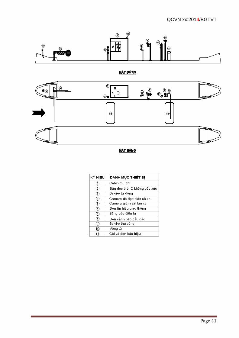
QCVN xx:2014/BGTVT
Page 41
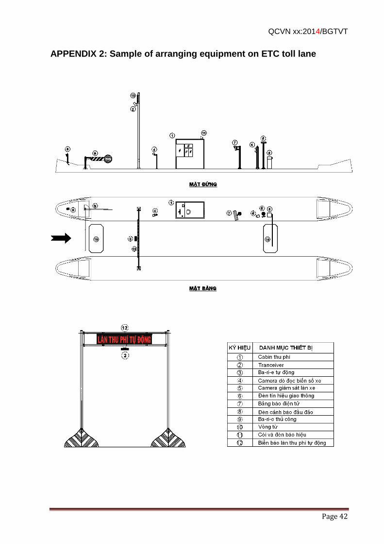
QCVN xx:2014/BGTVT
Page 42
APPENDIX 2: Sample of arranging equipment on ETC toll lane
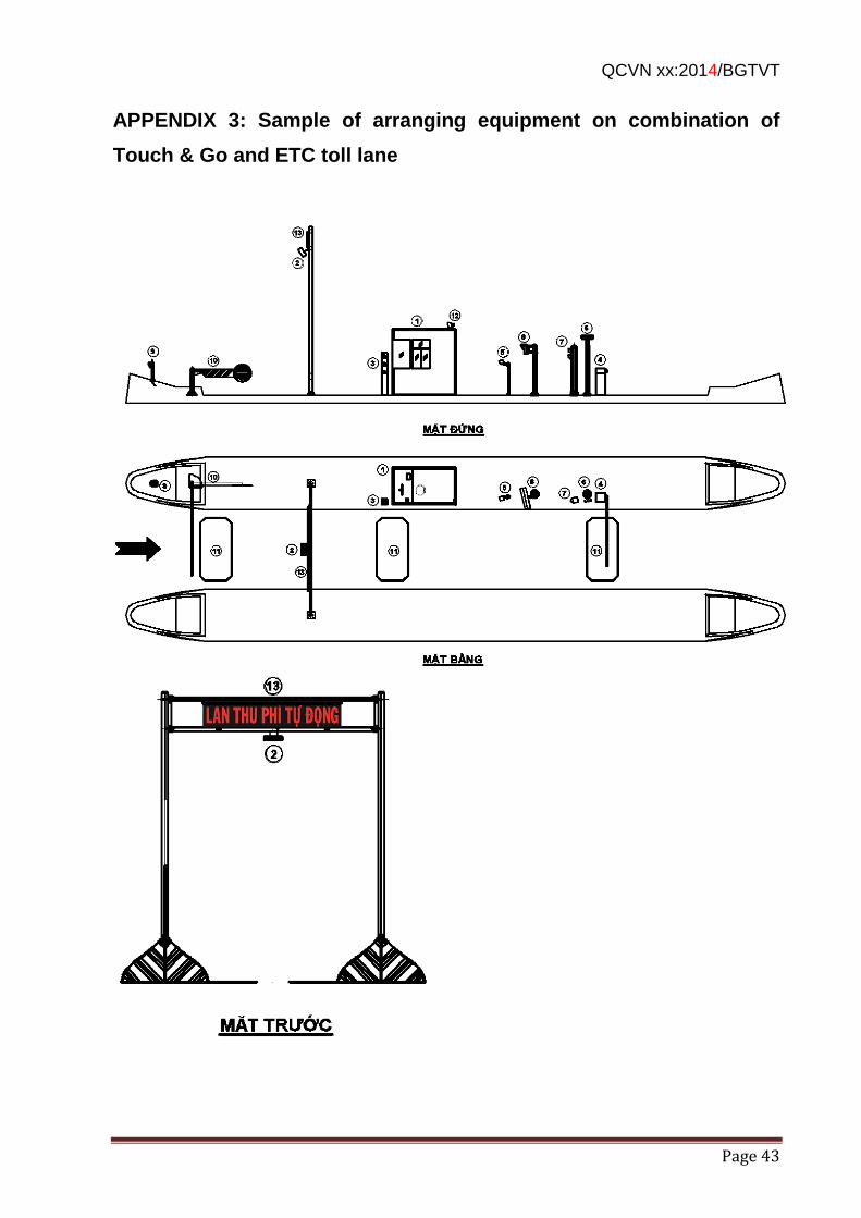
QCVN xx:2014/BGTVT
Page 43
APPENDIX 3: Sample of arranging equipment on combination of
Touch & Go and ETC toll lane
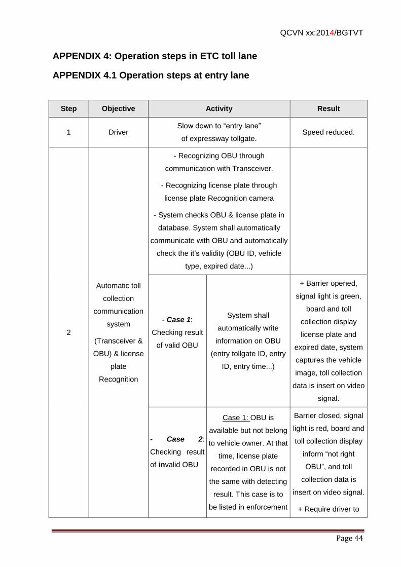
QCVN xx:2014/BGTVT
Page 44
APPENDIX 4: Operation steps in ETC toll lane
APPENDIX 4.1 Operation steps at entry lane
Step Objective Activity Result
1 Driver Slow down to “entry lane”
of expressway tollgate. Speed reduced.
2
Automatic toll
collection
communication
system
(Transceiver &
OBU) & license
plate
Recognition
- Recognizing OBU through
communication with Transceiver.
- Recognizing license plate through
license plate Recognition camera
- System checks OBU & license plate in
database. System shall automatically
communicate with OBU and automatically
check the it’s validity (OBU ID, vehicle
type, expired date...)
- Case 1:
Checking result
of valid OBU
System shall
automatically write
information on OBU
(entry tollgate ID, entry
ID, entry time...)
+ Barrier opened,
signal light is green,
board and toll
collection display
license plate and
expired date, system
captures the vehicle
image, toll collection
data is insert on video
signal.
- Case 2:
Checking result
of invalid OBU
Case 1: OBU is
available but not belong
to vehicle owner. At that
time, license plate
recorded in OBU is not
the same with detecting
result. This case is to
be listed in enforcement
Barrier closed, signal
light is red, board and
toll collection display
inform “not right
OBU”, and toll
collection data is
insert on video signal.
+ Require driver to
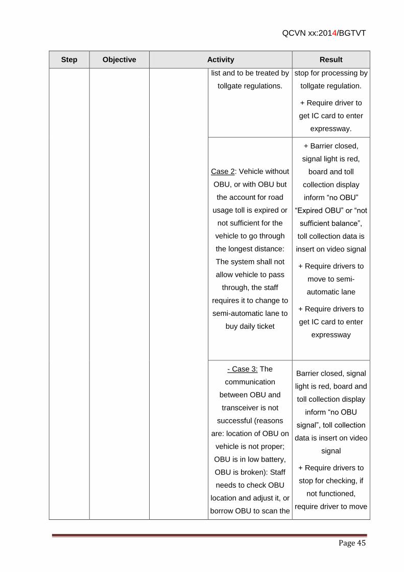
QCVN xx:2014/BGTVT
Page 45
Step Objective Activity Result
list and to be treated by
tollgate regulations.
stop for processing by
tollgate regulation.
+ Require driver to
get IC card to enter
expressway.
Case 2: Vehicle without
OBU, or with OBU but
the account for road
usage toll is expired or
not sufficient for the
vehicle to go through
the longest distance:
The system shall not
allow vehicle to pass
through, the staff
requires it to change to
semi-automatic lane to
buy daily ticket
+ Barrier closed,
signal light is red,
board and toll
collection display
inform “no OBU”
“Expired OBU” or “not
sufficient balance”,
toll collection data is
insert on video signal
+ Require drivers to
move to semi-
automatic lane
+ Require drivers to
get IC card to enter
expressway
- Case 3: The
communication
between OBU and
transceiver is not
successful (reasons
are: location of OBU on
vehicle is not proper;
OBU is in low battery,
OBU is broken): Staff
needs to check OBU
location and adjust it, or
borrow OBU to scan the
Barrier closed, signal
light is red, board and
toll collection display
inform “no OBU
signal”, toll collection
data is insert on video
signal
+ Require drivers to
stop for checking, if
not functioned,
require driver to move
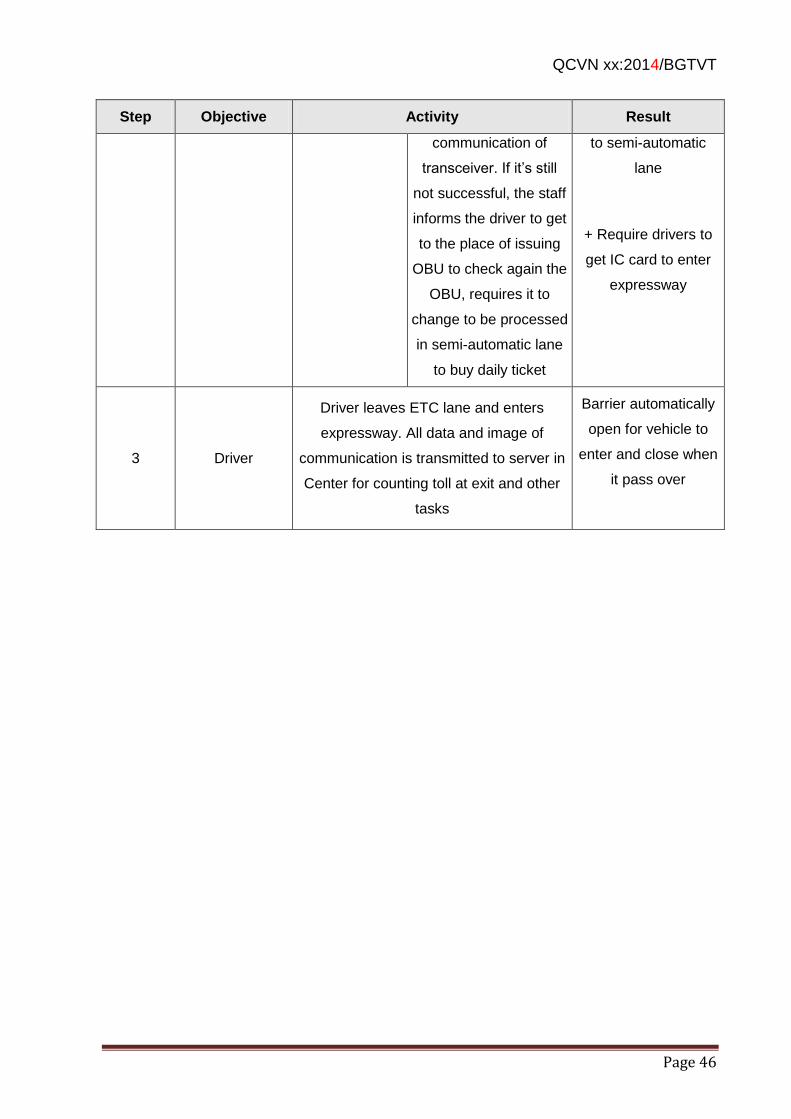
QCVN xx:2014/BGTVT
Page 46
Step Objective Activity Result
communication of
transceiver. If it’s still
not successful, the staff
informs the driver to get
to the place of issuing
OBU to check again the
OBU, requires it to
change to be processed
in semi-automatic lane
to buy daily ticket
to semi-automatic
lane
+ Require drivers to
get IC card to enter
expressway
3 Driver
Driver leaves ETC lane and enters
expressway. All data and image of
communication is transmitted to server in
Center for counting toll at exit and other
tasks
Barrier automatically
open for vehicle to
enter and close when
it pass over
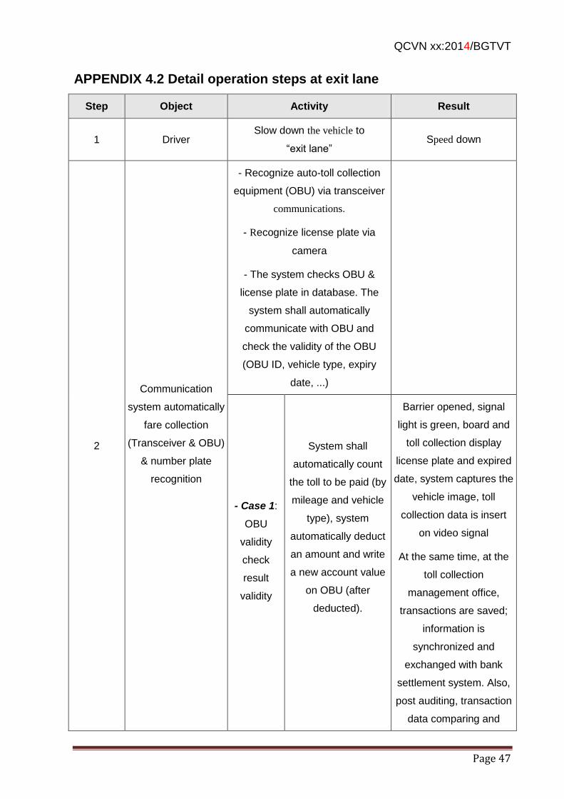
QCVN xx:2014/BGTVT
Page 47
APPENDIX 4.2 Detail operation steps at exit lane
Step Object Activity Result
1 Driver Slow down the vehicle to
“exit lane” Speed down
2
Communication
system automatically
fare collection
(Transceiver & OBU)
& number plate
recognition
- Recognize auto-toll collection
equipment (OBU) via transceiver
communications.
- Recognize license plate via
camera
- The system checks OBU &
license plate in database. The
system shall automatically
communicate with OBU and
check the validity of the OBU
(OBU ID, vehicle type, expiry
date, ...)
- Case 1:
OBU
validity
check
result
validity
System shall
automatically count
the toll to be paid (by
mileage and vehicle
type), system
automatically deduct
an amount and write
a new account value
on OBU (after
deducted).
Barrier opened, signal
light is green, board and
toll collection display
license plate and expired
date, system captures the
vehicle image, toll
collection data is insert
on video signal
At the same time, at the
toll collection
management office,
transactions are saved;
information is
synchronized and
exchanged with bank
settlement system. Also,
post auditing, transaction
data comparing and
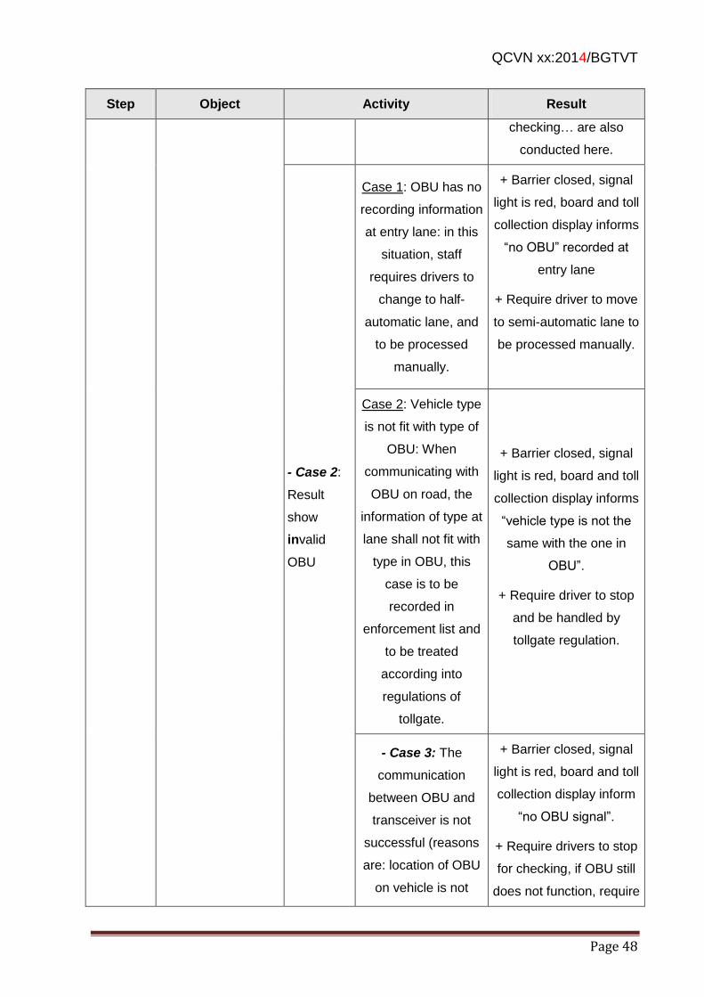
QCVN xx:2014/BGTVT
Page 48
Step Object Activity Result
checking… are also
conducted here.
- Case 2:
Result
show
invalid
OBU
Case 1: OBU has no
recording information
at entry lane: in this
situation, staff
requires drivers to
change to half-
automatic lane, and
to be processed
manually.
+ Barrier closed, signal
light is red, board and toll
collection display informs
“no OBU” recorded at
entry lane
+ Require driver to move
to semi-automatic lane to
be processed manually.
Case 2: Vehicle type
is not fit with type of
OBU: When
communicating with
OBU on road, the
information of type at
lane shall not fit with
type in OBU, this
case is to be
recorded in
enforcement list and
to be treated
according into
regulations of
tollgate.
+ Barrier closed, signal
light is red, board and toll
collection display informs
“vehicle type is not the
same with the one in
OBU”.
+ Require driver to stop
and be handled by
tollgate regulation.
- Case 3: The
communication
between OBU and
transceiver is not
successful (reasons
are: location of OBU
on vehicle is not
+ Barrier closed, signal
light is red, board and toll
collection display inform
“no OBU signal”.
+ Require drivers to stop
for checking, if OBU still
does not function, require
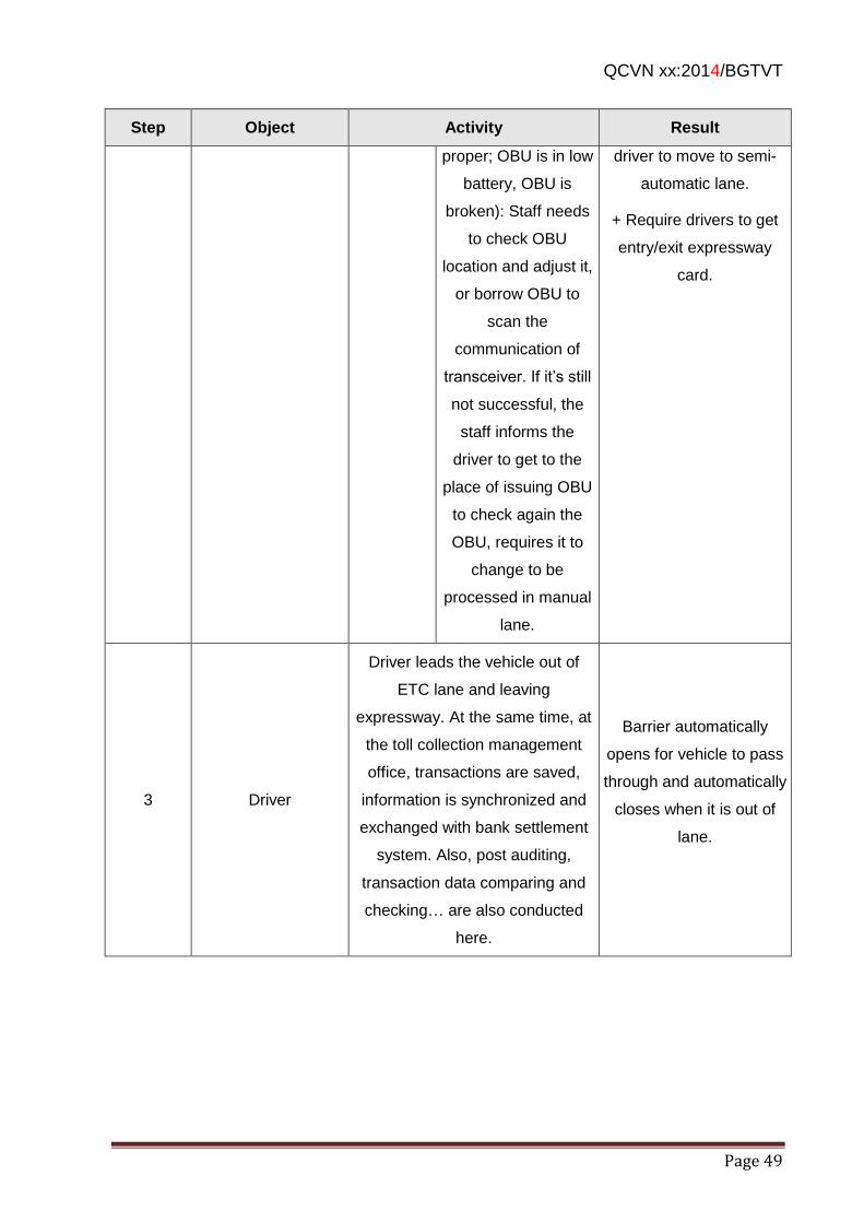
QCVN xx:2014/BGTVT
Page 49
Step Object Activity Result
proper; OBU is in low
battery, OBU is
broken): Staff needs
to check OBU
location and adjust it,
or borrow OBU to
scan the
communication of
transceiver. If it’s still
not successful, the
staff informs the
driver to get to the
place of issuing OBU
to check again the
OBU, requires it to
change to be
processed in manual
lane.
driver to move to semi-
automatic lane.
+ Require drivers to get
entry/exit expressway
card.
3 Driver
Driver leads the vehicle out of
ETC lane and leaving
expressway. At the same time, at
the toll collection management
office, transactions are saved,
information is synchronized and
exchanged with bank settlement
system. Also, post auditing,
transaction data comparing and
checking… are also conducted
here.
Barrier automatically
opens for vehicle to pass
through and automatically
closes when it is out of
lane.
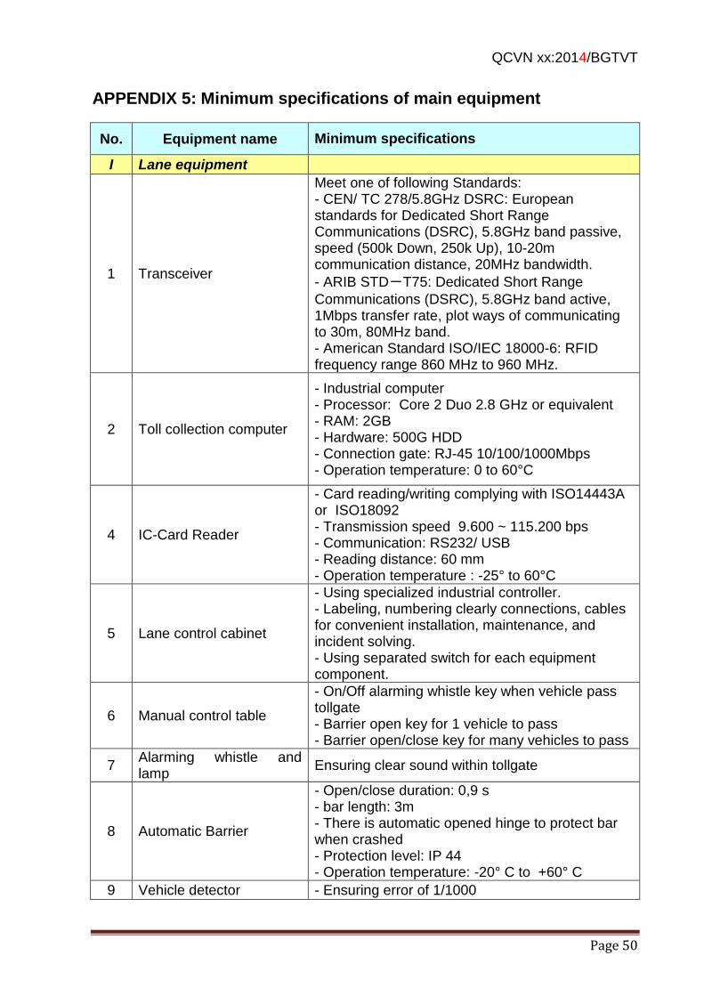
QCVN xx:2014/BGTVT
Page 50
APPENDIX 5: Minimum specifications of main equipment
No. Equipment name Minimum specifications
I Lane equipment
1 Transceiver
Meet one of following Standards: - CEN/ TC 278/5.8GHz DSRC: European standards for Dedicated Short Range Communications (DSRC), 5.8GHz band passive, speed (500k Down, 250k Up), 10-20m communication distance, 20MHz bandwidth.
- ARIB STD-T75: Dedicated Short Range
Communications (DSRC), 5.8GHz band active, 1Mbps transfer rate, plot ways of communicating to 30m, 80MHz band. - American Standard ISO/IEC 18000-6: RFID frequency range 860 MHz to 960 MHz.
2 Toll collection computer
- Industrial computer - Processor: Core 2 Duo 2.8 GHz or equivalent - RAM: 2GB - Hardware: 500G HDD - Connection gate: RJ-45 10/100/1000Mbps - Operation temperature: 0 to 60°C
4 IC-Card Reader
- Card reading/writing complying with ISO14443A or ISO18092 - Transmission speed 9.600 ~ 115.200 bps - Communication: RS232/ USB - Reading distance: 60 mm - Operation temperature : -25° to 60°C
5 Lane control cabinet
- Using specialized industrial controller. - Labeling, numbering clearly connections, cables for convenient installation, maintenance, and incident solving. - Using separated switch for each equipment component.
6 Manual control table
- On/Off alarming whistle key when vehicle pass tollgate - Barrier open key for 1 vehicle to pass - Barrier open/close key for many vehicles to pass
7 Alarming whistle and lamp
Ensuring clear sound within tollgate
8 Automatic Barrier
- Open/close duration: 0,9 s - bar length: 3m - There is automatic opened hinge to protect bar when crashed - Protection level: IP 44 - Operation temperature: -20° C to +60° C
9 Vehicle detector - Ensuring error of 1/1000
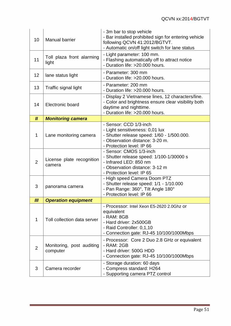
QCVN xx:2014/BGTVT
Page 51
10 Manual barrier
- 3m bar to stop vehicle - Bar installed prohibited sign for entering vehicle following QCVN 41:2012/BGTVT. - Automatic on/off light switch for lane status
11 Toll plaza front alarming light
- Light parameter: 100 mm. - Flashing automatically off to attract notice - Duration life: >20.000 hours.
12 lane status light - Parameter: 300 mm - Duration life: >20.000 hours.
13 Traffic signal light - Parameter: 200 mm - Duration life: >20.000 hours.
14 Electronic board
- Display 2 Vietnamese lines, 12 characters/line. - Color and brightness ensure clear visibility both daytime and nighttime. - Duration life: >20.000 hours.
II Monitoring camera
1 Lane monitoring camera
- Sensor: CCD 1/3-inch - Light sensitiveness: 0,01 lux - Shutter release speed: 1/60 - 1/500.000. - Observation distance: 3-20 m. - Protection level: IP 66
2 License plate recognition camera
- Sensor: CMOS 1/3-inch - Shutter release speed: 1/100-1/30000 s - Infrared LED: 850 nm - Observation distance: 3-12 m - Protection level: IP 65
3 panorama camera
- High speed Camera Doom PTZ - Shutter release speed: 1/1 - 1/10.000 - Pan Range: 360°, Tilt Angle 180° - Protection level: IP 66
III Operation equipment
1 Toll collection data server
- Processor: Intel Xeon E5-2620 2.0Ghz or equivalent - RAM: 8GB - Hard driver: 2x500GB - Raid Controller: 0,1,10 - Connection gate: RJ-45 10/100/1000Mbps
2 Monitoring, post auditing computer
- Processor: Core 2 Duo 2.8 GHz or equivalent - RAM: 2GB - Hard driver: 500G HDD - Connection gate: RJ-45 10/100/1000Mbps
3 Camera recorder - Storage duration: 60 days - Compress standard: H264 - Supporting camera PTZ control
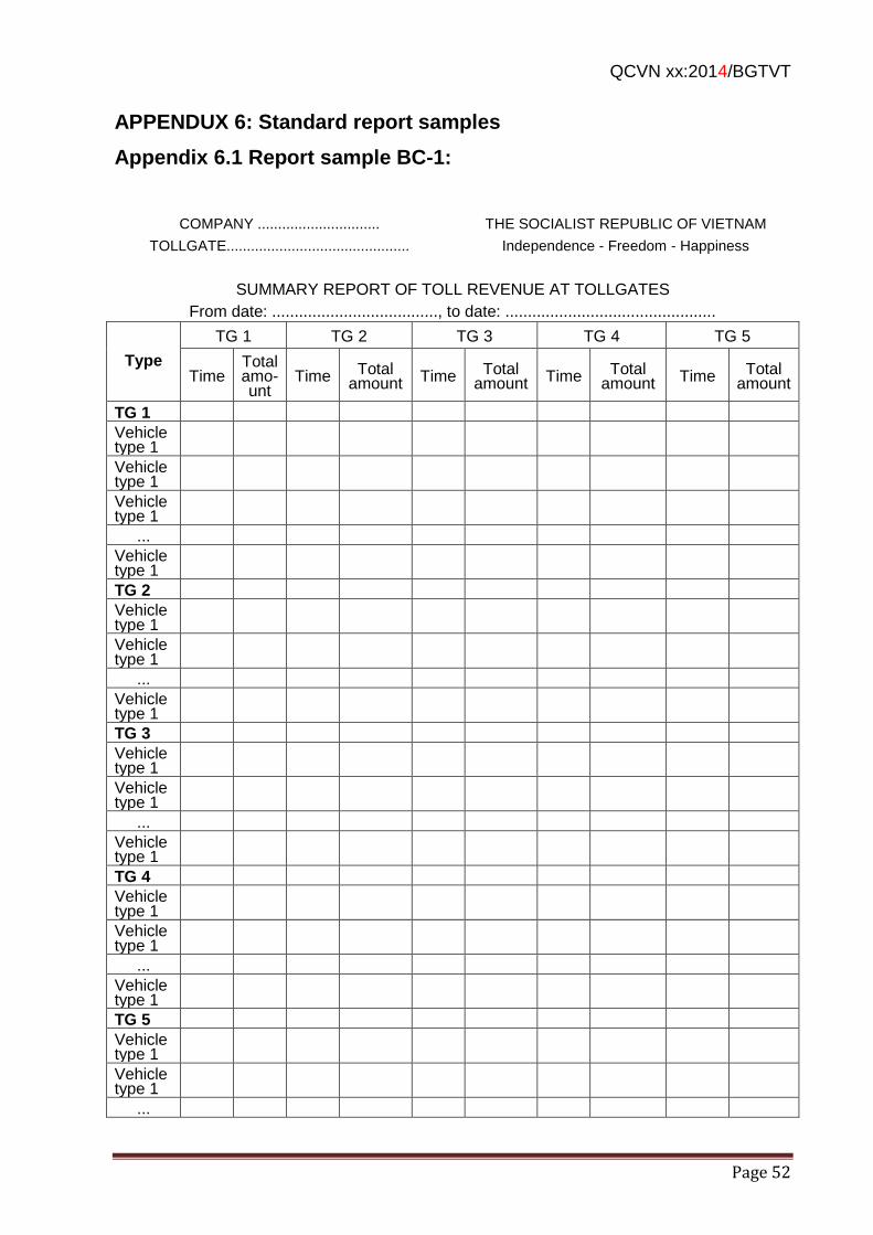
QCVN xx:2014/BGTVT
Page 52
APPENDUX 6: Standard report samples
Appendix 6.1 Report sample BC-1:
COMPANY ..............................
TOLLGATE.............................................
THE SOCIALIST REPUBLIC OF VIETNAM
Independence - Freedom - Happiness
SUMMARY REPORT OF TOLL REVENUE AT TOLLGATES
From date: ....................................., to date: ...............................................
Type
TG 1 TG 2 TG 3 TG 4 TG 5
Time Total amo-unt
Time Total amount Time Total
amount Time Total amount Time Total
amount
TG 1
Vehicle type 1
Vehicle type 1
Vehicle type 1
...
Vehicle type 1
TG 2
Vehicle type 1
Vehicle type 1
...
Vehicle type 1
TG 3
Vehicle type 1
Vehicle type 1
...
Vehicle type 1
TG 4
Vehicle type 1
Vehicle type 1
...
Vehicle type 1
TG 5
Vehicle type 1
Vehicle type 1
...

QCVN xx:2014/BGTVT
Page 53
Vehicle type 1
Total: ...................................... Total amount:........................................ In word:................................
Prepared by (Day).....(month) .....(year)...... Tollgate director
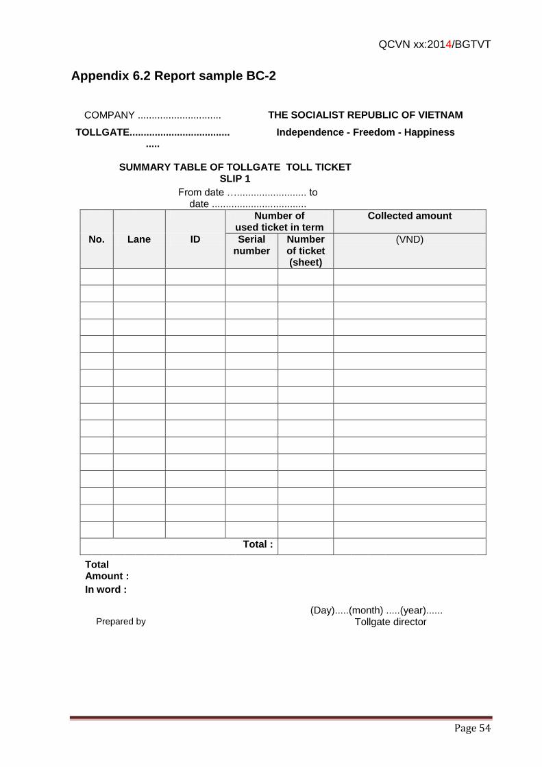
QCVN xx:2014/BGTVT
Page 54
Appendix 6.2 Report sample BC-2
COMPANY ..............................
TOLLGATE.........................................
THE SOCIALIST REPUBLIC OF VIETNAM
Independence - Freedom - Happiness
SUMMARY TABLE OF TOLLGATE TOLL TICKET SLIP 1
From date …......................... to date ..................................
Number of used ticket in term
Collected amount
No. Lane ID Serial number
Number of ticket (sheet)
(VND)
Total :
Total Amount :
In word :
(Day).....(month) .....(year)......
Tollgate director
Prepared by
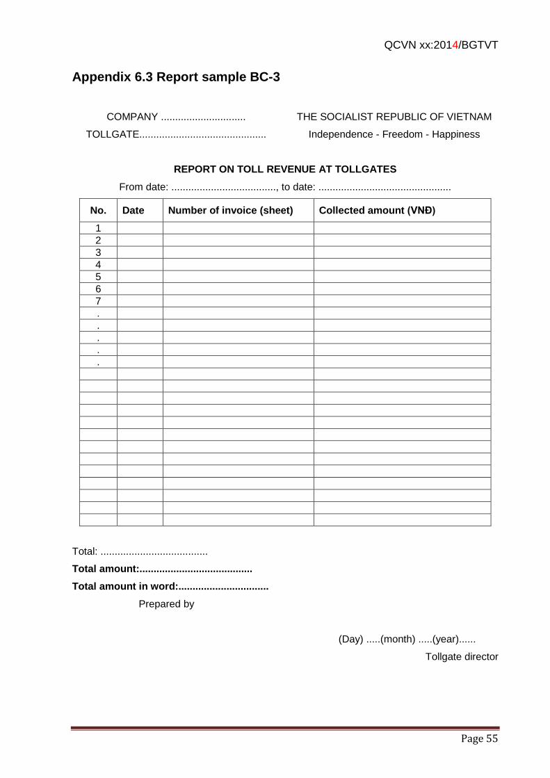
QCVN xx:2014/BGTVT
Page 55
Appendix 6.3 Report sample BC-3
COMPANY ..............................
TOLLGATE.............................................
THE SOCIALIST REPUBLIC OF VIETNAM
Independence - Freedom - Happiness
REPORT ON TOLL REVENUE AT TOLLGATES
From date: ....................................., to date: ...............................................
No. Date Number of invoice (sheet) Collected amount (VNĐ)
1
2
3
4
5
6
7
.
.
.
.
.
Total: ......................................
Total amount:........................................
Total amount in word:................................
Prepared by
(Day) .....(month) .....(year)......
Tollgate director
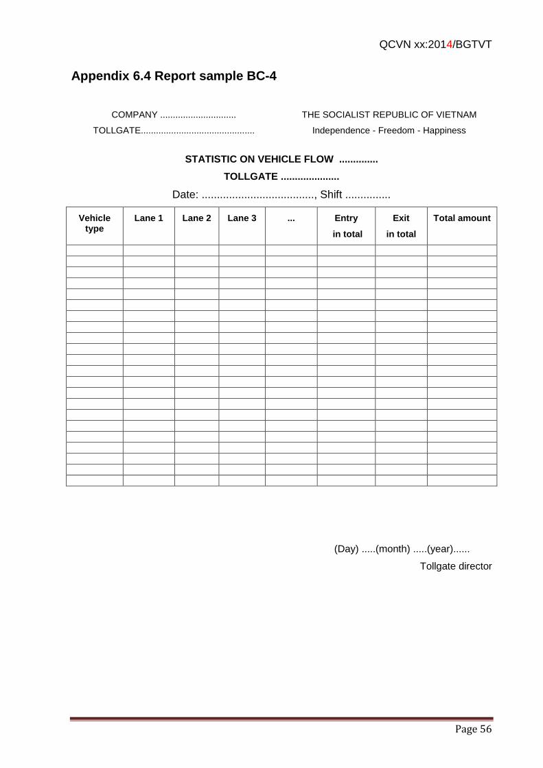
QCVN xx:2014/BGTVT
Page 56
Appendix 6.4 Report sample BC-4
COMPANY ..............................
TOLLGATE.............................................
THE SOCIALIST REPUBLIC OF VIETNAM
Independence - Freedom - Happiness
STATISTIC ON VEHICLE FLOW ..............
TOLLGATE .....................
Date: ....................................., Shift ...............
Vehicle type
Lane 1 Lane 2 Lane 3 ... Entry
in total
Exit
in total
Total amount
(Day) .....(month) .....(year)......
Tollgate director
添付資料-8
DRAFT QCVN OF
MANAGEMENT CENTER/OFFICE FOR EXPRESSWAYS
( SUB-GROUP 8 )
SOCIALIST REPUBLIC OF VIETNAM
QCVN XX : 2014/BGTVT
NATIONAL REGULATION ON TRAFFIC MANAGEMENT CENTER FOR EXPRESSWAYS
Quy chuẩn Kỹ thuật về Trung tâm Quản lý Điều hành Giao thông
Đường cao tốc
HA NOI - 2014
1ST DRAFT
(Sub-Group 8) 2014.03.30
NATIONAL TECHNICAL REGULATION QCVN XX : 2014/BGTVT
2
Foreword
QCVN XX:2014/BGTVT was compiled by the Drafting Department for National Technical
Regulation on Traffic Monitoring and Management System for Expressways (established
under the Decision No. 2252/QĐ-BGTVT on July 31st 2013 of MOT), approved by the
Ministry of Science and Technology, and issued by Ministry of Transportation in
accordance with the Circular No. ....../2014/TT - BGTVT on ......... 2014
NATIONAL TECHNICAL REGULATION QCVN XX : 2014/BGTVT
3
NATIONAL TECHNICAL REGULATION
O HIGHWAY TRAFFIC MANAGEMENT CENTER
Quy chuẩn Kỹ thuật Quốc gia về Trung tâm Quản lý Điều hành Giao thông Đường cao tốc
1 GENERAL REGULATION .............................................................................................. 5
1.1 Scope ..................................................................................................................... 5
1.2 Application Object ................................................................................................... 5
1.3 Reference Materials ................................................................................................ 5
1.4 Terminology and Definition ..................................................................................... 5
1.5 Abbreviations .......................................................................................................... 6
2 TECHNICAL REGULATION........................................................................................... 6
2.1 Road Management Offices ..................................................................................... 6
2.1.1 Performance of Functions ................................................................................ 6
2.1.2 Technical Infrastructure System ....................................................................... 7
2.2 Regional Main Center ............................................................................................. 8
2.2.1 Performance of Functions ................................................................................ 8
2.2.2 Technical Infrastructure System ....................................................................... 9
2.3 Requirements on Design and Development for Equipment at Traffic Management
centers .............................................................................................................................. 9
2.3.1 Design Scope .................................................................................................. 9
2.3.2 Equipment Room ............................................................................................. 9
2.3.3 Traffic Operation Room .................................................................................. 10
2.3.4 Telephone System ......................................................................................... 11
2.3.5 Data Transmission Network ........................................................................... 12
2.3.6 Supporting Device Systems ........................................................................... 13
2.4 Exchanged Information and Data among Traffic Managment Centers .................. 14
2.4.1 Exchange of Traffic Image Data ..................................................................... 14
2.4.2 Exchange of Vehicle Detection Data .............................................................. 15
2.4.3 Exchange of Weather Data ............................................................................ 15
2.4.4 Exchange of Vehicle License Plate Data ........................................................ 16
2.4.5 Exchange of Traffic Event Information ........................................................... 16
NATIONAL TECHNICAL REGULATION QCVN XX : 2014/BGTVT
4
2.4.6 Exchange of Indication Information and Traffic Control .................................. 17
2.4.7 Exchange of Toll Collection Information ......................................................... 17
2.4.8 Communication Standards among Centers .................................................... 18
2.5 Requirements on Management Software .............................................................. 18
2.5.1 Management Software at Road Management Offices .................................... 18
2.5.2 Management Software at Regional Main Center ............................................ 19
2.5.3 Software for Providing Traffic Information through Internet ............................ 19
3 REGULATION ON MANAGEMENT ............................................................................. 19
4 IMPLEMENTING ORGANIZATIONS ........................................................................... 20
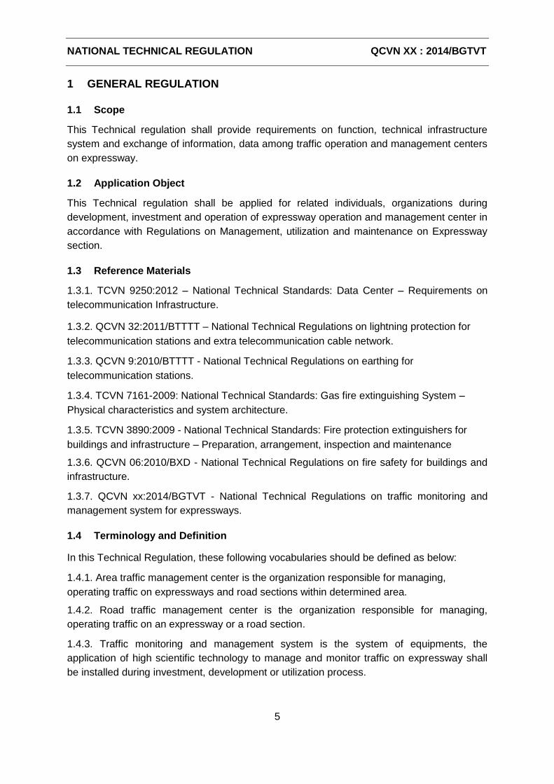
NATIONAL TECHNICAL REGULATION QCVN XX : 2014/BGTVT
5
1 GENERAL REGULATION
1.1 Scope
This Technical regulation shall provide requirements on function, technical infrastructure
system and exchange of information, data among traffic operation and management centers
on expressway.
1.2 Application Object
This Technical regulation shall be applied for related individuals, organizations during
development, investment and operation of expressway operation and management center in
accordance with Regulations on Management, utilization and maintenance on Expressway
section.
1.3 Reference Materials
1.3.1. TCVN 9250:2012 – National Technical Standards: Data Center – Requirements on
telecommunication Infrastructure.
1.3.2. QCVN 32:2011/BTTTT – National Technical Regulations on lightning protection for
telecommunication stations and extra telecommunication cable network.
1.3.3. QCVN 9:2010/BTTTT - National Technical Regulations on earthing for
telecommunication stations.
1.3.4. TCVN 7161-2009: National Technical Standards: Gas fire extinguishing System –
Physical characteristics and system architecture.
1.3.5. TCVN 3890:2009 - National Technical Standards: Fire protection extinguishers for
buildings and infrastructure – Preparation, arrangement, inspection and maintenance
1.3.6. QCVN 06:2010/BXD - National Technical Regulations on fire safety for buildings and
infrastructure.
1.3.7. QCVN xx:2014/BGTVT - National Technical Regulations on traffic monitoring and
management system for expressways.
1.4 Terminology and Definition
In this Technical Regulation, these following vocabularies should be defined as below:
1.4.1. Area traffic management center is the organization responsible for managing,
operating traffic on expressways and road sections within determined area.
1.4.2. Road traffic management center is the organization responsible for managing,
operating traffic on an expressway or a road section.
1.4.3. Traffic monitoring and management system is the system of equipments, the
application of high scientific technology to manage and monitor traffic on expressway shall
be installed during investment, development or utilization process.
NATIONAL TECHNICAL REGULATION QCVN XX : 2014/BGTVT
6
1.4.4. Traffic images data is the data of video images from cameras installed on roadside
to monitor expressway traffic condition.
1.4.5. Vehicle detection data is the data of vehicle volume, velocity from vehicle
detectors installed on expressway.
1.4.6. Weather data is the data of temperature, rainfall, vision, wind velocity from weather
sensors installed on expressway.
1.4.7. Vehicle license plate code data is the data of recognizing license plate,
supervising vehicle flows which are automatically processed in images from cameras on
expressway.
1.4.8. Traffic event information describes accidents, incidents and provides notification
on securing traffic safety on expressway.
1.4.9. Traffic indication is changeable information which is displayed on electronic traffic
signs on expressway.
1.4.10. Traffic control information is regulation on speed limitation on lanes and shall be
remotely controlled through electronic signs on expressway.
1.4.11. Toll collection information is the integrated information of toll collection which is
applied for vehicles accessing to expressway section.
1.4.12. Data queries requirement is the form of exchanging data which sender shall
respond the data receiver requires (Pull mechanism).
1.4.13. Data receiving registration: is the form of exchanging data in cycle or in case of new
data arising from sender to register (Push mechanism).
1.5 Abbreviations
TM Traffic Management
PSTN Public Switchboard Telephone Network
VLAN Virtual Local Area Network – mạng nội bộ ảo
2 TECHNICAL REGULATION
2.1 Road Management Offices
2.1.1 Performance of Functions
The investors or operating and maintaining organization should develope and manage
Road Management Offices in order to surveil, control and secure traffic safety on
expressway within jurisdiction. The office shall be responsible for operating Traffic
Monitoring and Management System for Expressway to implement these below tasks:
NATIONAL TECHNICAL REGULATION QCVN XX : 2014/BGTVT
7
a. Collecting and processing all types of traffic information on expressways including
camera images, vehicle detection data, roadside weather, recognition alert on
accidents, incidents and traffic violations of drivers.
b. Monitoring and managing information on related events occurred on expressway,
resulted in traffic congestion, accident, incident, dangerous weather and planned
events such as work site, special holiday.
c. Providing changeable indications by time such as weather condition, traffic
crowdedness, travelling consultation, planned travelling time, notification on incidents,
accidents, work site and information related to traffic on expressway.
d. Receiving and timely processing information on accident, broken vehicle, work site
on expressway which shall be notified to Office from different sources (automatic
information collection system; patrol crew, security patrol on expressway; residence
and road users) to assign patrol crew, respond traffic condition and to report the
police, the rescue teams and concerned forces so that they urgenty arrive at the site
and function the tasks as regulation..
e. Proactively performing measures to regulate traffic remotely in order to secure traffic
safety such as adjusting lanes or restricting vehicle velocity on expressway in
accordance with actual traffic condition.
f. Gathering information on toll collection and heavy truck control (if any) on
expressway to monitor on expressway.
g. Connecting and fully transmitting traffic information, data to Area TMO Center to
control and operate in accordance with regulations of Article 2.4 in this Technical
Regulation.
h. Receiving and providing information, managing the implementation of special traffic
organizing methods under the direct guidance of Area TMO Center in case of
unexpected difficult situation.
i. Monitoring the performance and maintaining equipments in traffic monitor
management system on expressways.
2.1.2 Technical Infrastructure System
Road Management Offices on Expressway shall be equipped with technical
infrastructure system including following primary components:
a. Operation room at office shall consist of Equipment Room, Traffic Operation Room
and Working Room for organizational mechanism at Road Management Offices.
b. Equipments at office shall consist of servers of sub-systems of traffic monitoring and
management system for expressways as regulated in QCVN xx:2014/BGTVT –
National technical regulation on traffic monitoring and management system for
expressways.
c. Station computers and displaying screens shall be used for traffic monitoring and
management for expressways.
NATIONAL TECHNICAL REGULATION QCVN XX : 2014/BGTVT
8
d. Communication system shall receive emergency calls, to connect information with
higher authorities, functional forces who cotntribute to secure traffic safety and
handle accidents, incidents on expressway in accordance with regulations.
e. Transmission network system shall connect information between Offices and
roadside equipments in road traffic monitor management system, and shall secure
data connection with Regional Main Center.
f. Necessary equipments and devices (purchasing or borrowing) shall be used in
periodical maintenance for roadside equipments in traffic monitor management
system.
Technical infrastructure system shall be developed at Road Management Offices, based
on design scale, the system should be utilized to operate and manage in one or many
different expressway sections.
2.2 Regional Main Center
2.2.1 Performance of Functions
Regional Main Center is the primary unit of Expressway Management Organization
whose responsibility for monitoring, controlling the performance of Road Management
Offices and controlling area traffic condition within jurisdiction. Regional Main Center shall
function these following tasks:
a. Gathering and managing traffic information which are transmitted from Road
Management Offices to Regional Main Center with the aim to monitor, manage and
secure highway traffic safety within jurisdiction.
b. Directly assigning the operation and maintenance organization of expressway section
in area to solve serious accidents and incidents. Supervising the information provided
from Road Management Offices during rescuing procedure.
c. Coordinating traffic of area highway system by special traffic organizing methods
under the approval of competent authorities in case of emergency situations, natural
disasters or national security.
d. Disseminating information to Road Management Offices so as to regulate and avoid
traffic congestion among sections within the area.
e. Implementing highway security patrol so as to check, monitor and surveil the patrol
task on expressway; process or cooperate to process violations in accordance with
regulations on expressway management.
f. Providing consultation on travelling route and traffic condition of sections in an area
to road users.
g. Managing and storing data related to highway traffic within the area where is in use
to serve plan managing, development and utilization planning for expressway by
Expressway Management Office.
h. .
NATIONAL TECHNICAL REGULATION QCVN XX : 2014/BGTVT
9
2.2.2 Technical Infrastructure System
Regional Main Center shall be operated with requirement of securing technical
infrastructure system included these below major components:
a. Head office shall be prepared with equipment room, area traffic operation room and
other working rooms in accordance with structure, function and managing
responsibility of Regional Main Center.
b. All servers, computers and large-size displays shall secure the performance of traffic
monitor management system at Regional Main Center.
c. Communication system shall be used to indicate and operate the performance of
Road Management Offices, the operating and maintaining organizations, and to
cooperate with other functional organizations.
d. Transmission network system shall secure connection and exchange of traffic
information, data among Road Management Offices within jurisdiction.
e. Other necessary tools and equipments shall be used for security patrol on
expressway sections.
The location of Regional Main Center shall be appropriate and convenient for security
patrol on expressway sections within jurisdiction. It is preferred to select the locations which
are prepared with communication infrastructures by telecommunication carriers so as to
easily implement communication system and high-speed Data Transmission Network for
Center.
2.3 Requirements on Design and Development for Equipment at Traffic Management
centers
2.3.1 Design Scope
Requirements on design shall be applied for both Road Management Offices and
Regional Main Center. Design Scope for Traffic Management Centers shall be required to
achieve that level 2 of Data Integration Center in accordance with National Standards TCVN
9250:2012 and be approved by competent authorities of investing.
The design scale shall be secured to arrange some areas such as center building,
parking area, area for the backup generator.
The building design shall separate the area of Equipment Room and Traffic Operation
Room with other areas such as reception area, working room, meeting room, hall, etc.
2.3.2 Equipment Room
Equipment room shall be designed according to Standards for Machine Room at Data
Integration Center. This room shall have adequate utilities for equipment arrangement as
below:
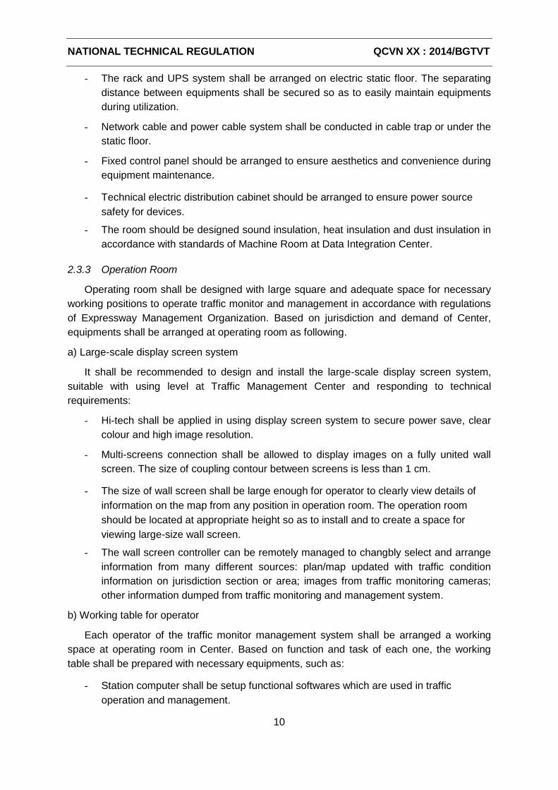
NATIONAL TECHNICAL REGULATION QCVN XX : 2014/BGTVT
10
- The rack and UPS system shall be arranged on electric static floor. The separating
distance between equipments shall be secured so as to easily maintain equipments
during utilization.
- Network cable and power cable system shall be conducted in cable trap or under the
static floor.
- Fixed control panel should be arranged to ensure aesthetics and convenience during
equipment maintenance.
- Technical electric distribution cabinet should be arranged to ensure power source
safety for devices.
- The room should be designed sound insulation, heat insulation and dust insulation in
accordance with standards of Machine Room at Data Integration Center.
2.3.3 Operation Room
Operating room shall be designed with large square and adequate space for necessary
working positions to operate traffic monitor and management in accordance with regulations
of Expressway Management Organization. Based on jurisdiction and demand of Center,
equipments shall be arranged at operating room as following.
a) Large-scale display screen system
It shall be recommended to design and install the large-scale display screen system,
suitable with using level at Traffic Management Center and responding to technical
requirements:
- Hi-tech shall be applied in using display screen system to secure power save, clear
colour and high image resolution.
- Multi-screens connection shall be allowed to display images on a fully united wall
screen. The size of coupling contour between screens is less than 1 cm.
- The size of wall screen shall be large enough for operator to clearly view details of
information on the map from any position in operation room. The operation room
should be located at appropriate height so as to install and to create a space for
viewing large-size wall screen.
- The wall screen controller can be remotely managed to changbly select and arrange
information from many different sources: plan/map updated with traffic condition
information on jurisdiction section or area; images from traffic monitoring cameras;
other information dumped from traffic monitoring and management system.
b) Working table for operator
Each operator of the traffic monitor management system shall be arranged a working
space at operating room in Center. Based on function and task of each one, the working
table shall be prepared with necessary equipments, such as:
- Station computer shall be setup functional softwares which are used in traffic
operation and management.
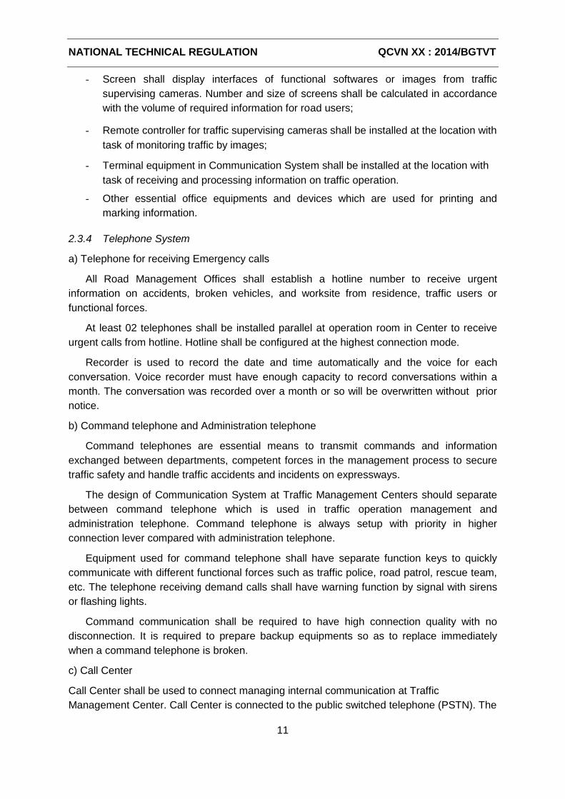
NATIONAL TECHNICAL REGULATION QCVN XX : 2014/BGTVT
11
- Screen shall display interfaces of functional softwares or images from traffic
supervising cameras. Number and size of screens shall be calculated in accordance
with the volume of required information for road users;
- Remote controller for traffic supervising cameras shall be installed at the location with
task of monitoring traffic by images;
- Terminal equipment in Communication System shall be installed at the location with
task of receiving and processing information on traffic operation.
- Other essential office equipments and devices which are used for printing and
marking information.
2.3.4 Telephone System
a) Telephone for receiving Emergency calls
All Road Management Offices shall establish a hotline number to receive urgent
information on accidents, broken vehicles, and worksite from residence, traffic users or
functional forces.
At least 02 telephones shall be installed parallel at operation room in Center to receive
urgent calls from hotline. Hotline shall be configured at the highest connection mode.
Recorder is used to record the date and time automatically and the voice for each
conversation. Voice recorder must have enough capacity to record conversations within a
month. The conversation was recorded over a month or so will be overwritten without prior
notice.
b) Command telephone and Administration telephone
Command telephones are essential means to transmit commands and information
exchanged between departments, competent forces in the management process to secure
traffic safety and handle traffic accidents and incidents on expressways.
The design of Communication System at Traffic Management Centers should separate
between command telephone which is used in traffic operation management and
administration telephone. Command telephone is always setup with priority in higher
connection lever compared with administration telephone.
Equipment used for command telephone shall have separate function keys to quickly
communicate with different functional forces such as traffic police, road patrol, rescue team,
etc. The telephone receiving demand calls shall have warning function by signal with sirens
or flashing lights.
Command communication shall be required to have high connection quality with no
disconnection. It is required to prepare backup equipments so as to replace immediately
when a command telephone is broken.
c) Call Center
Call Center shall be used to connect managing internal communication at Traffic
Management Center. Call Center is connected to the public switched telephone (PSTN). The
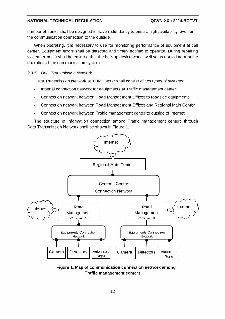
NATIONAL TECHNICAL REGULATION QCVN XX : 2014/BGTVT
12
number of trunks shall be designed to have redundancy to ensure high availability level for
the communication connection to the outside.
When operating, it is necessary to use for monitoring performance of equipment at call
center. Equipment errors shall be detected and timely notified to operator. During repairing
system errors, it shall be ensured that the backup device works well so as not to interrupt the
operation of the communication system..
2.3.5 Data Transmission Network
Data Transmission Network at TOM Center shall consist of two types of systems:
- Internal connection network for equipments at Traffic management center
- Connection network between Road Management Offices to roadside equipments
- Connection network between Road Management Offices and Regional Main Center
- Connection network between Traffic management center to outside of Internet
The structure of information connection among Traffic management centers through
Data Transmission Network shall be shown in Figure 1.
Figure 1. Map of communication connection network among
Traffic management centers
Regional Main Center
Road
Management
Offices B
Road
Management
Offices A
Equipments Connection Network
Internet
Internet
Internet
Equipments Connection Network
Center – Center
Connection Network
Camera Detectors Automated
Signs Camera Detectors
Automated
Signs
NATIONAL TECHNICAL REGULATION QCVN XX : 2014/BGTVT
13
The design for Data Transmission Network shall comply with digital transmission system
in National Technical Regulation on Traffic monitoring and management system.
VLAN partitions shall be set up to separate the transmission network types and different
groups of devices in the network.
Firewall device system shall be used to ensure network security for the connection out of
Internet.
2.3.6 Supporting Device Systems
a) Backup engine generator
Traffic Management centers shall be equipped with backup engine generator which is
stably connected to the power network at station and automatically start right after electricity
loss. Time for starting, closing circuit and generating shall last only 02 minutes right after
electricity loss. The engine capacity must be calculated in accordance with the additional
charge for system of main equipments and other necessary devices at Center. The
generator should be kept in good condition with redundant fuel amount for at least
continuously 6-hour operation.
b) UPS device
UPS device shall be used to continuously supply power to system of main equipments
with the aim of securing stable operation in case of electricity loss. The performance and
capacity should be calculated to keep supplying to all equipment for at least 10 minutes.
c) Cooling device
The equipment room should be equipped with cooling system so as to keep performance
environment at approximately 20-250C, moisture at 40-45%, highest congealing point at
210C, largest variation velocity at 50C per hour and functioning 24 hours a day, 365 days a
year.
The cooling device at other working room shall have adequate capacity to remain the
inner temperature at 270C and moisture at 50%..
d) Security Equipment
Traffic Management centers shall be designed with security lock system in Equipment
Room and Traffic Operation Room. Security cameras should be installed to control tracking,
recording activities and persons accessing the operating room and at the entrance to the
center .
e) Fire Protection Extinguishers
Fire protection System of Traffic Management centers shall meet the regulations in
QCVN 06:2010/BXD and TCVN 3890:2009
It is encouraged to prepare automatic fire bell and gas fire extinguisher complying with
National Regulation TCVN 7161-2009 for equipment room in Traffic Management centers in
order to keep computer system in safety if any inciden.
NATIONAL TECHNICAL REGULATION QCVN XX : 2014/BGTVT
14
f) Grounding and Lightning Protection
In accordance with regulations in QCVN 9:2010/BTTTT and QCVN 32:2011/BTTTT.
2.4 Exchanged Information and Data among Traffic Managment Centers
2.4.1 Exchange of Traffic Image Data
Image data from highway monitoring camera system shall be shared among Road
Management Offices shared in Regional Main Center with the aims of:
- Testing, confirming and reporting on condition of traffic congestion, incident
occurrence on highway sections;
- Cooperating to handle and monitor serious accidents, incidents on route within
jurisdiction by images;
- Providing to public visual image of highway traffic monitor on Traffic Information
Website of the Center.
Regional Main Center can require item data of traffic monitoring cameras managed by
Road TOM Centers. The responding data shall consist of camera code, installed location
(section, direction, travelling route), attached with information on technical features such as
PTZ control capability, image data identification, and maximum image resolution.
Regional Main Center can login to receive periodical notification on being time
connection condition and performance error (if any) of monitoring cameras.
Regional Main Center can require pursuing the latest image data from one traffic
monitoring camera. Captured images from Road Management Offices shall be formed in
accordance with common archived standards such as JPEG or PNG.
Regional Main Center Center can require pursuing the data of live video from traffic
monitoring cameras. When receiving requirement, Road Management Offices shall compile
video in accordance with HTTP/MJPEG or RTSP/H246 standard to transmit to Regional
Main Center through Data Transmission Network.
Regional Main Center can require remotely controlling cameras under Road
Management Offices in order to change the view angle or other specifications. The process
of remotely camera control shall follow these below basic steps:
- Regional Main Center shall send camera control requests in which consists of
minimal information on code and changed specifications such as position of PTZ
view angle, focal length, aperture of the camera;
- Road Management shall receive camera control requests and determine which one
should be implemented immediately, which one should be waiting or be rejected
based on priority decentralization level which has been set up in the system;
- Regional Main Center shall be capable of checking result of implementing camera
control requests or cancelling if any request undone.
NATIONAL TECHNICAL REGULATION QCVN XX : 2014/BGTVT
15
2.4.2 Exchange of Vehicle Detection Data
Data on traffic volume which Road Management Offices collect from vehicle sensors
shall be reported to Area TOM Center with the aims of:
- Automatically monitoring, analyzing and evaluating traffic congestion on sections of
highway network;
- Making statistic and defining congestion-prone points in order to operate and
manage highway system effectively;
- Making assess on the effect of traffic monitor management system in securing traffic
safety and processing accidents, incidents;
- Generating data on actual vehicle volume on route which shall be used to develop
propriate traffic management policies.
Regional Main Center shall be capable of requiring data on location list of vehicle
detectors managed by Road Management Offices. Responding data shall consist of
information on code, location (section, direction, and travelling route) of vehicle detecting
points.
Regional Main Center shall be capable of requiring or logining to receive period vehicle
counting data included vehicle detecting point code; beginning time and ending time; the
number of vehicle by lanes, by small size vehicle (length ≤ 6m), large size vehicle (length ≤
12m) ad extra-large size vehicle (length > 12m); vehicle speed shall be averaged for each
lane.
Regional Main Center shall be capable of requiring data on operating history of each
vehicle detector such as installation time, adjusting time, normally active or inactive period.
2.4.3 Exchange of Weather Data
Weather data which Road Management Offices collect from sensor stations on roadside
shall be transmitted to Area TOM Center with the aims of using:
- Notifying extremely dangerous weather condition, therefore Regional Main Center
shall be required to direct and implement special traffic alternatives;
- Providing the weather information on expressway to public on traffic information
Website of Center.
Regional Main Center shall be capable of requiring data on location list of weather
sensors managed by Road Management Offices. Responding data shall consist of
information on code, location (section, direction, and travelling route) of observing points.
Regional Main Center shall be capable of requiring searching or login to receive period
weather notification collected from observing points included information on: observing point
code, beginning time and ending time of measuring period; average, minimum and
maximum temperature; average, minimum and maximum rainfall.
Regional Main Center shall be capable of requiring data on operating history of each
vehicle detector such as installation time, adjusting time, normally active or inactive period.
NATIONAL TECHNICAL REGULATION QCVN XX : 2014/BGTVT
16
2.4.4 Exchange of Vehicle License Plate Data
Vehicle license plate monitoring and identifying cameras could be installed in traffic
monitor management system on route. Data on collect from monitoring cameras shall be
transmitted to thập từ các camera giám sát được truyền về Regional Main Center , in order
to be used for travelling surveillance of which objects pass by checkpoints on highway, and
for the purposes of security and defense.
Regional Main Center shall be capable of requiring data on location list of license plate
monitoring and identifying cameras managed by Road Management Offices. Responding
data shall consist of information on code, location (section, direction, and travelling route) of
the cameras.
Regional Main Center shall be capable of requiring or logining to receive latest data on
vehicle license plate code included information on: monitoring camera code; license plate
and time of idenfying vehicle; measured values of speed, axle load, violation of traffic
regulation (if any); panoramic images and plate number of vehicles.
Regional Main Center shall be capable of requiring data on operating history of each
monitoring camera such as installation time, adjusting time, normally active or inactive period.
2.4.5 Exchange of Traffic Event Information
Information of all events occurred on expressway shall be managed, supervised at Road
Management Offices and be reported to Regional Main Center with the aims of using:
- Timely noticing information on existing accidents, incidents and traffic congestion
condition in order to cooperate with functional forces to secure highway traffic safety;
- Automatically generating statistics about the work of ensuring traffic safety on
highways within jurisdiction
- Providing traffic event information to public through private information channels in
Center such as Internet.
Regional Main Center shall be capable of requiring or logining to receive notification on
newly established events or to update information at Road Management Offices. Event
discription included: event code, time, location (section, direction, and travelling route) of
event site; classification and reason description; serious level, result of clearance and Event
information shall be automatically collected, managed, updated and processed to eliminate
duplication in the system at Regional Main Center.
NATIONAL TECHNICAL REGULATION QCVN XX : 2014/BGTVT
17
2.4.6 Exchange of Indication Information and Traffic Control
Traffic indication and control information which Road Management Offices display on
automated signs shall be transmitted to Regional Main Center with the aims of using:
- Monitoring the changeable information provision and traffic control which Road
Management Offices shall be responsible to execute in accordance with regulations;
- Indicating Road Management Offices to provide special information or to adjust lane
speed in unexpectedly difficult situations;
- Providing indications and traffic control information to public through traffic
information Website in Center.
Regional Main Center shall be capable of requiring data on list of installed electronic
traffic signs (including information signs and speed limitation) which shall be managed by the
Road Management Offices. Responding data must contain information on number and
installation location (route, direction, project management, lanes) of electronic traffic signs
attached to the parameters of size and maximum length of the message being displayed on
the signs.
Regional Main Center shall be capable of requiring data or logining to receive
information about subscription information updated instructions on the electronic traffic signs.
All messages contain the following information: number of electronic signs, time status
updates and operation of the device, the content of instruction, traffic control being displayed
on electronic signs.
Regional Main Center shall be capable of requiring data or login to receive notification on
indications which shall be updated on automated traffic signs. The requirement procedure of
disclosing indications and remotely traffic controlling shall follow these basic steps:
- Regional Main Center shall send requirement including indications and control
information attached with sign code and validity of information;
- Road Management Offices shall receive and determine which one should be
implemented immediately, which one should be waiting or be rejected based on
priority decentralization level which has been set up in the system;
- Regional Main Center shall be capable of checking result of implementing camera
control requests or cancelling if any request undone.
2.4.7 Exchange of Toll Collection Information
Toll collection information managed and monitored at Road Management Offices shall
be reported to Regional Main Center with the aim of generating data for management in
accordance with regulation. Information on rate of fee and collection methods on sections
shall be disclosed on the traffic information Website of Regional Main Center.
Regional Main Center shall be capable of requiring or logining to receive daily notification
on toll collection report included: section, collecting time; the number of vehicle and the
amount of fee by tariff, vehicle classification; the number of vehicle using automatic
collection method.
NATIONAL TECHNICAL REGULATION QCVN XX : 2014/BGTVT
18
2.4.8 Communication Standards among Centers
Communication standards shall be unified in exchange of information, data between
Regional Main Center and Road Management Offices. Equipments and softwares in traffic
monitor management systems on expressways shall be willing to connect in accordance with
general communication standards.
Communication standards shall be developed on the basic of communication rules
between Center-Center which is applied in Intelligent Transportation Systems. The
standards shall be required to secure compliance with the transmission network based on
Ethernet protocol which is established among Traffic Management Centers.
2.5 Requirements on Management Software
2.5.1 Management Software at Road Management Offices
At Road Management Offices, the management software shall create interface for user
to do the following tasks:
- Manage, monitor image, PTZ control, set the record mode, search and view photos
of the CCTV traffic;
- - Subscribe online charts, statistics about traffic flow collected from parking lots
located on the highway;
- - To monitor and handle the alerts generated by the system detects events analyzed
by automated image;
- Set up and manage public information through electronic traffic signs on highway
signs include instruction information, speed limit signs are changed and other
information provision systems;
- Manage the setup and removal of traffic events taking place on the highway includes
the group of incidents (accidents, vehicle damage incidents, road incidents, lost /
damaged equipment, natural/ disaster graphics), the offense of traffic safety rules,
the location of traffic jams, dangerous weather, roadworks, the traffic restrictions
(closed roads, vehicle speed limit) and other special events;
- Manage, monitor traffic flow in and out at the toll booths, aggregating collected fees
from time to time and post-inspection of the image turn charge;
- Monitor and handle the information on overload, oversized vehicle confirmed by
checking the system load vehicles.
NATIONAL TECHNICAL REGULATION QCVN XX : 2014/BGTVT
19
2.5.2 Management Software at Regional Main Center
At Regional Main Center, the management software shall create interface for user to do
the following tasks:
- Supervise CCTV images of traffic were selected points in the region;
- Monitor traffic, the traffic situation on the area map, receive information about the
accidents and incidents occurred on the highway;
- Test and certification data reports from the Road Management Offices through a
system of information technology applications;
- Manage the provision of information and traffic operation to Road Traffic
Management Offices;
- General information, reporting periodically operated exploit the situation to ensure
safe transportation highways within the region;
- Manage the storage of various kinds of traffic data for using in planning and
development.
2.5.3 Software for providing traffic information through Internet
Regional Main Center shall be responsible for managing and operating Website to
provide to public about traffic information services within the region, including:
- Traffic information map which identifies the location congestion, accidents, incidents,
construction, or traffic restrictions;
- Consultion for the road user about expected travelling time, and transportation fees;
- The important guidance information is published via electronic traffic signs on the
highway;
- Images taken from CCTV traffic monitoring on expressways.
3 REGULATION ON MANAGEMENT
3.1 Road Management Offices shall be organized, operated and managed on all highway
sections and roads during utilization.
3.2 Expressway Management Agency under Ministry of Transportation shall be responsible
for arranging, investing, developing and operating Regional Main Center as plan.
3.3 The connection between Road Management Offices shall Regional Main Center Center
shall follow the procedure and direction of Expressway Management Organization.
NATIONAL TECHNICAL REGULATION QCVN XX : 2014/BGTVT
20
4 IMPLEMENTING ORGANIZATIONS
4.1 The organizations and individuals realated to the planning, development, investment,
construction, management and operation of executive management highway traffic center
must comply with the provisions of this technical Regulation and relevant legal documents..
4.2 In case of technical regulations, standards, technical documents cited in this Technical
Regulation have been changed; supplement or replacement shall comply with the provisions
in the new text.
4.3 Directorate of Road in Vietnam shall be in charge of establishing regulations on
management and inspecting the work of organization, operation and management at
Highway Traffic Management Center.
4.4 Directorate of Road in Vietnam shall take responsibility and cooperate with Department
of Science and Technology (Ministry of Transportation) and other competent agencies to
guide, execute and implement this Technical Regulation./.
添付資料-9
QCVN SCHEDULE
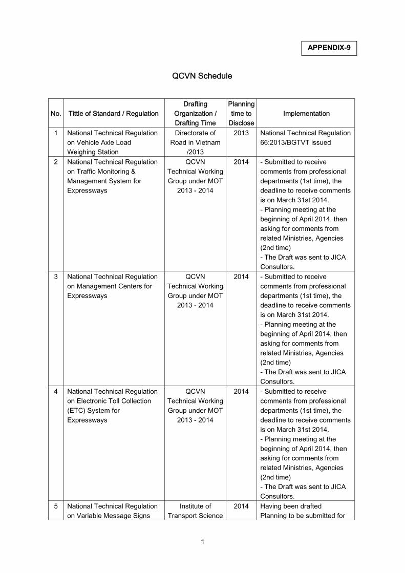
1
QCVN Schedule
No. Tittle of Standard / RegulationDrafting
Organization / Drafting Time
Planning time to
DiscloseImplementation
1 National Technical Regulation on Vehicle Axle Load Weighing Station
Directorate of Road in Vietnam
/2013
2013 National Technical Regulation 66:2013/BGTVT issued
2 National Technical Regulation on Traffic Monitoring & Management System for Expressways
QCVN Technical Working Group under MOT
2013 - 2014
2014 - Submitted to receive comments from professional departments (1st time), the deadline to receive comments is on March 31st 2014. - Planning meeting at the beginning of April 2014, then asking for comments from related Ministries, Agencies (2nd time) - The Draft was sent to JICA Consultors.
3 National Technical Regulation on Management Centers for Expressways
QCVN Technical Working Group under MOT
2013 - 2014
2014 - Submitted to receive comments from professional departments (1st time), the deadline to receive comments is on March 31st 2014. - Planning meeting at the beginning of April 2014, then asking for comments from related Ministries, Agencies (2nd time) - The Draft was sent to JICA Consultors.
4 National Technical Regulation on Electronic Toll Collection (ETC) System for Expressways
QCVN Technical Working Group under MOT
2013 - 2014
2014 - Submitted to receive comments from professional departments (1st time), the deadline to receive comments is on March 31st 2014. - Planning meeting at the beginning of April 2014, then asking for comments from related Ministries, Agencies (2nd time) - The Draft was sent to JICA Consultors.
5 National Technical Regulation on Variable Message Signs
Institute of Transport Science
2014 Having been drafted Planning to be submitted for
APPENDIX-9
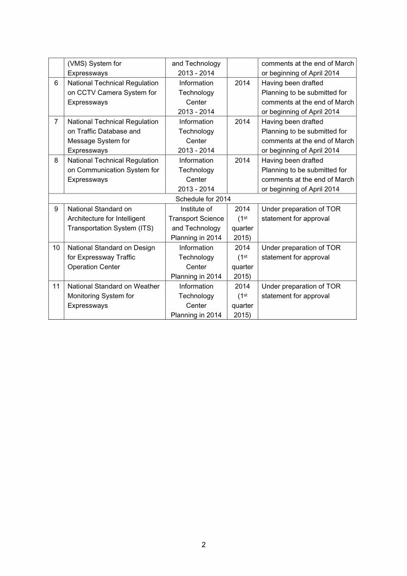
2
(VMS) System for Expressways
and Technology 2013 - 2014
comments at the end of March or beginning of April 2014
6 National Technical Regulation on CCTV Camera System for Expressways
Information Technology
Center 2013 - 2014
2014 Having been drafted Planning to be submitted for comments at the end of March or beginning of April 2014
7 National Technical Regulation on Traffic Database and Message System for Expressways
Information Technology
Center 2013 - 2014
2014 Having been drafted Planning to be submitted for comments at the end of March or beginning of April 2014
8 National Technical Regulation on Communication System for Expressways
Information Technology
Center 2013 - 2014
2014 Having been drafted Planning to be submitted for comments at the end of March or beginning of April 2014
Schedule for 2014 9 National Standard on
Architecture for Intelligent Transportation System (ITS)
Institute of Transport Science and Technology Planning in 2014
2014 (1st
quarter 2015)
Under preparation of TOR statement for approval
10 National Standard on Design for Expressway Traffic Operation Center
Information Technology
Center Planning in 2014
2014 (1st
quarter 2015)
Under preparation of TOR statement for approval
11 National Standard on Weather Monitoring System for Expressways
Information Technology
Center Planning in 2014
2014 (1st
quarter 2015)
Under preparation of TOR statement for approval