module 7 mark heggli innovative hydrology, inc. consultant to the world bank expert real-time...
TRANSCRIPT
Specifications: Instrumentation, Real-time Data Relay, Management, Maintenance and Training
Module 7
Mark HeggliInnovative Hydrology, Inc.
Consultant To The World BankExpert Real-Time Hydrology Information Systems
Notice
Examples that refer to products are intended for illustrative purposes only, and do not imply an
endorsement or recommendation of any particular product

Specifications
Technical Specifications General Informationo Address The Needso Key Requirementso Functional Specifications Vs Vendor Driven Specifications
Instrumentationo Data Loggero Surface Water
• Water Level• Discharge
o Ground Watero Rainfall
Real-time Data Relay Management Maintenance and Training
Technical Specifications General Information
Address the Needso It is recommended that a complete survey of water level stations be
included prior to the final selection of appropriate technologies o The solutions should be determined on a site-by-site basis, as no
single technology will be suitable or sustainable for all gauging locations in India
o There is a desire to use non-contact solutions to measure water level whenever possible, though part of a centric solution may include contact measurement methods
o Lifetime of Equipment• The expected life-time of electronic equipment such as data loggers,
sensors, etc., is expected to be at least 12 years and no longer than 15 years
• After 15 years, hydrologic monitoring equipment generally becomes obsolete, and is usually the maximum timeframe that manufacturers support a given make/model of equipment
• It should be stated in the tender document that current technology will only be offered, and equipment being offered will be supported for a minimum of 10 years after the date of final acceptance of equipment
Technical Specifications General Information:Key Requirements
Accuracy: o The correctness of the reading (how close it is to reality)
Two primary sources of error is drift and stability. Resolution:
o The fineness to which an instrument can be read. Precision:
o The fineness to which and instrument can be read repeatedly and reliably (Usually inversely proportional to range)
Range: o The span of the expected measurements
Technical Specifications General Information
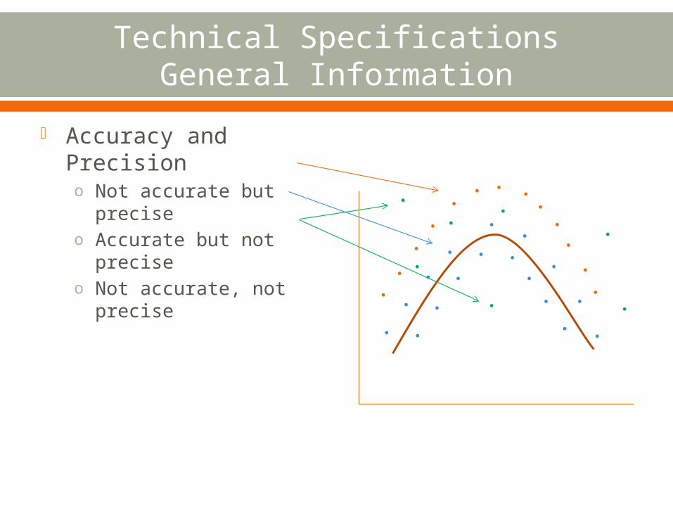
Accuracy and Precisiono Not accurate but
preciseo Accurate but not
preciseo Not accurate, not
precise
Technical Specifications General Information
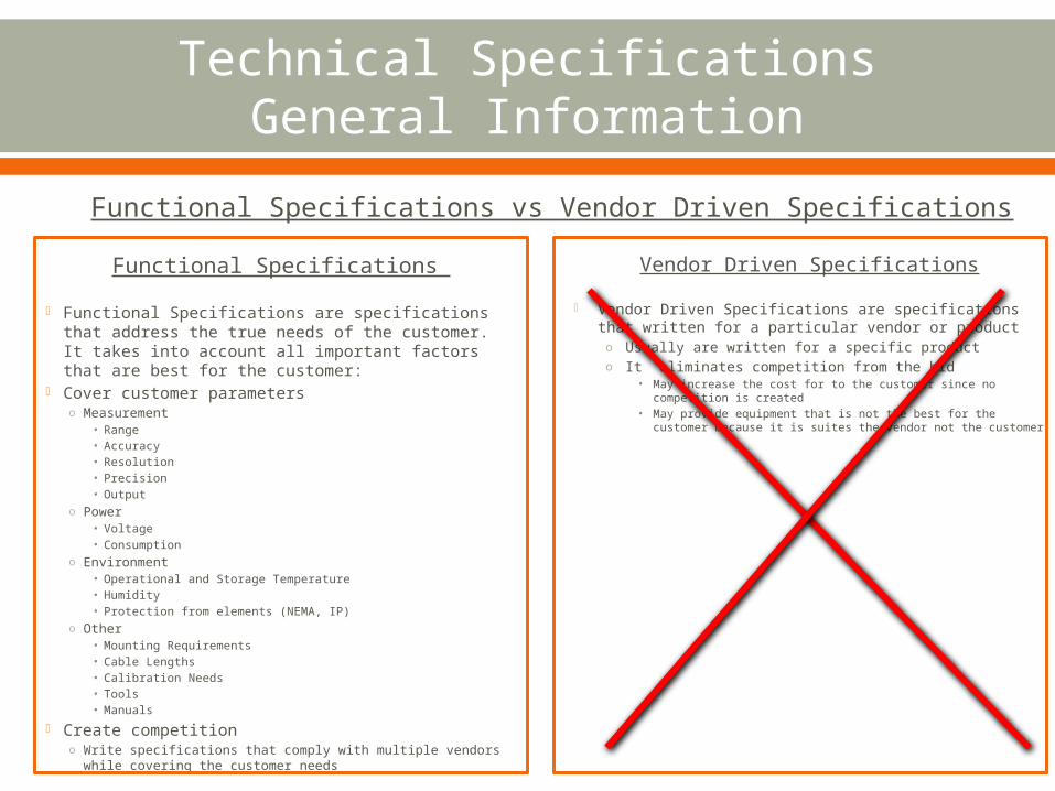
Functional Specifications vs Vendor Driven Specifications
Functional Specifications
Functional Specifications are specifications that address the true needs of the customer. It takes into account all important factors that are best for the customer:
Cover customer parameterso Measurement
• Range • Accuracy • Resolution• Precision• Output
o Power• Voltage• Consumption
o Environment• Operational and Storage Temperature• Humidity• Protection from elements (NEMA, IP)
o Other• Mounting Requirements• Cable Lengths• Calibration Needs• Tools• Manuals
Create competitiono Write specifications that comply with multiple vendors
while covering the customer needs
Vendor Driven Specifications
Vendor Driven Specifications are specifications that written for a particular vendor or producto Usually are written for a specific producto It eliminates competition from the bid
• May increase the cost for to the customer since no competition is created
• May provide equipment that is not the best for the customer because it is suites the vendor not the customer
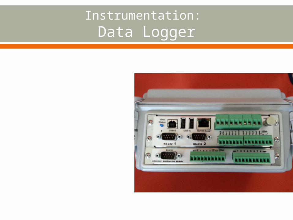
Instrumentation: Data Logger
Instrumentation: Data Logger Continued
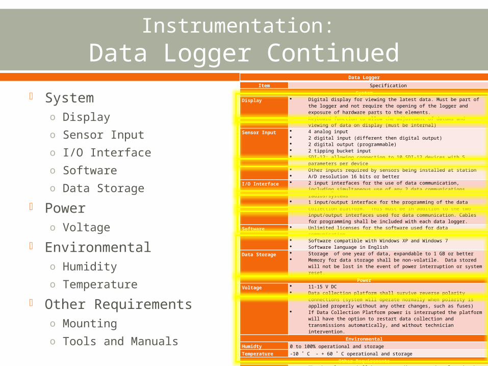
Data Logger
Item Specification
System
Display Digital display for viewing the latest data. Must be part of the logger and not require the opening of the logger and exposure of hardware parts to the elements.
Keyboard function to allow the adjustment of datums and viewing of data on display (must be internal)
Sensor Input 4 analog input 2 digital input (different then digital output) 2 digital output (programmable) 2 tipping bucket input SDI-12; allowing connection to 10 SDI-12 devices with 5 parameters per
device Other inputs required by sensors being installed at station A/D resolution 16 bits or better
I/O Interface 2 input interfaces for the use of data communication, including simultaneous use of any 2 data communications radios/systems
1 input/output interface for the programming of the data collection platform. This must be in addition to the two input/output interfaces used for data communication. Cables for programming shall be included with each data logger.
Software Unlimited licenses for the software used for data communication Software compatible with Windows XP and Windows 7 Software language in English
Data Storage Storage of one year of data, expandable to 1 GB or better Memory for data storage shall be non-volatile. Data stored will not be lost
in the event of power interruption or system reset.
Power
Voltage 11-15 V DC Data collection platform shall survive reverse polarity connections (system
will operate normally when polarity is applied properly without any other changes, such as fuses)
If Data Collection Platform power is interrupted the platform will have the option to restart data collection and transmissions automatically, and without technician intervention.
Environmental
Humidty 0 to 100% operational and storage
Temperature -10 ˚ C - + 60 ˚ C operational and storage
Other Requirements
Mounting The data logger shall be easy to dismount and replace in the event of malfunction.
Data logger mounting supports and other accessories included. Enclosure shall be designed to dissuade or otherwise prevent unauthorized
access. All wire runs between the data logger, sensors and power supply shall be
similarly designed. All parts, cables, components required to successfully operate the
products as a complete system.Tools and Manuals
Complete toolkit for installation and routine maintenance giving full details. (number of pieces and type)
Full documentation and maintenance instructions in English. (1 per station)
Systemo Displayo Sensor Inputo I/O Interfaceo Softwareo Data Storage
Powero Voltage
Environmentalo Humidityo Temperature
Other Requirementso Mountingo Tools and Manuals
Instrumentation: Surface Water Level - Bubbler
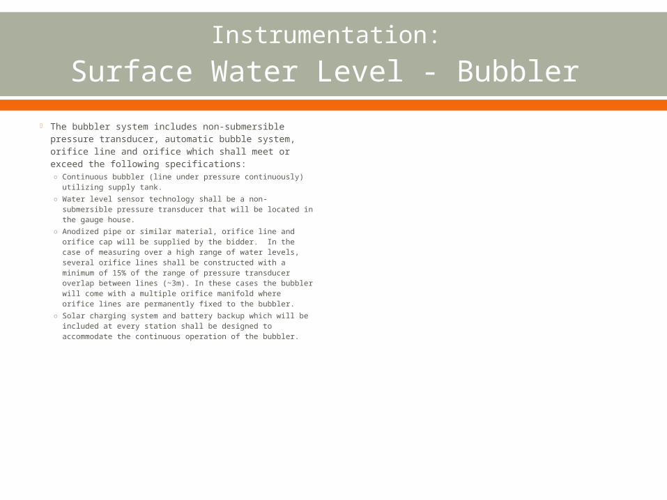
The bubbler system includes non-submersible pressure transducer, automatic bubble system, orifice line and orifice which shall meet or exceed the following specifications:o Continuous bubbler (line under pressure
continuously) utilizing supply tank.o Water level sensor technology shall be a non-
submersible pressure transducer that will be located in the gauge house.
o Anodized pipe or similar material, orifice line and orifice cap will be supplied by the bidder. In the case of measuring over a high range of water levels, several orifice lines shall be constructed with a minimum of 15% of the range of pressure transducer overlap between lines (~3m). In these cases the bubbler will come with a multiple orifice manifold where orifice lines are permanently fixed to the bubbler.
o Solar charging system and battery backup which will be included at every station shall be designed to accommodate the continuous operation of the bubbler.
Instrumentation: Surface Water Level – Bubbler Continued
System Water Level
o Rangeo Accuracyo Resolutiono Outputo Calibrationo Orifice Lineo Air Drying Systemo Sensor Typeo Purgeo Bubble Rate
Powero Voltageo Consumption
Environmentalo Protectiono Humidityo Temperature
Other Requirementso Mountingo Tools and Manuals
Bubbler Water Level
Item Specification
System
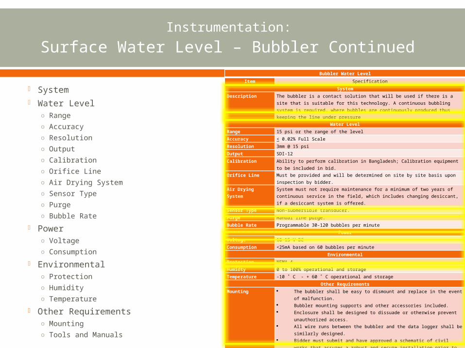
Description The bubbler is a contact solution that will be used if there is a site that is suitable for this technology. A continuous bubbling system is required, where bubbles are continuously produced thus keeping the line under pressure
Water Level
Range 15 psi or the range of the level
Accuracy < 0.02% Full Scale
Resolution 3mm @ 15 psi
Output SDI-12
Calibration Ability to perform calibration in Bangladesh; Calibration equipment to be included in bid.
Orifice Line Must be provided and will be determined on site by site basis upon inspection by bidder.
Air Drying System
System must not require maintenance for a minimum of two years of continuous service in the field, which includes changing desiccant, if a desiccant system is offered.
Sensor Type Non-submersible transducer.
Purge Manual line purge.
Bubble Rate Programmable 30-120 bubbles per minute
Power
Voltage 10-15 V DC
Consumption <25mA based on 60 bubbles per minute
Environmental
Protection NEMA 4
Humidty 0 to 100% operational and storage
Temperature -10 ˚ C - + 60 ˚ C operational and storage
Other Requirements
Mounting The bubbler shall be easy to dismount and replace in the event of malfunction.
Bubbler mounting supports and other accessories included. Enclosure shall be designed to dissuade or otherwise prevent
unauthorized access. All wire runs between the bubbler and the data logger shall be similarly
designed. Bidder must submit and have approved a schematic of civil works that
assures a robust and secure installation prior to start of work. Orifice line must be protected by conduit.
Tools and Manuals
Complete toolkit for installation and routine maintenance giving full details. (number of pieces and type)
Full documentation and maintenance instructions in English. (1 per station)
Instrumentation: Surface Water Level- Shaft Encoder
Shaft Encoder
Instrumentation: Surface Water Level- Shaft Encoder Continued
Site Conditions Sensor Type Resolution Output Accessories Enclosure Tools and Manuals
Shaft EncoderItem Specification
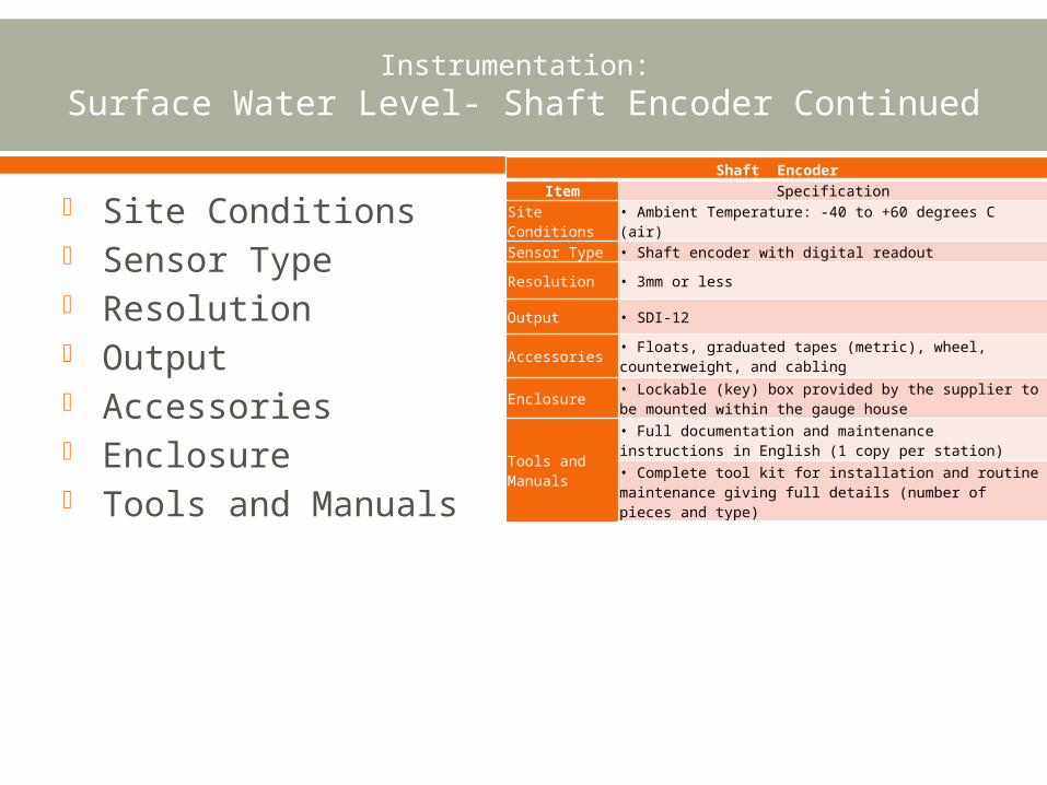
Site Conditions • Ambient Temperature: -40 to +60 degrees C (air)Sensor Type • Shaft encoder with digital readout
Resolution • 3mm or less
Output • SDI-12
Accessories • Floats, graduated tapes (metric), wheel, counterweight, and cabling
Enclosure • Lockable (key) box provided by the supplier to be mounted within the gauge house
Tools and Manuals
• Full documentation and maintenance instructions in English (1 copy per station)
• Complete tool kit for installation and routine maintenance giving full details (number of pieces and type)
Instrumentation: Surface Water Level – Submersible Pressure Transducer
Instrumentation: Surface Water Level – Submersible Pressure Transducer Cont.
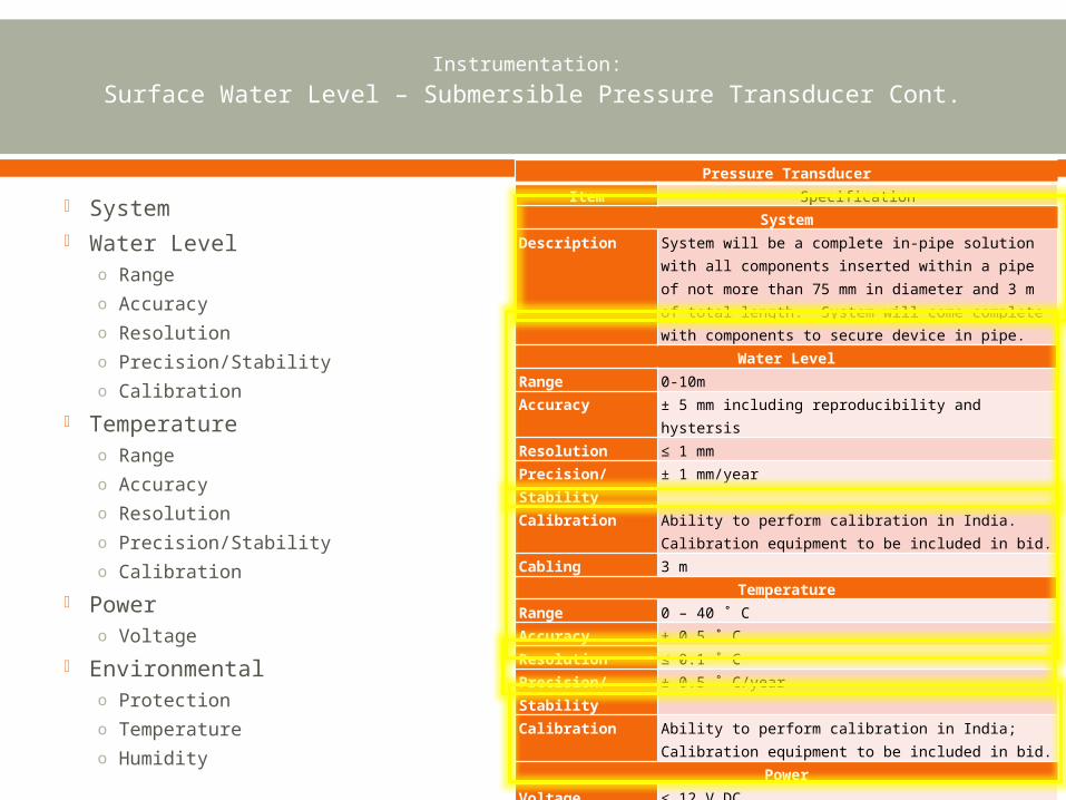
System Water Level
o Rangeo Accuracyo Resolutiono Precision/Stabilityo Calibration
Temperatureo Rangeo Accuracyo Resolutiono Precision/Stabilityo Calibration
Powero Voltage
Environmentalo Protectiono Temperatureo Humidity
Pressure Transducer
Item Specification
System
Description System will be a complete in-pipe solution with all components inserted within a pipe of not more than 75 mm in diameter and 3 m of total length. System will come complete with components to secure device in pipe.
Water Level
Range 0-10m
Accuracy ± 5 mm including reproducibility and hystersis
Resolution ≤ 1 mm
Precision/Stability
± 1 mm/year
Calibration Ability to perform calibration in India. Calibration equipment to be included in bid.
Cabling 3 m
Temperature
Range 0 – 40 ˚ C
Accuracy ± 0.5 ˚ C
Resolution ≤ 0.1 ˚ C
Precision/Stability
± 0.5 ˚ C/year
Calibration Ability to perform calibration in India; Calibration equipment to be included in bid.
Power
Voltage ≤ 12 V DC
Environmental
Protection All components IP-68
Temperature 0 to 50 ˚ C operational / -10 to 70 ˚ C storage
Humidty 0 to 100% operational and storage
Instrumentation: Surface Water Level - Ultrasonic
Instrumentation: Surface Water Level – Ultrasonic Continued
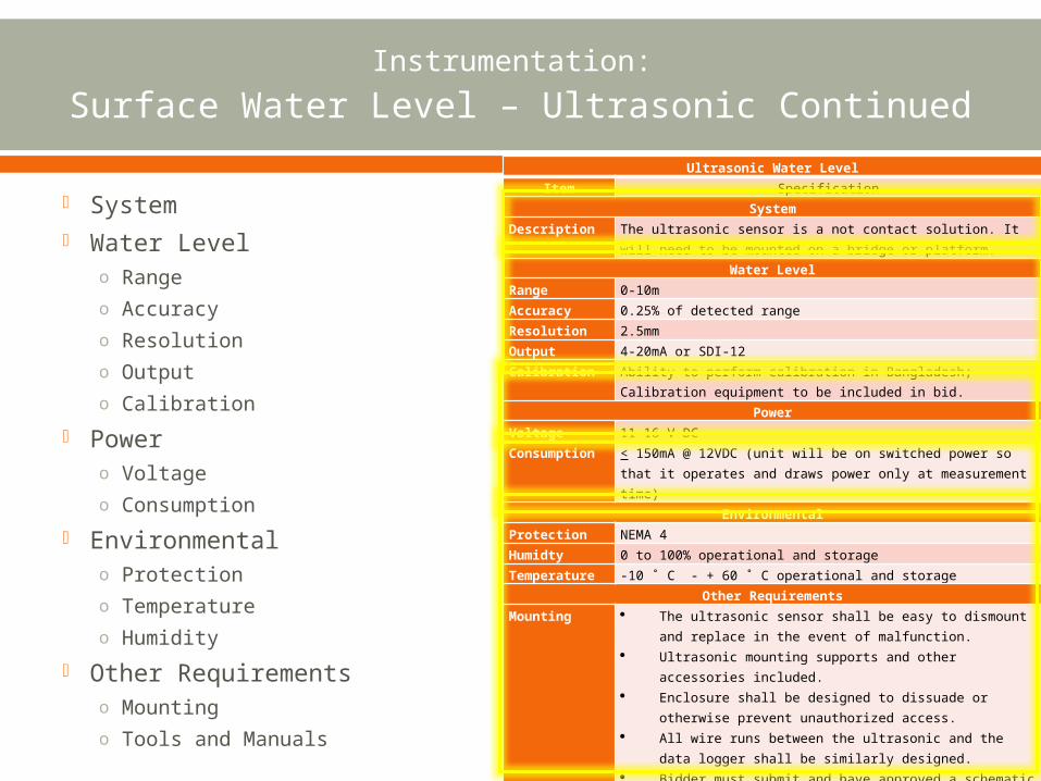
Ultrasonic Water LevelItem Specification
SystemDescription The ultrasonic sensor is a not contact solution. It will need to
be mounted on a bridge or platform.Water Level
Range 0-10mAccuracy 0.25% of detected rangeResolution 2.5mmOutput 4-20mA or SDI-12Calibration Ability to perform calibration in Bangladesh; Calibration
equipment to be included in bid.Power
Voltage 11-16 V DCConsumption < 150mA @ 12VDC (unit will be on switched power so that it
operates and draws power only at measurement time)Environmental
Protection NEMA 4Humidty 0 to 100% operational and storageTemperature -10 ˚ C - + 60 ˚ C operational and storage
Other RequirementsMounting The ultrasonic sensor shall be easy to dismount and
replace in the event of malfunction. Ultrasonic mounting supports and other accessories
included. Enclosure shall be designed to dissuade or otherwise
prevent unauthorized access. All wire runs between the ultrasonic and the data logger
shall be similarly designed. Bidder must submit and have approved a schematic of
civil works that assures a robust and secure installation prior to start of work.
Tools and Manuals
Complete toolkit for installation and routine maintenance giving full details. (number of pieces and type)
Full documentation and maintenance instructions in English. (1 per station)
System Water Level
o Rangeo Accuracyo Resolutiono Outputo Calibration
Powero Voltageo Consumption
Environmentalo Protectiono Temperatureo Humidity
Other Requirementso Mountingo Tools and Manuals
Instrumentation: Surface Water Level - Radar

Instrumentation: Surface Water Level – Radar Continued
Radar Water LevelItem Specification
SystemDescription The radar is a preffered non contact solution. The radar will
be connected to the data logger specified Water Level
Range 1-30mAccuracy ≤ .03% full scale Resolution ≤ 3 mmOutput SDI-12Calibration Ability to perform calibration in Bangladesh; Calibration
equipment to be included in bid.Cabling Must be provided and will be determined on site by site basis
upon inspection by bidder.Power
Voltage 10-15 V DCConsumption Active: <20mA, Sleep: <10mA
EnvironmentalProtection NEMA 4Humidty 0 to 100% operational and storageTemperature -10 ˚ C - + 60 ˚ C operational and storage
Other RequirementsMounting The radar shall be easy to dismount and replace in the
event of malfunction. Sensor mounting supports and other accessories
included. Enclosure shall be designed to dissuade or otherwise
prevent unauthorized access. All wire runs between the radar and the data logger
shall be similarly designed. Bidder must submit and have approved a schematic of
civil works that assures a robust and secure installation prior to start of work.
Tools and Manuals
Complete toolkit for installation and routine maintenance giving full details. (number of pieces and type)
Full documentation and maintenance instructions in English. (1 per station)
System Water Level
o Rangeo Accuracyo Resolutiono Outputo Calibrationo Cabling
Powero Voltageo Consumption
Environmentalo Protectiono Humidityo Temperature
Other Requirementso Mountingo Tools and Manuals
Instrumentation: Discharge – Radar Discharge
Instrumentation: Discharge – Radar Discharge
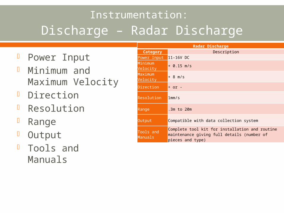
Power Input Minimum and
Maximum Velocity Direction Resolution Range Output Tools and Manuals
Radar DischargeCategory Description
Power Input 11-16V DCMinimum Velocity + 0.15 m/s
Maximum Velocity + 8 m/s
Direction + or -
Resolution 1mm/s
Range .3m to 20m
Output Compatible with data collection system
Tools and Manuals
Complete tool kit for installation and routine maintenance giving full details (number of pieces and type)
Instrumentation: Discharge - ADCP
Side Looking
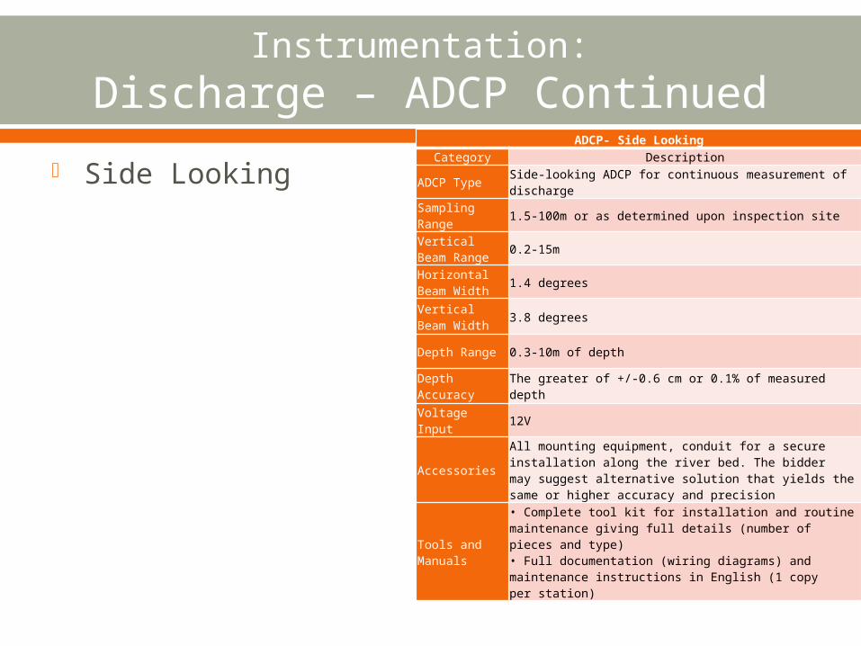
Instrumentation: Discharge – ADCP Continued
Side LookingADCP- Side Looking
Category Description
ADCP TypeSide-looking ADCP for continuous measurement of discharge
Sampling Range 1.5-100m or as determined upon inspection site
Vertical Beam Range 0.2-15m
Horizontal Beam Width 1.4 degrees
Vertical Beam Width
3.8 degrees
Depth Range 0.3-10m of depth
Depth Accuracy The greater of +/-0.6 cm or 0.1% of measured depth
Voltage Input 12V
Accessories
All mounting equipment, conduit for a secure installation along the river bed. The bidder may suggest alternative solution that yields the same or higher accuracy and precision
Tools and Manuals
• Complete tool kit for installation and routine maintenance giving full details (number of pieces and type)• Full documentation (wiring diagrams) and maintenance instructions in English (1 copy per station)
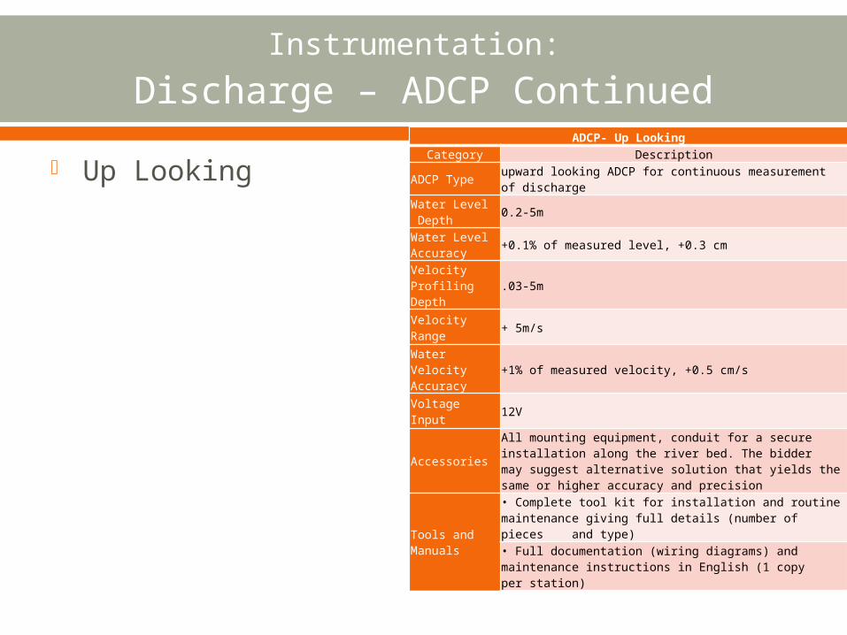
Instrumentation: Discharge – ADCP Continued
Up LookingADCP- Up Looking
Category Description
ADCP Typeupward looking ADCP for continuous measurement of discharge
Water Level Depth 0.2-5m
Water Level Accuracy +0.1% of measured level, +0.3 cm
Velocity Profiling Depth .03-5m
Velocity Range + 5m/s
Water Velocity Accuracy
+1% of measured velocity, +0.5 cm/s
Voltage Input 12V
Accessories
All mounting equipment, conduit for a secure installation along the river bed. The bidder may suggest alternative solution that yields the same or higher accuracy and precision
Tools and Manuals
• Complete tool kit for installation and routine maintenance giving full details (number of pieces and type)• Full documentation (wiring diagrams) and maintenance instructions in English (1 copy per station)
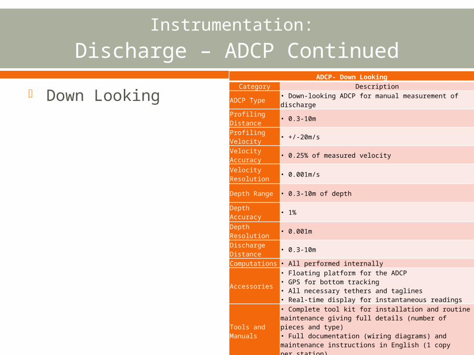
Instrumentation: Discharge – ADCP Continued
Down LookingADCP- Down Looking
Category Description
ADCP Type• Down-looking ADCP for manual measurement of discharge
Profiling Distance • 0.3-10m
Profiling Velocity • +/-20m/s
Velocity Accuracy • 0.25% of measured velocity
Velocity Resolution
• 0.001m/s
Depth Range • 0.3-10m of depth
Depth Accuracy • 1%
Depth Resolution • 0.001m
Discharge Distance • 0.3-10m
Computations • All performed internally
Accessories
• Floating platform for the ADCP• GPS for bottom tracking• All necessary tethers and taglines• Real-time display for instantaneous readings
Tools and Manuals
• Complete tool kit for installation and routine maintenance giving full details (number of pieces and type)• Full documentation (wiring diagrams) and maintenance instructions in English (1 copy per station)
Instrumentation: Ground Water – Submersible Pressure Transducer
Instrumentation: Ground Water – Submersible Pressure Transducer
Cont.Item Specification
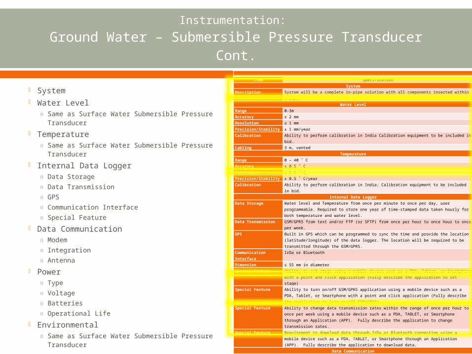
SystemDescription System will be a complete in-pipe solution with all components inserted within a pipe.
Water LevelRange 0-3mAccuracy ± 2 mmResolution ≤ 1 mmPrecision/Stability ± 1 mm/yearCalibration Ability to perform calibration in India Calibration equipment to be included in bid.
Cabling 3 m, ventedTemperature
Range 0 – 40 ˚ CAccuracy ± 0.5 ˚ CResolution ≤ 0.1 ˚ CPrecision/Stability ± 0.5 ˚ C/year Calibration Ability to perform calibration in India; Calibration equipment to be included in bid.
Internal Data LoggerData Storage Water level and Temperature from once per minute to once per day, user programmable.
Required to store one year of time-stamped data taken hourly for both temperature and water level.
Data Transmission GSM/GPRS from text and/or FTP (or SFTP) from once per hour to once hour to once per week.
GPS Built in GPS which can be programmed to sync the time and provide the location (latitude/longitude) of the data logger. The location will be required to be transmitted through the GSM/GPRS.
Communication Interface
IrDa or Bluetooth
Dimension ≤ 55 mm in diameterSpecial Feature Ability to set stage using a mobile device such as a PDA, Tablet, or Smartphone with a point
and click application (Fully describe the application to set stage)
Special Feature Ability to turn on/off GSM/GPRS application using a mobile device such as a PDA, Tablet, or Smartphone with a point and click application (Fully describe the application to turn on/off GSM/GPRS)
Special Feature Ability to change data transmission rates within the range of once per hour to once per week using a mobile device such as a PDA, TABLET, or Smartphone through an Application (APP). Fully describe the application to change transmission rates.
Special Feature Requirement to download data through IrDa or Bluetooth connection using a mobile device such as a PDA, TABLET, or Smartphone through an Application (APP). Fully describe the application to download data.
Data CommunicationModem GSM/GPRS compatible with frequencies available in Bangladesh (Provide data sheet or
example of compliance)Integration Modem will be integrated into the data logger enclosureAntenna Built in weatherproof with no external appearance of an antenna
PowerType Self-contained (no external charging device required)Voltage ≤ 12 V DCBatteries Commonly available in Bangladesh (i.e. 1.5V AA, AAA, C, or D cells)Operational Life Data Measurement/Logging and GSM/GPRS data communication 1 per hr, one year minimum
per set of batteriesEnvironmental
Protection All components IP-68Temperature 0 to 50 ˚ C operational / -10 to 70 ˚ C storageHumidty 0 to 100% operational and storage
System Water Level
o Same as Surface Water Submersible Pressure Transducer
Temperatureo Same as Surface Water Submersible
Pressure Transducer Internal Data Logger
o Data Storageo Data Transmissiono GPSo Communication Interfaceo Special Feature
Data Communicationo Modemo Integrationo Antenna
Powero Typeo Voltageo Batterieso Operational Life
Environmentalo Same as Surface Water Submersible
Pressure Transducer

Instrumentation:
Rainfall – Tipping Bucket
Instrumentation:
Rainfall – Tipping BucketRainfall (Tipping Bucket)
Item Specification
System
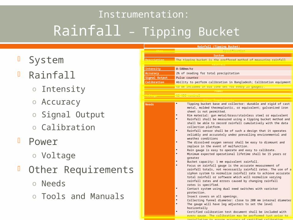
Description The tipping bucket is the preffered method of measuring rainfall
Rainfall
Intensity 0-500mm/hr
Accuracy 2% of reading for total precipitation
Signal Output Pulse counter
Calibration Ability to perform calibration in Bangladesh; Calibration equipment to be included in bid (one set for every 25 gauges).
Power
Voltage 12 VDC nominal
Other Requirements
Needs Tipping bucket base and collector: durable and rigid of cast metal, molded thermoplastic, or equivalent; galvanized iron sheet is not permitted.
Rim material: gun metal/brass/stainless steel or equivalent Rainfall shall be measured using a tipping bucket method and shall be
able to record rainfall cumulatively with the data collection platform. Rainfall sensor shall be of such a design that it operates reliably and
accurately under prevailing environmental and weather conditions The dissolved oxygen sensor shall be easy to dismount and replace in
the event of malfunction. Rain gauge is easy to operate and easy to calibrate. Minimum expected operational lifetime shall be 15 years or greater Bucket capacity: 1 mm equivalent rainfall. Focus on rainfall gauge is the accurate measurement of rainfall totals,
not necessarily rainfall rates. The use of a siphon system to normalize rainfall rate to achieve accurate total rainfall or software which will normalize varying rainfall rates and errors caused by changing rainfall rates is specified.
Contact system using dual reed switches with varistor protection. Insect covers on all openings. Collecting funnel diameter: close to 200 mm internal diameter The gauge will have leg adjusters to set the level horizontally Certified calibration test document shall be included with every gauge.
The calibration may be performed just prior to installation to assure accuracy of certified calibration test.
Ability to service tipping bucket gauge without re-leveling the gauge. Calibration kit for tipping buckets. (4 units) Necessary cables to connect precipitation gauge to data logger as
required. All wire runs between the tipping bucket and the data logger shall be
similarly designed. Bidder must submit and have approved a schematic of civil works that
assures a robust and secure installation prior to start of work.Tools and Manuals
Complete toolkit for installation and routine maintenance giving full details. (number of pieces and type)
Full documentation and maintenance instructions in English. (1 per station)
System Rainfall
o Intensityo Accuracyo Signal Outputo Calibration
Powero Voltage
Other Requirementso Needso Tools and Manuals
Real-time Data Relay
Management
Maintenance and Training