fmb1yx user manual v0...fmb1yx user manual v0 ... 9
TRANSCRIPT

FMB1YX User Manual
V0.10

2
Table of contents
1 INTRODUCTION ................................................................................................................... 11
1.1 ATTENTION .......................................................................................................................... 11 1.2 INSTRUCTIONS OF SAFETY ....................................................................................................... 11 1.3 LEGAL NOTICE ...................................................................................................................... 12 1.4 ABOUT DOCUMENT ............................................................................................................... 12
2 BASIC DESCRIPTION ............................................................................................................. 12
2.1 PACKAGE CONTENTS .............................................................................................................. 12 2.2 BASIC CHARACTERISTICS ......................................................................................................... 13 2.3 TECHNICAL FEATURES............................................................................................................. 15 2.4 TECHNICAL INFORMATION ABOUT INTERNAL BATTERY................................................................... 17 2.5 ELECTRICAL CHARACTERISTICS .................................................................................................. 17 2.6 ABSOLUTE MAXIMUM RATINGS ............................................................................................... 19
3 CONNECTION, PINOUT, ACCESSORIES .................................................................................. 20
3.1 HOW TO INSERT SIM CARD INTO FMB1YX DEVICE: .................................................................... 20 3.2 HOW TO ADD MICROSD CARD INTO FMB1YX DEVICE ................................................................. 21 3.3 INSTALLING FMB1YX DRIVERS ................................................................................................ 21 3.4 FMB120 AND FMB122 2X6 SOCKET PINOUT ........................................................................... 23 3.5 FMB125 2X6 SOCKET PINOUT ................................................................................................ 24 3.6 ACCESSORIES........................................................................................................................ 25 3.7 NAVIGATE LED ..................................................................................................................... 28 3.8 STATUS LED ........................................................................................................................ 28
4 OPERATIONAL BASICS .......................................................................................................... 28
4.1 OPERATIONAL PRINCIPALS....................................................................................................... 28 4.2 SLEEP MODES ....................................................................................................................... 29
4.2.1 GPS Sleep mode ...................................................................................................... 29 4.2.2 Deep Sleep mode .................................................................................................... 29 4.2.3 Online Deep Sleep mode ......................................................................................... 30
4.3 VIRTUAL ODOMETER .............................................................................................................. 30 4.4 FEATURES ............................................................................................................................ 31
4.4.1 ECO driving/Green driving Scenarios ...................................................................... 31 4.4.2 OverSpeeding Scenario. .......................................................................................... 32 4.4.3 Jamming detection ................................................................................................. 32 4.4.4 Trip.......................................................................................................................... 32 4.4.5 DOUT Control Via Call ............................................................................................. 32 4.4.6 Immobilizer ............................................................................................................. 32 4.4.7 iButton read notification ........................................................................................ 33 4.4.8 GPS Fuel Counter .................................................................................................... 33
4.5 ACCELEROMETER FEATURES .................................................................................................... 33 4.5.1 Excessive Idling ....................................................................................................... 33 4.5.2 Unplug Detection .................................................................................................... 33 4.5.3 Towing Detection.................................................................................................... 33 4.5.4 Crash Detection ...................................................................................................... 33
4.6 BLUETOOTH ......................................................................................................................... 33 4.7 AUTO GEOFENCE .................................................................................................................. 34 4.8 MANUAL GEOFENCE .............................................................................................................. 34 4.9 IBUTTON LIST ....................................................................................................................... 34
5 CONFIGURATION ................................................................................................................. 34
5.1 CONFIGURATOR .................................................................................................................... 34 5.1.1 Main Buttons description: ...................................................................................... 36 5.1.2 Keyword SMS (GPRS) commands: .......................................................................... 36

3
5.1.3 Keyword configuration with TCP ............................................................................ 36 5.2 STATUS INFO ........................................................................................................................ 36 5.3 SECURITY INFO ..................................................................................................................... 37 5.4 SYSTEM SETTINGS.................................................................................................................. 37 5.5 GPRS ................................................................................................................................. 40 5.6 SMS/CALL SETTINGS ............................................................................................................. 41 5.7 GSM OPERATORS, SIM1 ROAMING AND SIM2 ROAMING/ HOME OPERATOR LIST, BLACKLIST OPERATOR
LIST 43 5.7.1 Dual SIM ................................................................................................................. 44
5.8 DATA ACQUISITION MODE SETTINGS ........................................................................................ 46 5.9 FEATURES SETTINGS ............................................................................................................... 48
5.9.1 Green Driving .......................................................................................................... 49 5.9.1.1 Data output......................................................................................................................... 50 5.9.1.2 Auto Calibaration ................................................................................................................ 50
5.9.2 Over Speeding ......................................................................................................... 51 5.9.3 Jamming ................................................................................................................. 51 5.9.4 Use authorized numbers to control DOUT via call ................................................. 52 5.9.5 Immobilizer ............................................................................................................. 52 5.9.6 iButton read notification ........................................................................................ 53 5.9.7 GPS Fuel Counter .................................................................................................... 53
5.10 ACCELEROMETER FEATURES .................................................................................................... 53 5.10.1 Excessive Idling ....................................................................................................... 54 5.10.2 Unplug Detection .................................................................................................... 54 5.10.3 Towing Detection.................................................................................................... 54 5.10.4 Crash Detection ...................................................................................................... 55
5.11 DOUT ON/OFF DURATION ................................................................................................... 56 5.12 DOUT CONTROL DEPENDING ON FUNCTIONALITY PRIORITY ........................................................... 57 5.13 AUTOGEOFENCING SETTINGS .................................................................................................. 57 5.14 MANUAL GEOFENCE .............................................................................................................. 58 5.15 TRIP \ ODOMETER ................................................................................................................ 59
5.15.1 Trip settings ............................................................................................................ 59 5.15.2 Advanced Trip Settings ........................................................................................... 60 5.15.3 Odometer ............................................................................................................... 61
5.16 BLUETOOTH ......................................................................................................................... 62 5.16.1 General functionality .............................................................................................. 62 5.16.2 How to connect Bluetooth Hands Free adapter to FMB device .............................. 64
5.16.2.1 Bluetooth settings configuration ...................................................................................... 64 5.16.2.2 Connecting Bluetooth Hands Free adapter ...................................................................... 66
5.16.3 Device’s log using your mobile phone. ................................................................... 66 5.16.4 Device debug over Android smartphone ................................................................ 67 5.16.5 How to connect OBD II Bluetooth Dongle to FMB device ....................................... 68
5.16.5.1 Bluetooth settings configuration ...................................................................................... 68 5.16.5.2 Connecting to Bluetooth OBD II dongle ............................................................................ 70 5.16.5.3 Supported Bluetooth OBD II dongles ................................................................................ 71
5.17 SMS EVENTS ........................................................................................................................ 71 5.18 IBUTTON LIST ....................................................................................................................... 73 5.19 I/O SETTINGS ....................................................................................................................... 73
5.19.1 Operand On Exit ..................................................................................................... 73 5.19.2 Operand On Entrance ............................................................................................. 74 5.19.3 Operand On Both .................................................................................................... 74 5.19.4 Operand Monitoring ............................................................................................... 74 5.19.5 Operand On Hysteresis ........................................................................................... 75 5.19.6 Operand On Change ............................................................................................... 75 5.19.7 Operand On Delta Change ...................................................................................... 75 5.19.8 Avg const (Averaging parameter description) ........................................................ 75 5.19.9 OBD II (Bluetooth) and LVCAN I/O elements .......................................................... 76 5.19.10 FMB125 RS232\RS485 parameters configuration .................................................. 76
5.19.10.1 External UART working mode ......................................................................................... 76 5.19.10.2 RS232 working mode ...................................................................................................... 77

4
5.19.10.3 RS232 Baudrate and parity ............................................................................................. 77 5.19.10.4 RS232 TCP Binary mode settings .................................................................................... 78 5.19.10.5 RS232 Garmin Mode settings ......................................................................................... 78 5.19.10.6 RS485 working mode ...................................................................................................... 78 5.19.10.7 RS485 Baudrate .............................................................................................................. 79 5.19.10.8 RS485 LLS Sensors ........................................................................................................... 79
6 RS232 AND RS485 ................................................................................................................ 79
6.1 RS485 INTERFACE ................................................................................................................ 79 6.2 RS485 MODES ..................................................................................................................... 80
6.2.1 RS485 transmit (FMB log) mode ............................................................................. 80 6.2.2 RS485 transmit (GNSS NMEA) mode ...................................................................... 80 6.2.3 RS485 receive (LLS) mode ....................................................................................... 81 6.2.4 RS485 TCP (ASCII, Binary) mode ............................................................................. 81
6.3 RS232 INTERFACE ................................................................................................................ 81 6.4 RS232 MODES ..................................................................................................................... 81
6.4.1 RS232 LCD mode ..................................................................................................... 81 6.4.2 RS232 RFID HID/RFID MF7 mode............................................................................ 82 6.4.3 RS232 GARMIN mode ............................................................................................. 83
6.5 GARMIN PROTOCOLS ............................................................................................................. 84 6.5.1 Standard protocols ................................................................................................. 84 6.5.2 Enchanced protocols ............................................................................................... 85 6.5.3 Supported features on TAVL client application ...................................................... 85 6.5.4 Text messaging ....................................................................................................... 85 6.5.5 Destination message .............................................................................................. 85 6.5.6 ETA request message .............................................................................................. 85
7 FMB1YX WITH LV-CAN200 AND ALL-CAN300 CAN ADAPTERS .............................................. 85
7.1 PURPOSE OF CAN ADAPTERS LV-CAN200 AND ALL-CAN30 ....................................................... 85 7.2 LV-CAN200 AND ALL-CAN300 PROGRAM NUMBER SELECTION .................................................. 86
7.2.1 LV-CAN200 and ALL-CAN300 program number configuration via SMS command . 86 7.2.2 LV-CAN200 and ALL-CAN300 program number configuration via configurator .... 86 7.2.3 Selecting LV-CAN200 and ALL-CAN300 program number manually ...................... 86
7.3 SIMPLE-CAN - CONTACTLESS CAN-BUS READER ...................................................................... 88 7.4 CONNECTING FMB1YX CAN ADAPTERS ALL-CAN300 AND LV-CAN200 ...................................... 89 7.5 FMB1YX ALL-CAN300 AND LV-CAN200 PARAMETERS CONFIGURATION ..................................... 90 7.6 SEND DATA WITH 0, IF IGNITION IS OFF ...................................................................................... 94
8 SMS/GPRS COMMAND LIST ................................................................................................. 95
8.1 SMS/GPRS COMMAND LIST................................................................................................... 95 8.1.1 getinfo .................................................................................................................... 98 8.1.2 getver ..................................................................................................................... 99 8.1.3 getstatus ................................................................................................................. 99 8.1.4 getgps ..................................................................................................................... 99 8.1.5 getio ...................................................................................................................... 100 8.1.6 ggps ...................................................................................................................... 100 8.1.7 readio # ................................................................................................................. 100 8.1.8 getparam .............................................................................................................. 100 8.1.9 setparam .............................................................................................................. 100 8.1.10 flush #,#,#,#,#,#,# ................................................................................................. 101 8.1.11 countrecs .............................................................................................................. 101 8.1.12 deleterecords ........................................................................................................ 101 8.1.13 setdigout ............................................................................................................... 102 8.1.14 battery .................................................................................................................. 102 8.1.15 fc_reset ................................................................................................................. 102 8.1.16 towingreact .......................................................................................................... 102 8.1.17 odoset:# ................................................................................................................ 102 8.1.18 odoget .................................................................................................................. 102

5
8.1.19 btgetlist # .............................................................................................................. 102 8.1.20 obdinfo ................................................................................................................. 103 8.1.21 faultcodes ............................................................................................................. 103 8.1.22 setkey # # .............................................................................................................. 103 8.1.23 delkey # # .............................................................................................................. 103 8.1.24 bbread # ............................................................................................................... 103 8.1.25 bbinfo # ................................................................................................................. 103 8.1.26 sdformat ............................................................................................................... 104 8.1.27 lvcansetprog # ...................................................................................................... 104 8.1.28 lvcangetprog ......................................................................................................... 104 8.1.29 lvcangetinfo .......................................................................................................... 104 8.1.30 lvcanclear # ........................................................................................................... 104 8.1.31 allcanmode ........................................................................................................... 104 8.1.32 lvcanmode ............................................................................................................ 104 8.1.33 lvcanfaultcodes ..................................................................................................... 104
9 PARAMETER LIST ............................................................................................................... 105
9.1 SYSTEM PARAMETERS .......................................................................................................... 105 9.1.1 Sleep Mode (ID=102) ............................................................................................ 105 9.1.2 Sleep timeout (ID=103) ......................................................................................... 105 9.1.3 Movement Source (ID=100) .................................................................................. 105 9.1.4 Static Navigation (ID=106) ................................................................................... 105 9.1.5 Analog input value range (ID=111) ....................................................................... 106 9.1.6 Static Navigation Settings (ID=112) ...................................................................... 106 9.1.7 Saving/Sending without time synchronization (ID=107) ...................................... 106 9.1.8 GNSS Source (ID=109) ........................................................................................... 106 9.1.9 Ignition settings (ID=101) ..................................................................................... 106 9.1.10 High voltage level (ID=104) .................................................................................. 107 9.1.11 Low voltage level (ID=105) ................................................................................... 107 9.1.12 Movement Start Delay(s) (ID=19001) ................................................................... 107 9.1.13 Movement Stop Delay(s) (ID=19002) ................................................................... 108 9.1.14 Led indication (ID=108) ......................................................................................... 108 9.1.15 Synchronization settings (ID=900) ........................................................................ 108 9.1.16 NTP Resync (ID=901)............................................................................................. 108 9.1.17 NTP server 1 (ID=902) ........................................................................................... 108 9.1.18 NTP server 2 (ID=903) ........................................................................................... 109 9.1.19 Battery charge mode (ID=110) ............................................................................. 109
9.2 GPRS PARAMETERS ............................................................................................................ 109 9.2.1 Sorting (ID=1002) ................................................................................................. 109 9.2.2 Open Link Timeout (ID=1000) ............................................................................... 109 9.2.3 Server Response Timeout (ID=1001) ..................................................................... 109 9.2.4 SIM1 GPRS content activation (ID=2000) ............................................................ 110 9.2.5 SIM1 APN Name (ID=2001) ................................................................................. 110 9.2.6 SIM1 APN username (ID=2002) .......................................................................... 110 9.2.7 SIM1 APN Password (ID=2003) ........................................................................... 111 9.2.8 SIM2 GPRS content activation (ID=2011) ............................................................ 111 9.2.9 SIM2 APN Name (ID=2012) ................................................................................. 111 9.2.10 SIM2 APN username (ID=2013) .......................................................................... 111 9.2.11 SIM2 APN Password (ID=2014) ........................................................................... 112 9.2.12 Domain (ID=2004) ................................................................................................ 112 9.2.13 Target Server Port (ID=2005) ................................................................................ 112 9.2.14 Protocol (ID=2006) .............................................................................................. 112 9.2.15 Backup Server Domain (ID=2007) ......................................................................... 112 9.2.16 Backup Server Port (ID=2008) ............................................................................... 112 9.2.17 Backup Server Protocol (ID=2009) ...................................................................... 113 9.2.18 Backup Server Mode (ID=2010) .......................................................................... 113 9.2.19 FOTA WEB status (ID=13003) ............................................................................... 113 9.2.20 FOTA WEB Domain (ID=13000) ............................................................................ 113

6
9.2.21 FOTA WEB port (ID=13001) ................................................................................. 113 9.2.22 FOTA WEB Period (min) (ID=13002) ..................................................................... 114
9.3 SMS/CALL SETTINGS ........................................................................................................... 114 9.3.1 SMS data sending settings (ID=3000) ................................................................... 114 9.3.2 Data send number (ID=3001) ............................................................................... 114 9.3.3 Authorized phone numbers (ID=4000-4199) ........................................................ 114 9.3.4 GSM Predefined Numbers (ID=6000-6009) .......................................................... 114 9.3.5 SMS Login (ID=3003) ............................................................................................ 115 9.3.6 SMS Password (ID=3004) ...................................................................................... 115 9.3.7 Incoming call action (ID=3005) ............................................................................. 115 9.3.8 SMS Event Time Zone (ID=3006) ........................................................................... 116 9.3.9 Hands Free Call Settings (ID=3007) ...................................................................... 116 9.3.10 GSM number index (ID=3008) .............................................................................. 116
9.4 GSM OPERATORS ............................................................................................................... 116 9.4.1 SIM1 Roaming Operator List (ID=5000-5049) ...................................................... 116 9.4.2 SIM2 Roaming/ Home Operator List (ID=9500-9549) .......................................... 117 9.4.3 Black List (ID=5500-5549) ..................................................................................... 117
9.5 DATA ACQUISITION MODES PARAMETERS ................................................................................ 117 9.5.1 Home Network GSM operator code “Vehicle on STOP” parameters .................... 117
9.5.1.1 Min Period (ID=10000)...................................................................................................... 117 9.5.1.2 Min Saved Records (ID=10004) ......................................................................................... 117 9.5.1.3 Send Period (ID=10005) .................................................................................................... 117
9.5.2 Home Network GSM operator code “Vehicle MOVING” parameters ................... 118 9.5.2.1 Min Period (ID=10050)...................................................................................................... 118 9.5.2.2 Min Distance (ID=10051) .................................................................................................. 118 9.5.2.3 Min Angle (ID=10052) ....................................................................................................... 118 9.5.2.4 Min Speed Delta (ID=10053) ............................................................................................. 119 9.5.2.5 Min Saved Records (ID=10054) ......................................................................................... 119 9.5.2.6 Send Period (ID=10055) .................................................................................................... 119
9.5.3 Roaming Network GSM operator code “Vehicle on STOP” parameters ............... 119 9.5.3.1 Min Period (ID=10100)...................................................................................................... 119 9.5.3.2 Min Saved Records (ID=10104) ......................................................................................... 120 9.5.3.3 Send Period (ID=10105) .................................................................................................... 120
9.5.4 Roaming Network GSM operator code “Vehicle MOVING” parameters .............. 120 9.5.4.1 Min Period (ID=10150)...................................................................................................... 120 9.5.4.2 Min Distance (ID=10151) .................................................................................................. 120 9.5.4.3 Min Angle (ID=10152) ....................................................................................................... 121 9.5.4.4 Min Speed Delta (ID=10153) ............................................................................................. 121 9.5.4.5 Min Saved Records (ID=10154) ......................................................................................... 121 9.5.4.6 Send Period (ID=10155) .................................................................................................... 121
9.5.5 Unknown Network GSM operator code “Vehicle on STOP” parameters .............. 122 9.5.5.1 Min Period (ID=10200)...................................................................................................... 122 9.5.5.2 Min Saved Records (ID=10204) ......................................................................................... 122 9.5.5.3 Send Period (ID=10205) .................................................................................................... 122
9.5.6 Unknown Network GSM operator code “Vehicle MOVING” parameters ............. 122 9.5.6.1 Min Period (ID=10250)...................................................................................................... 122 9.5.6.2 Min Distance (ID=10251) .................................................................................................. 123 9.5.6.3 Min Angle (ID=10252) ....................................................................................................... 123 9.5.6.4 Min Speed (ID=10253) ...................................................................................................... 123 9.5.6.5 Min Saved Records (ID=10254) ......................................................................................... 123 9.5.6.6 Send Period (ID=10255) .................................................................................................... 124
9.6 FEATURES PARAMETERS ....................................................................................................... 124 9.6.1 Green driving parameters ..................................................................................... 124
9.6.1.1 Green driving priority (ID=11000) ..................................................................................... 124 9.6.1.2 Max Acceleration Force (ID=11004) ................................................................................. 124 9.6.1.3 Max Braking Force (ID=11005).......................................................................................... 125 9.6.1.4 Max Cornering (ID=11006)................................................................................................ 125 9.6.1.5 Green/Eco driving (ID=11007) .......................................................................................... 126 9.6.1.6 Green driving digital output control settings (ID=11003) ................................................. 126 9.6.1.7 Green driving Digital output on duration (ID=11001) ....................................................... 127 9.6.1.8 Green driving Digital output off duration (ID=11002) ...................................................... 127

7
9.6.1.9 Green driving Send SMS to (ID=7034) .............................................................................. 128 9.6.1.10 Green driving SMS text (ID=8034) .................................................................................. 128
9.6.2 Overspeeding scenario parameters ...................................................................... 129 9.6.2.1 Overspeeding priority (ID=11100) .................................................................................... 129 9.6.2.2 Max allowed Speed (ID=11104) ........................................................................................ 129 9.6.2.3 Overspeeding output control (ID=11103) ......................................................................... 130 9.6.2.4 Overspeeding Digital output on duration (ID=11101) ...................................................... 130 9.6.2.5 Overspeeding Digital output off duration (ID=11102) ...................................................... 130 9.6.2.6 Overspeeding Send SMS To (ID=7032) ............................................................................. 131 9.6.2.7 Overspeeding SMS Text (ID=8032) ................................................................................... 131
9.6.3 Jamming scenario parameters ............................................................................. 132 9.6.3.1 Jamming priority (ID=11300) ............................................................................................ 132 9.6.3.2 Jamming Eventual records (ID=11303) ............................................................................. 132 9.6.3.3 Jamming Output Control (ID=11304) ................................................................................ 132 9.6.3.4 Time Until Jamming Event Detection(ID=11305) .............................................................. 133 9.6.3.5 Jamming DOUT on duration [ms] (ID=11301) ................................................................... 133 9.6.3.6 Jamming DOUT off duration [ms] (ID=11302) .................................................................. 133
9.6.4 Immobilizer scenario parameters ......................................................................... 134 9.6.4.1 Scenario settings (ID=11700) ............................................................................................ 134 9.6.4.2 Eventual records (ID=11701) ............................................................................................ 134 9.6.4.3 Output control (ID=11702) ............................................................................................... 134 9.6.4.4 iButton list check (ID=11703) ............................................................................................ 134 9.6.4.5 Send SMS to (ID=7140) ..................................................................................................... 135 9.6.4.6 SMS text (ID=8140) ........................................................................................................... 135
9.6.5 Trip scenario parameters ...................................................................................... 135 9.6.5.1 Trip priority (ID=11800) .................................................................................................... 135 9.6.5.2 Eventually Records (ID=11801) ......................................................................................... 136 9.6.5.3 Trip mode (ID=11802) ....................................................................................................... 136 9.6.5.4 Start Speed (ID=11803) ..................................................................................................... 136 9.6.5.5 Ignition Off Timeout (ID=11804) ....................................................................................... 137 9.6.5.6 Eco Score allowed events (ID=700) ................................................................................... 137 9.6.5.7 Trip Send SMS To (ID=7031) ............................................................................................. 137 9.6.5.8 Trip SMS Text (ID=8031) ................................................................................................... 138 9.6.5.9 Odometer distance calculation source (ID=11806) .......................................................... 138 9.6.5.10 Total Odometer value (ID=11807) .................................................................................. 139 9.6.5.11 Remember iButton ID (ID=11805) .................................................................................. 139
9.6.6 DOUT control via call scenario parameters .......................................................... 139 9.6.6.1 Digital Output control (ID=12000) .................................................................................... 139 9.6.6.2 DOUT deactivation (ID=12001) ......................................................................................... 139 9.6.6.3 Duration timeout (ID=12002) ........................................................................................... 140
9.6.7 iButton read notification ...................................................................................... 140 9.6.7.1 Digital Output control (ID=11704) .................................................................................... 140 9.6.7.2 Duration timeout [ms] (ID=11705) ................................................................................... 140
9.7 AUTOGEOFENCING SCENARIO PARAMETERS ............................................................................. 140 9.7.1 AutoGeofencing priority (ID=20000) .................................................................... 140 9.7.2 Eventual Records (ID=20002) ............................................................................... 141 9.7.3 Activation Timeout (ID=20003) ............................................................................ 141 9.7.4 Deactivate by (ID=20005) ..................................................................................... 141 9.7.5 AutoGeofence event generating (ID=20001) ........................................................ 142 9.7.6 Radius (ID=20004) ................................................................................................ 142 9.7.7 AutoGeofence Send SMS to (ID=7030) ................................................................. 142 9.7.8 SMS Text (ID=8030) .............................................................................................. 143
9.8 MANUAL GEOFENCE ............................................................................................................ 143 9.8.1 First Geozone parameters .................................................................................... 143
9.8.1.1 #1 Geozone Manual Geofencing priority (ID=20100) ....................................................... 143 9.8.1.2 #1 Geozone Manual Geofence event generating (ID=20101) ........................................... 144 9.8.1.3 #1 Geozone Eventual Records (ID=20102) ........................................................................ 144 9.8.1.4 #1 Geozone Frame border (ID=20103) ............................................................................. 145 9.8.1.5 #1 Geozone Shape type (ID=20104) ................................................................................. 145 9.8.1.6 #1 Geozone Radius (ID=20105) ........................................................................................ 146 9.8.1.7 #1 Geozone X1 (ID=20106) ............................................................................................... 146 9.8.1.8 #1 Geozone Y1 (ID=20107) ............................................................................................... 147

8
9.8.1.9 #1 Geozone X2 (ID=20108) ............................................................................................... 147 9.8.1.10 #1 Geozone X1 (ID=20109) ............................................................................................. 148 9.8.1.11 #1 Geozone OverSpeeding (ID=20110) ........................................................................... 148 9.8.1.12 #1 Geozone Max allowed speed (ID=20111) .................................................................. 149
9.8.2 Other Geozones .................................................................................................... 149 9.8.2.1 Send sms to #1-5 Geozone (ID=7025-7029), #6-50 Geozone (ID=7071-7115)................. 150 9.8.2.2 SMS Text #1-5 Geozone (ID=8025-8029), #6-50 Geozone (ID=8071-8115) ..................... 150
9.9 GPS FUEL COUNTER ............................................................................................................ 150 9.9.1 City Consumption L/100km (ID=11900) ................................................................ 150 9.9.2 Highway Consumption L/100km (ID=11901) ....................................................... 151 9.9.3 Average Consumption L/100km (ID=11902) ........................................................ 151 9.9.4 City Speed [km/h] (ID=11903) .............................................................................. 152 9.9.5 Highway Speed [km/h] (ID=11904) ...................................................................... 152 9.9.6 Average Speed [km/h] (ID=11905) ....................................................................... 153 9.9.7 Correction coefficient (ID=11906) ......................................................................... 153 9.9.8 Fuel Consumption on Idling [L/h] (ID=11907) ....................................................... 154 9.9.9 Higher Speeds Add [%] (ID=11908) ....................................................................... 154 9.9.10 Highway Consumption every km/h (ID=11909) .................................................... 155
9.10 ACCELEROMETER FEATURES .................................................................................................. 155 9.10.1 Unplug Detection .................................................................................................. 155
9.10.1.1 Scenario settings (ID=11500) .......................................................................................... 155 9.10.1.2 Eventual records (ID=11501) .......................................................................................... 156 9.10.1.3 Unplug detection mode (ID=11502) ............................................................................... 156 9.10.1.4 Unplug send sms to (ID=7067) ........................................................................................ 156 9.10.1.5 SMS Text (ID=8067) ........................................................................................................ 156
9.10.2 Towing Detection.................................................................................................. 157 9.10.2.1 Scenario setting (ID=11600) ............................................................................................ 157 9.10.2.2 Eventual Records (ID=11601) ......................................................................................... 157 9.10.2.3 Activation Timeout (min) (ID=11602) ............................................................................. 157 9.10.2.4 Event Timeout (s) (ID=11603) ......................................................................................... 158 9.10.2.5 Towing Make Call(Sms Event Number ID) (ID=11604) .................................................... 158 9.10.2.6 Treshold (mg) (ID=11605) ............................................................................................... 158 9.10.2.7 Angle (deg) (ID=11606) ................................................................................................... 159 9.10.2.8 Duration (msec) (ID=11607) ........................................................................................... 159 9.10.2.9 Towing Send SMS (ID=7066) ........................................................................................... 159 9.10.2.10 SMS Text (ID=8066) ...................................................................................................... 160
9.10.3 Crash Detection .................................................................................................... 160 9.10.3.1 Scenario settings (ID=11400) .......................................................................................... 160 9.10.3.2 Duration [ms] (ID=11401) ............................................................................................... 161 9.10.3.3 Treshold [mG] (ID=11402) .............................................................................................. 161 9.10.3.4 Crash trace (ID=11406) ................................................................................................... 161 9.10.3.5 Crash sms send to (ID=7068) .......................................................................................... 161 9.10.3.6 SMS Text (ID=8068) ........................................................................................................ 162
9.10.4 Excessive idling ..................................................................................................... 162 9.10.4.1 Excessive idling priority (ID=11200) ................................................................................ 162 9.10.4.2 Eventual records (ID=11203) .......................................................................................... 162 9.10.4.3 Excessive idling time to stopped (ID=11205) .................................................................. 163 9.10.4.4 Excessive idling time to moving (ID=11206) ................................................................... 164 9.10.4.5 Excessive idling output control (ID=11204) .................................................................... 164 9.10.4.6 Excessive idling output on duration (ID=11201) ............................................................. 165 9.10.4.7 Excessive idling output off duration (ID=11202) ............................................................. 165 9.10.4.8 Excessive idling Send SMS To (ID=7033) ......................................................................... 166 9.10.4.9 Excessive idling SMS Text (ID=8033) ............................................................................... 166
9.11 BLUETOOTH ....................................................................................................................... 167 9.11.1.1 BT Radio (ID=800) ........................................................................................................... 167 9.11.1.2 Local name (ID 801) ........................................................................................................ 167 9.11.1.3 Local PIN (ID=802)........................................................................................................... 167 9.11.1.4 Security mode (ID=803) .................................................................................................. 167 9.11.1.5 External MAC (ID=804) ................................................................................................... 168 9.11.1.6 External name (ID=805) .................................................................................................. 168 9.11.1.7 External PIN (ID=806) ...................................................................................................... 168 9.11.1.8 Connection mode (ID=807) ............................................................................................. 169

9
9.11.1.9 Authorized devices MAC list (ID=830 - 834) ................................................................... 169 9.12 IBUTTON LIST (ID=30000 – 30500) ..................................................................................... 169 9.13 I/O PARAMETERS ................................................................................................................ 170
9.13.1 I/O#1 property parameter priority Ignition (ID=50000) ....................................... 170 9.13.2 I/O#1 operand (ID=50001).................................................................................... 170 9.13.3 I/O#1 High level (ID=50002) ................................................................................. 170 9.13.4 I/O#1 Low level (ID=50003) .................................................................................. 171 9.13.5 I/O#1 Event only (ID=50004) ................................................................................ 171 9.13.6 I/O#1 averaging length (ID=50005) ...................................................................... 171 9.13.7 I/O#1 send SMS (ID=7000) .................................................................................... 172 9.13.8 I/O#1 SMS text (ID=8000) ..................................................................................... 172 9.13.9 I\O elements parameters and types. .................................................................... 172
9.14 OBD II (BLUETOOTH) .......................................................................................................... 181 9.14.1 1st OBD II (Bluetooth) property parameter priority (ID=40100) ............................ 181 9.14.2 1st OBD II (Bluetooth) property parameter operand (ID=40101) .......................... 182 9.14.3 1st OBD II (Bluetooth) property parameter High level (ID=40102) ........................ 182 9.14.4 1st OBD II (Bluetooth) property parameter Low level (ID=40103) ......................... 182 9.14.5 1st OBD II (Bluetooth) property parameter Event only (ID=40104) ....................... 183 9.14.6 1st OBD II (Bluetooth) property parameters Send SMS to (ID=7038) ................... 183 9.14.7 1st OBD II (Bluetooth) property parameters SMS Text (ID=8038) ........................ 184 9.14.8 All OBD II (Bluetooth) I/O elements parameters property ID ............................... 184
9.15 LVCAN ............................................................................................................................ 185 9.15.1 LVCAN Mode (ID = 45000) .................................................................................... 185 9.15.2 Send data with 0, if ignition is off (ID = 45001) .................................................... 185 9.15.3 Program Number (ID = 45002) ............................................................................. 186 9.15.4 1st LVCAN property parameter priority (ID=45100) .............................................. 186 9.15.5 1st LVCAN property parameter operand (ID=45101) ............................................ 186 9.15.6 1st LVCAN property parameter High level (ID=45102) .......................................... 187 9.15.7 1st LVCAN property parameter Low level (ID=45103) ........................................... 187 9.15.8 1st LVCAN property parameter Event only (ID=45104) ......................................... 187 9.15.9 1st LVCAN property parameter averaging constant (ID=45105) ........................... 188 9.15.10 1st LVCAN property parameters Send SMS to (ID=7141) ..................................... 188 9.15.11 1st LVCAN property parameters SMS Text (ID=8141) ........................................... 189 9.15.12 All LVCAN I/O elements parameters property ID .................................................. 189
9.16 RS232\RS48 .................................................................................................................... 192 9.16.1 External UART working mode (ID=150) ................................................................ 192 9.16.2 RS232 .................................................................................................................... 192
9.16.2.1 RS232 working mode (ID=151) ....................................................................................... 192 9.16.2.2 RS232 Baudrate (ID=152) ................................................................................................ 192 9.16.2.3 RS232 Parity (ID=153) ..................................................................................................... 193
9.16.3 RS232 TCP Binary Mode Settings .......................................................................... 193 9.16.3.1 Prefix 1 (ID=154) ............................................................................................................. 193 9.16.3.2 Prefix 2 (ID=155) ............................................................................................................. 194 9.16.3.3 Prefix 3 (ID=156) ............................................................................................................. 194
9.16.4 Garmin Mode Settings (ID=157) ........................................................................... 194 9.16.5 RS485 .................................................................................................................... 195
9.16.5.1 RS485 working mode (ID=160) ....................................................................................... 195 9.16.5.2 RS485 Baudrate (ID=161) ................................................................................................ 195
9.16.6 RS485 LLS Sensors ................................................................................................. 195 9.16.6.1 LLS 1 Address (ID=162) ................................................................................................... 195 9.16.6.2 LLS 2 Address (ID=163) ................................................................................................... 196 9.16.6.3 LLS 3 Address (ID=164) ................................................................................................... 196 9.16.6.4 LLS 4 Address (ID=165) ................................................................................................... 196 9.16.6.5 LLS 5 Address (ID=166) ................................................................................................... 197
10 MOUNTING RECOMMENDATIONS ................................................................................ 197
10.1 CONNECTING WIRES............................................................................................................ 197 10.2 CONNECTING POWER SOURCE ............................................................................................... 197 10.3 CONNECTING IGNITION WIRE ................................................................................................ 197

10
10.4 CONNECTING GROUND WIRE ................................................................................................ 197
11 FMB1YX INSTALLATION INSTRUCTION .......................................................................... 198
12 DEBUG MODE................................................................................................................ 199
13 CHANGE LOG ................................................................................................................. 201

11
1 INTRODUCTION
1.1 Attention
Do not disassemble the device. If the device is damaged, the power supply cables are not isolated or the isolation is damaged, before unplugging the power supply, do not touch the device.
All wireless data transferring devices produce interference that may affect other devices which are placed nearby.
The device must be connected only by qualified personnel.
The device must be firmly fastened in the predefined location.
The programming must be performed using a second class PC (with autonomic power supply).
The device is susceptible to water and humidity.
Any installation and/or handling during a lightning storm are prohibited.
1.2 Instructions of safety
This chapter contains information on how to operate FMB1YX safely. By following these requirements and recommendations, you will avoid dangerous situations. You must read these instructions carefully and follow them strictly before operating the device!
The device uses SELV limited power source. The nominal voltage is 12 V DC. The allowed range of voltage is 10 V...30 V DC.
To avoid mechanical damage, it is advised to transport the FMB1YX device in an impact-proof package. Before usage, the device should be placed so that its LED indicators are visible, which show the status of operation the device is in.
When connecting the connection (2x6) cables to the vehicle, the appropriate jumpers of the power supply of the vehicle should be disconnected.
Before dismounting the device from the vehicle, the 2x6 connection must be disconnected. The device is designed to be mounted in a zone of limited access, which is inaccessible for
the operator. All related devices must meet the requirements of standard EN 60950-1. The device FMB1YX is not designed as a navigational device for boats.

12
1.3 Legal Notice
Copyright © 2017 Teltonika. All rights reserved. Reproduction, transfer, distribution or storage of part or all of the contents in this document in any form without the prior written permission of Teltonika is prohibited.
Other products and company names mentioned here may be trademarks or trade names of their respective owners.
The manufacturer reserves the right to make changes and/or improvements at any time in design, functionality, parameters and electrical characteristics without any prior notice and without incurring obligations.
1.4 About document
This document contains information about the architecture, possibilities, mechanical characteristics, and configuration of the FMB1YX device.
Acronyms and terms used in document: FMB1YX – FMB120, FMB122 and FMB125 device; PC – Personal Computer; GPS – Global Positioning System; GPRS – General Packet Radio Service; GNSS – Global Navigation Satellite System ; GSM – Global System for Mobile Communications; SMS – Short Message Service; AC/DC – Alternating Current/Direct Current; I/O – Input/Output; Record – AVL data stored in FMB1YX memory. AVL data contains GNSS and I/O
information; AVL packet - data packet which is being sent to the server during data transmission.
2 BASIC DESCRIPTION
FMB1YX is tracking terminal with GNSS and GSM connectivity, which is able to collect device coordinates and transfer them via GSM network to server. This device is perfectly suitable for applications, which need location acquirement of remote objects.
2.1 Package contents1
The FMB1YX device is supplied to the customer in a cardboard box containing all the
equipment that is necessary for operation. The package contains: FMB1YX device; Input and output power supply cable with a 2x6 connection pins; Micro USB cable; 170mAh Li-ion rechargeable 3,7V battery; GNSS antenna2
1 Package content depends on Order Code, and can be customized by customer needs. 2 Only for FMB122 and FMB125

13
2.2 Basic characteristics
GSM / GPRS / GNSS features:
• Teltonika TM2500 quad band module (GSM 850 / 900 / 1800 / 1900 MHz);
• GPRS Multi-Slot class 12 (Up to 240 kbps);
• SMS (text, data).
• Integrated GNSS receiver
• Up to -165 dBm GNSS receiver sensitivity.
Hardware features:
• Built-in movement sensor;
• Built-in Bluetooth 3.0;
• Internal High Gain GNSS antenna1;
• Internal High Gain GSM antenna;
• microSD card reader (up to 32Gb, FAT32);
• 170 mAh Li-ion rechargeable 3.7 V battery. Interface features for FMB120 and FMB122:
• Power supply: 10 ÷ 30V;
• 2 digital input;
• 1 analog input;
• 1 configurable input DIN3 or AIN2; • 2 open collector digital output (connecting external relays, LED, buzzers etc.);
• 1Wire® temperature sensor;
• 1Wire® iButton;
• LVCAN RX (INPUT 5);
• LVCAN TX (INPUT 6);
• 2 LEDs indicating device status.
Interface features for FMB125:
• Power supply: 10 ÷ 30V;
• 1 digital input;
• 1 analog input;
• 1 open collector digital output (connecting external relays, LED, buzzers etc.);
• 1Wire® temperature sensor;
• 1Wire® iButton;
• LVCAN RX (INPUT 5);
• LVCAN TX (INPUT 6);
• 1 RS-232 interface;
• 1 RS-485 interface;
• 2 LEDs indicating device status. Special features:
• Fast position fix;
1 For FMB122 and FMB125 external GNSS antenna.

14
• High Quality track even in high density urban canyon;
• Ultra small case;
• Ready for harsh environment;
• Easy to mount in limited access areas;
• Firmly fasten;
• High gain external GNSS and internal GSM antennas1;
• 2 LED status indication;
• Real-Time tracking;
• Smart data acquisition based on: o Time; o Speed; o Angle; o Distance; o Ignition or any other I/O event;
• Sending acquired data via GPRS;
• GPRS and SMS I/O events;
• Virtual odometer;
• Jamming detection;
• Configurable using Secured SMS Commands;
• Overvoltage protection;
• Dual SIM switching mode. Table 1. FMB1YX Supply voltage
Description Voltage Duration
Normal operation 10-30V Unlimited
Protection turns on, device turns off 34V Unlimited
Maximum voltage <70V Unlimited
Maximum voltage impulse 90V 5 milliseconds
1 Only in FMB122 and FMB125, in FMB120 internal GNSS antenna.

15
2.3 Technical features
Table 2. FMB1YX specification
Part name Physical specification Technical details
Navigation LED LED Power supply 10...30 V DC 2W Max
Energy consumption1: FMB120 GPRS: average 141.6 mA r.m.s; Nominal: average 32.11 mA r.m.s; GNSS Sleep: average 6.92 mA; Deep Sleep: average 2.46 mA . Online Deep Sleep: average 3.58. mA . FMB122 GPRS: average 151.77 mA r.m.s; Nominal: average 34.45 mA r.m.s; GNSS Sleep: average 6.67 mA; Deep Sleep: average 2.65 mA2. Online Deep Sleep: average 2.95 mA3. FMB125 GPRS: average 164.59 mA r.m.s; Nominal: average 37.77 mA r.m.s; GNSS Sleep: average 11.1 mA; Deep Sleep: average 6.2 mA2. Online Deep Sleep: average 6.5 mA3.
Battery charge current: average 140 mA;
Operation temperature: -25 °C ... +55 °C.
Storage temperature: -40 °C ... +70 °C.
Storage relative humidity 5 ... 95 % (no condensation)
Weight2:
FMB120: 55g FMB122: 51g FMB125: 52g
Modem LED LED
Socket Soldered inner socket
USB Micro USB socket
GNSS
Internal GNSS antenna with FMB120
External GNSS antenna with FMB122 and FMB125
GSM Internal GSM antenna
USB Mini USB socket
1 Energy consumption has been tested at 12V voltage. 2 Weight is: device,case and battery.

16
Figure 1 FMB120 view & dimensions (tolerance ±2mm)
Figure 2 FMB122 and FMB125 view & dimensions (tolerance ±2mm)

17
2.4 Technical Information about internal battery
Table 3. Li –ion rechargeable battery, 3.7 V, 170 mAh.
Internal back-up battery
Battery voltage V Nominal capacity (mAh) Power(Wh) Charging temperature °C
Li-ion rechargeable battery
3.75~3.90 170 0.64 – 0.66 0 – 45
FMB1YX internal battery is used for detecting external voltage disconnection.
CAUTION: RISK OF EXPLOSION IF BATTERY IS REPLACED BY AN INCORRECT TYPE. DISPOSE OF USED BATTERIES ACCORDING TO THE INSTRUCTIONS.
Battery Disposal instructions:
Battery should not be disposed of with general household waste. Bring damaged or worn-out batteries to your local recycling center or dispose them to battery recycle bin found in stores.
2.5 Electrical characteristics
Table 4. FMB1YX electrical characteristics
VALUE
CHARACTERISTIC DESCRIPTION Min. Typ. Max. Unit
Supply Voltage:
Supply Voltage (Recommended Operating Conditions) 10 30 V
Digital Output (Open Drain grade):
Drain current (Digital Output OFF) 120 μA
Drain current (Digital Output ON, Recommended Operating Conditions)
0.1 0.5 A
Static Drain-Source resistance (Digital Output ON) 400 600 mΩ
Digital Input:
Input resistance (DIN1) 47 kΩ
Input resistance (DIN2) 47 kΩ
Input Voltage (Recommended Operating Conditions) 0 Supply voltage
V
Input Voltage threshold (DIN1) 7,5 V

18
VALUE
CHARACTERISTIC DESCRIPTION Min. Typ. Max. Unit
Input Voltage threshold (DIN2) 2,5 V
Analog Input:
Input Voltage (Recommended Operating Conditions), Range 1
0 10 V
Input resistance, Range 1 150 kΩ
Measurement error on 12V, Range 1 0,9 %
Additional error on 12 V, Range 1 108 mV
Measurement error on 30 V, Range 1 0,33 %
Additional error on 30 V, Range 1 88 mV
Input Voltage (Recommended Operating Conditions), Range 2
0 30 V
Input resistance, Range 2 150 kΩ
Measurement error on 12V, Range 2 0,9 %
Additional error on 12 V, Range 2 108 mV
Measurement error on 30 V, Range 2 0,33 %
Additional error on 30 V, Range 2 88 mV
Output Supply Voltage 1-Wire:1
Supply Voltage 4,5 4,7 V
Output inner resistance 7 Ohm
Output current (Uout > 3.0V) 30 mA
Short circuit current (Uout = 0) 75 mA
Note: Analog Input error margin can increase if temperature varies.
1 1-wire Supply voltage PIN is dedicated for 1-wire devices ONLY, do not use it for any other purpose.

19
2.6 Absolute Maximum Ratings
Table 5. FMB1YX absolute maximum ratings
VALUE
CHARACTERISTIC DESCRIPTION Min. Typ. Max. Unit
Supply Voltage (Absolute Maximum Ratings) -32 32 V
Drain-Source clamp threshold voltage (Absolute Maximum Ratings), (Idrain = 2mA)
36 V
Digital Input Voltage (Absolute Maximum Ratings) -32 32 V
Analog Input Voltage (Absolute Maximum Ratings) -32 32 V

20
3 CONNECTION, PINOUT, ACCESSORIES
3.1 How to insert SIM card into FMB1YX device1:
Remove FMB1YX cover
Insert SIM cards as shown. SIM SLOT
1 is closer to PCB, SIM SLOT 2 is the upper one
Attach cover
Device is ready
Note: SIM card insertion/removal must be performed when FMB device is powered off – external voltage and battery disconnected. Otherwise SIM card might be damaged or FMB device will not detect it.
1 In pictures are FMB120 device

21
3.2 How to add MicroSD card into FMB1YX device
Push MicroSD
card lock case
②Open
MicroSD card locker
③Correctly
insert microSD card into slot
`
④ Close microSD
card locker
⑤ Push microSD card lock case to locked position
3.3 Installing FMB1YX drivers
Table 6. Software requirements:
Operating system (OS)
Version MS .NET Framework version
Windows XP with SP3 or later
32 bit and 64 bit
32 bit 64 bit
MS .NET Framework 4 https://www.microsoft.com/en-US/Download/confirmation.aspx?id=17718 http://avl1.teltonika.lt/downloads/software/Framework/.NET%20Framework%204/dotNetFx40_Full_x86_x64.exe With MS .NET Framework 4 update KB2468871-v2 update https://www.microsoft.com/en-us/download/details.aspx?id=3556 http://avl1.teltonika.lt/downloads/software/Framework/.NET%20Framework%204%20update%20KB2468871-v2/ NDP40-KB2468871-v2-x86.exe NDP40-KB2468871-v2-x64.exe or NDP40-KB2468871-v2-IA64.exe
Windows Vista Windows 7 Windows 8.1 Windows 10
32 bit and 64 bit
MS .NET Framework 4.6.2 https://www.microsoft.com/en-us/download/confirmation.aspx?id=53344
http://avl1.teltonika.lt/downloads/software/Framework/.NET%20Framework%204.6.2/NDP462-KB3151800-x86-x64-AllOS-ENU.exe
Drivers:
Please download COM Port drivers from Teltonika website: http://avl1.teltonika.lt/downloads/FMB1/MS_USB_ComPort_Driver_exe_v1.1032.3.zip

22
Installing drivers:
Extract and run MS_USB_ComPort_Driver_exe_v1.1032.3. This driver is used to detect FMB1YX device connected to the computer. Click 'Next' in driver installation window (figures below):
Figure 3 Driver installation window
This will launch device driver installation wizard. In the following window click ‘Install’
button:
Figure 4 Driver installation window
Setup will continue installing drivers and will display a window about successful process at
the end. Click 'Finish' to complete setup:

23
Figure 5 Driver installation window
You have now installed drivers for FMB1YX device successfully.
3.4 FMB120 and FMB122 2x6 socket pinout
INPUT 6 6 12 INPUT 5 DIN 1 5 11 1WIRE DATA
DIN 2 4 10 1WIRE POWER
DIN3/AIN2 3 9 DOUT2
AIN 1 2 8 DOUT1
VCC (10…30)V DC(+) 1 7 GND(VCC(-10…-30)V DC)(-)
Figure 6 FMB120 and FMB122 2x6 socket pinout
Table 7. FMB120/FMB122 pinout description
Pin Nr.
Pin Name Description
1 VCC (1030)V DC (+) Power supply for module. Power supply range (10...30) V DC (+)
2 AIN 1 Analog input, channel 1. Input range: 0-30V DC
3 AIN 2 / DIN 3 Analog input, channel 2. Input range: 0-30V DC / Digital input, channel 3.
4 DIN 2 Digital input, channel 2.
5 DIN 1 Digital input, channel 1.
6 INPUT 6 TX EXT (LVCAN – TX)
7 GND(VCC(1030)V DC)(-) Ground pin. (1030)V DC (―)
8 OUT 1 Digital output, channel 1. Open collector output. Max. 3,3 A.
9 OUT 2 Digital output, channel 2. Open collector output. Max. 3,3 A.
10 1WIRE POWER +3,8 V output for 1 – Wire devices
11 1WIRE DATA Data channel for 1 – Wire devices

24
12 INPUT 5 RX EXT (LVCAN - RX)
3.5 FMB125 2x6 socket pinout
INPUT 6 6
12 INPUT 5
DIN 1 5 11 1WIRE DATA
RS232 – TX 4 10 RS485 – B
RS232 – RX 3 9 RS485 – A
AIN 1 2 8 DOUT1
VCC (10…30)V DC(+) 1 7 GND(VCC(-10…-30)V DC)(-)
Figure 7 FMB125 2x6 socket pinout Table 8. FMB125 pinout description
Pin Nr.
Pin Name Description
1 VCC (1030)V DC (+) Power supply for module. Power supply range (10...30) V DC (+)
2 AIN 1 Analog input, channel 1. Input range: 0-30V DC
3 RS232 – RX Input for data receive through RS232
4 RS232 – TX Output for data transmit through RS232
5 DIN 1 Digital input, channel 1.
6 INPUT 6 RX EXT (LVCAN – RX)
7 GND(VCC(1030)V DC)(-) Ground pin. (1030)V DC (―)
8 OUT 1 Digital output, channel 1. Open collector output. Max. 3,3 A.
9 RS485 – A Signal A wire for RS485
10 RS485 – B Signal B wire for RS485
11 1WIRE DATA Data channel for 1 – Wire devices
12 INPUT 5 TX EXT (LVCAN - TX)
25
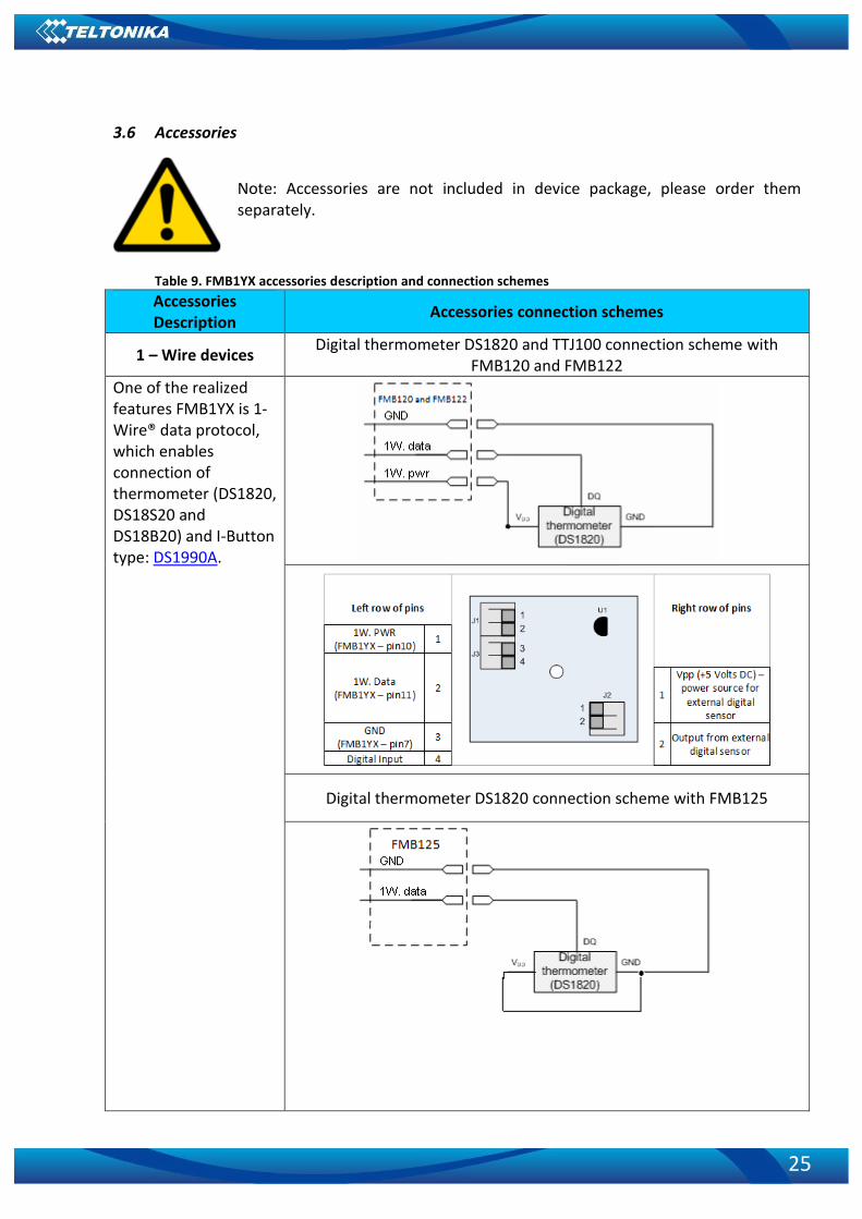
3.6 Accessories
Note: Accessories are not included in device package, please order them separately.
Table 9. FMB1YX accessories description and connection schemes
Accessories Description
Accessories connection schemes
1 – Wire devices Digital thermometer DS1820 and TTJ100 connection scheme with
FMB120 and FMB122
One of the realized features FMB1YX is 1-Wire® data protocol, which enables connection of thermometer (DS1820, DS18S20 and DS18B20) and I-Button type: DS1990A.
Digital thermometer DS1820 connection scheme with FMB125

26
Accessories Description
Accessories connection schemes
I-Button DS1990A connection scheme
Fuel Tank sensors Fuel sensor scheme
A fuel tank level sensor exists in most cars, which shows the approximate fuel level in the driver’s indicator panel. It is possible to connect FMB1YX Analog input to it (if sensor returns analogue signal proportional to fuel level). After the connection to the tank fuel level sensor, calibration is needed. Calibration is needed because most fuel tank sensors are not linear. Calibration is performed by measuring voltage dependence on volume of fuel in tank.
Alarm buttons, door sensors, etc.
Panic button connection

27
Accessories Description
Accessories connection schemes
Alarm buttons, door sensors, ignition, etc. return two states: high or low voltage. FMB1YX Digital inputs are used to read this information.
In cases when sensor FMB1YX output signal is negative, an additional relay has to be installed to convert negative signal to positive.
Inverting relay connection
Immobilizer relay Immobilizer relay connection
When connected as shown below, FMB1YX disables engine starter when output is ON. More details about relays can be found below.
Relays Automotive relay pinout

28
Accessories Description
Accessories connection schemes
An ordinary automotive relay is used to invert input signal or to immobilize engine starter. Note, that they are available as 12 V or 24 V.
3.7 Navigate LED
Table 10. FMB1YX navigation LED description
3.8 Status LED
Table 11. FMB1YX status LED description
Behavior Meaning Blinking every second Normal mode
Blinking every 2 seconds Sleep mode
Blinking fast for a short time Modem activity
Off Device is not working Or Boot mode
4 OPERATIONAL BASICS
4.1 Operational principals
FMB1YX module is designed to acquire records and send them to the server. Records contain GNSS data and I/O information. Module uses GNSS receiver to acquire GNSS data and is powered with three data acquiring methods: time-based, distance-based and angle-based. Note, that if FMB1YX loses connection to GNSS satellites, it continues to make records, however
Behavior Meaning Permanently switched on GNSS signal is not received
Blinking every second Normal mode, GNSS is working
Off GNSS is turned off because: Device is not working Or Sleep mode
Blinking fast constantly Device firmware being flashed
29
coordinate in these records remains the same (last known coordinate). All data is stored in flash memory and later can be sent via GPRS.
GPRS and SMS settings are described in later sections. FMB1YX communicates with server using special data protocol.
FMB1YX can be managed by SMS commands. SMS Command list is described in SMS/GPRS COMMAND LIST section. Module configuration can be performed only via SMS.
4.2 Sleep modes
There are three sleep modes: GPS sleep, Deep sleep and Online sleep mode.
4.2.1 GPS Sleep mode
FMB1YX is able to go to GPS sleep mode if such mode is enabled. Sleep mode timeout (defined period in minutes) starts counting when device is in STOP
mode. After timeout is reached and all conditions for GPS sleep mode are met, device goes to sleep mode. While in GPS sleep mode, FMB1YX turns GPS module off and it is still making new periodic records. As a result power usage decreases, in turn saving vehicle battery.
FMB1YX can enter GPS sleep mode if ALL of these conditions are met:
• FMB1YX has to be configured to work in GPS Sleep mode and start sleep timeout is reached;
• Device must be synchronized time with GNSS satellites and have GPS fix;
• No movement by configured movement source or movement sensor is detected;
• Ignition (configured Ignition Source) is off.
• Forced wakeup is not set;
• Have no SMS to read; FMB1YX exits GPS sleep mode when if ONE of following conditions are true:
• Movement by movement source or movement sensor is detected;
• Ignition (configured Ignition Source) is turned on.
4.2.2 Deep Sleep mode
While in deep sleep mode, FMB1YX sets GNSS receiver to sleep mode and turns off GSM/GPRS module (it is not possible to wake up device via SMS). Despite records with last known coordinate are being saved and send to AVL server (GSM/GPRS module is turned on to send data and after that it is turned off again), power usage is decreased to save vehicle’s battery. Note, that power saving depends on two configurable parameters: send period and min. record saving period in “X on Stop Mode”. When records are sendet in deep sleep mode, after successful records sending open link timeout counter will be sciped and FMB1YX will enter deep sleep mode immediately.
Because a lot off functions are disabled in deep sleep mode 13 I/O elements are disabled from records that are generated in this mode: GSM Signal, GNSS Status, GNSS PDOP, GNSS HDOP, Speed, GSM CellID, GSM Area Code, Fuel rate GPS, Active GSM Operator, Trip Odometer, Total Odometer, Fuel Used GPS and ICCID.
FMB1YX can enter deep sleep mode if ALL of these conditions are met:
• FMB1YX has to be configured in Deep Sleep Mode and Sleep timeout is reached
• Device must be synchronized time with GNSS satellites and have GPS fix;

30
• Ignition (configured Ignition Source) is off.
• Movement by accelerometer or configured movement source is not detected;
• Min. Record Saving Period (Data Acquisition Mode settings) must be bigger than Open Link Timeout parameter, that FMB1YX could close GPRS link.
• Send period (Data Acquisition Mode settings) minus Open Link Timeout must be more than 90 sec., that FMB1YX could close GPRS link for at least 90 sec.
• Forced wakeup is not set;
• Have no SMS to read;
• Data socket(s) are close;
• Data sending is not in progress;
• FOTA is not in progress; FMB1YX exits deep sleep mode when if ONE of following conditions are true:
• Movement by accelerometer or configured movement source is detected;
• Ignition (configured Ignition Source) is turned on.
4.2.3 Online Deep Sleep mode
In this mode device works as in Deep Sleep mode, but without deregistering from GSM network. GSM part stays powered, so this increases power consumption. In this mode, device should receive/send SMS and make/receive calls. Also not closes GPRS context, if previously opened.
Conditions to enter Online Sleep mode is the same as entering Deep Sleep mode. FMB1YX exits Online Sleep mode when if ONE of following conditions are true:
• Movement by accelerometer or configured movement source is detected;
• Ignition (configured Ignition Source) is turned on.
4.3 Virtual odometer
Virtual odometer is used to calculate traveled distance in FMB1YX as separate I/O elements. When FMB1YX detects movement, it starts counting distance using GNSS signal: every second it checks current location and calculates distance between current and previous point. It keeps adding these intervals until it is time to make a record, then FMB1YX records its location and adds odometer value, which is equal to the sum of all distances, measured every second. The are two odometers I/O elements: Total odometer and Trip odometer.
Total odometer counts all distance traveled by vehicle. After device restart the value in this I/O element will not be erased. Total odometer value can be changed by SMS command “odoset” (SMS Command list is described in SMS/GPRS COMMAND LIST section).
Trip odometer is Trip scenario element and it can be selected from two modes: Continuous and Between Records. Both modes requires ignition (configured ignition source) to be turned on.
When Between Records mode is selected, when record is made, odometer resets to zero and distance calculation starts all over again.
When Continuous odometer mode is selected, all distance calculations is counted from records and sums them to one distance. Continuous odometer stops counting, when vehicle is at stop and ignition is turned off.

31
Figure 8 Odometer continuous and Not continuous distance counting parameter example
4.4 Features
Using available features can greatly increase FMB1YX usability options.
4.4.1 ECO driving/Green driving Scenarios
ECO driving/Green driving Scenarios. Helps to prevent and inspect driver about harsh driving. Eco driving scenario continuously monitors: accelerating, braking and cornering forces depending on build in accelerometer or Green driving depending on GPS. The device inspects driver if needed. Monitoring sensitivity is configurable.
Digital output can be controlled by scenario for user needs, buzzer or LED for example. Output activation time after harsh event is also configurable.
To save GPRS traffic ECO driving/Green driving event will be generated (included into records) only when FMB1YX measured values are higher than those set in configuration, without additional I/O settings.
To prevent generating false events, harsh acceleration and harsh braking is monitored only when following conditions are fulfilled:
Ignition is ON (configured Ignition Source)
Vehicle speed is equal or higher than 10km/h
Harsh cornering is monitored only when following conditions are fulfilled:
• Ignition is ON (configured Ignition Source)
• Vehicle speed is equal or higher than 30km/h
ECO driving or Green driving Scenario? Eco driving is based on accelerometer value and Green driving based on GPS position.

32
PLEASE NOTE that Eco Driving functionality generally is dependent on accelerometer. Auto calibration must be done before using ECO driving scenario. All information about auto calibration descrybed in 5.9.1.2 chapter.
4.4.2 OverSpeeding Scenario.
Helps to prevent from exceeding fixed speed and inspects driver if needed. Digital output can be controlled by scenario for user needs, to manage buzzer, LED, etc.
4.4.3 Jamming detection
Jamming detection shows when GSM signal jamming occurs. Digital output can be controlled by scenario for user needs, to manage buzzer, LED, etc.
4.4.4 Trip
Trip customizable feature enables user extended monitoring of performed trips (from engine start at present location to engine stop at arrived location), log their start and stop points, view driven total distance1 and calculate eco score value.
Odometer calculation source can be selected between GNSS, OBD or LVCAN.
Note: Scenarios and Trip feature are activated (DOUTs are activated) only if ignition is on.
4.4.5 DOUT Control Via Call
Activates DOUT on incoming call
Note: in Excessive Idling, Jamming and Trip scenarios if Eventual Records is enabled Event will be generated (included into send records) only when scenario starts and finishes. If Eventual Records is disabled scenario status value is sent in each AVL record.
4.4.6 Immobilizer
Immobilizer Scenario. Vehicle can be used only if iButton is connected. If iButton List Check is enabled gives ability to use vehicle only for 500 specific iButton owners (specified in iButton list). If iButton List Check is disabled connect any iButton to pass Immobilizer security. Digital output can be controlled by scenario for user needs, to manage buzzer, LED, etc.
1 Continuous trip odometer – total driven distance, works only in TRIP mode. Continues distance is
counted only for ONE trip. If trip is finnished (stop point is detected), odometer resets to 0 (zero). Next trip will start counting from the begining. Betwen Records trip odometer – another odometer that are used only in TRIP mode. In this mode distance will be counted until any record is made, then odometer will be reseted to zero and started counting to next record again.

33
4.4.7 iButton read notification
This functionality allows user to see when iButton is being readed. Selected DOUT turns on for configured duration.
4.4.8 GPS Fuel Counter
This functionality is meant to calculate fuel consumption based on set consumption values in different situations.
4.5 Accelerometer Features
4.5.1 Excessive Idling
Informs you if your vehicle is stationary but engine is on for selected period of time to help you to save fuel.
4.5.2 Unplug Detection
Unplug detection scenario generates event when FMB1YX is unplugged from external power and plugged into external power.
4.5.3 Towing Detection
Towing detection feature helps to inform driver about car deporting. FMB1YX generates event when car is being towed or lifted, for example in case of vehicle evacuation.
4.5.4 Crash Detection
If Crash detection is enabled, it monitors acceleration on each axis, which helps to detect an accident.
If Crash trace is disabled crash detection event will be generated (included into send record) only when scenario starts and finishes.
If Crash trace is enabled FMB1YX will collect acceleration data every 40 msec. Buffer is big enough to hold data for 5 seconds and on Crash Event detection, records will be generated from this buffer, following these conditions:
• Every second Acceleration changed more then > 50mG Data will be collected and records generated 5 seconds after the event using the same conditions.
• Every generated record will have accelerometer X Y Z values included.
• Each record will have accurate timestamps in milliseconds.
Note: in Unplug Detection and Towing Detection scenarios if Eventual Records is enabled Event will be generated (included into send records) only when scenario starts and finishes. If Eventual Records is disabled scenario status value is sent in each AVL record.
4.6 Bluetooth
Bluetooth can work in two modes - slave or master. While working as master mode - Bluetooth can connect to defined "hands free" or "OBDII"
system.

34
While working as slave mode - Bluetooth can accept incoming connection from external device.
NOTE: FMB1YX supports ONE connection at a time.
4.7 Auto Geofence
Auto Geofencing feature if enabled is activated automatically by turning off car ignition. Next time before driving user has to disable Auto Geofencing with iButton, digital input, by external voltage or by car Engine RPM. In case of theft car leaves Auto Geofencing zone without authorization FMB1YX device automatically sends record to AVL application and SMS (if configurated).
4.8 Manual Geofence
Geofencing is another feature which is highly customizable and can detect wherever car enters or leaves customized areas. More about Geofencing can be read in 5.13 chapter.
4.9 iButton list
iButton list is used to enter authorized iButton ID codes, which are used to authenticate driver in Authorized driving and Auto Geofencing options.
5 CONFIGURATION
5.1 Configurator
FMB1YX module has default factory settings. Settings should be changed according to your application and your GSM operator information.
FMB1YX configuration may be performed via SMS commands or configurator. FMB1YX has one user editable profile. It can be configured to acquire and send data to server. If device is not able to send data to
server, GSM is not available FMB1YX will start storing records to flash memory. It is possible to store up to 192 000 data records with 128 Mb SD memory card (when 100 Mb are used for store records). It will send data later when GPRS is available again. Note that FMB1YX can have memory full of records. In such case it will start deleting oldest records in order to save new ones. Sending all data records to server may take some time.
FMB1YX configuration is performed via FMB1YX Configurator program. Contact sales manager to get the latest FMB1YX Configurator version. FMB1YX configurator operates on Microsoft Windows OS and uses MS .NET Framework. For Windows XP you will need MS .NET Framework 4 (with MS .NET Framework 4 update KB2468871-v2) for Windows Vista, Windows 7, Windows 8.1, Windows 10 MS .NET Framework 4.6.2 or later. Please ensure that suitable MS .NET Framework version for your OS is installed on your PC before starting configurator. Latest MS .Net Framework version can be downloaded from official Microsoft web page.
Module configuration is performed over USB cable or Bluetooth port. Configuration process starts from starting FMB1YX Configurator program and then connecting to FMB1YX

35
device via Connect button located in Online menu part. FMB1YX has one user editable profile, which can be loaded from device, and saved. User can also revert to default settings, by pressing Reset to defaults button. After any modification of configuration settings it has to be saved to FMB1YX device, otherwise it will not be written to device.
Figure 9 FMB1YX configurator window when selecting the connection method
Figure 10 FMB1YX configurator main window when connected to it and successfully loaded parameters
Figure 11 FMB1YX configurator status column

36
5.1.1 Main Buttons description:
‘Connect to device’ (Figure 9) – connects device. ‘Load from device – loads configuration from device. ‘Save to device’ – save configuration to device. ‘Load from file’ – load configuration from file. ‘Save to file’ – save configuration to file. ‘Update firmware’ – update firmware on device. ‘Reset device’ – reset device configuration to default.
5.1.2 Keyword SMS (GPRS) commands:
"setkey <oldkeyword> <newkeyword>" - Set new or change the keyword. Configuration should be not locked. Example:
New keyword (set): <name>{space}<pass>{space}setkey{space}{space}<newkeyword>
Change keyword (change): <name>{space}<pass>{space}setkey{space}<oldkeyword>{space}<newkeyword>
"delkey <keyword>" - Deletes current keyword. Configuration keyword should be configured and not locked.
Example: <name>{space}<pass>{space}delkey{space}<keyword>
5.1.3 Keyword configuration with TCP
If configuration has keyword, it will be saved to configuration file. After TCP configuration: if keyword in configuration file does not match keyword in device,
configurator will ask which keyword must be used for device. If device is locked, keyword cannot be changed with TCP configuration.
5.2 Status info
Status info monitoring FMB1YX real time information in 5 different positions: Device info, GNSS info, GSM info, OBD/ CAN adapter info and I/O info. All this information can be saved into .HTML format with a button whitch is in device info table top right corner.
In device info user can see device name, firmware version, last device start time, RTC Time, power voltage (mV), device IMEI, SD card free space, Device uptime, Battery voltage (mV) and internal battery status.
In GNSS info user can see: ▪ Real time GNSS status information: module status (ON, deep/GPS/Online sleep mode),
how much GNSS packets device got from startup, what is fix status and what was last GNSS fix time.
▪ Satellites information: how many and what type of satellites are visible. How many satellites are used for location positioning.
▪ Location information: latitude, longitude, altitude, angle, HDOP, PDOP and speed. In GSM Info user can see:

37
▪ GSM status: modem status, SIM status, GPRS status, actual operator code and GSM signal level.
▪ GPRS traffic: how much data has been send from device and received from device. ▪ Sockets information: what server domain and port is used. ▪ Records: how much records were sended to server from last data reset, when last record
send to server was and when was last server response. ▪ SMS count: how much FMB1YX received SMS and how much SMS was send from device.
In OBD info user can see main information from OBD (if device connected to vehicle with OBD II Bluetooth dongle adapter): vehicle VIN code and used OBD protocol.
In CAN Adapter info user can see main information from LV-CAN200/ ALL-CAN300 (if device connected to LV-CAN200/ ALL-CAN300): program number and LV-CAN200/ ALL-CAN300 SW version
In I/O info user can see all I/O element values from all configurable I/O elements.
5.3 Security info
In security section user can see SIM card and configurator keyword security information. ▪ User can see SIM1 and SIM2 state and now connected to device SIM card current
status. If used SIM card with PIN code user can enter it here. How much attempts left to enter pin code is showed to.
▪ When SIM PIN code is entered correctly user can change PIN code or disable it from SIM card. When SIM PIN is disabled and user what to enable it again user must enter last used PIN code.
▪ If into device are inserted two SIM cards, user can change PIN code to both of them. ▪ For configuration security keyword can be set to configurator. Keyword can be
saved in configuration file (.cfg), so there is no need to connect the device to the configurator to configure keyword. Min keyword length is 4 symbols and max length is 10 symbols. Only uppercase and lowercase letters and numbers are supported. Keyword can be configured to .cfg configuration file when device is not connected to device.
5.4 System settings
System settings have 9 configurable parameters:
• Sleep settings, where user can choose sleep mode;
• Ignition source, where user can choose between power voltage, digital input 1, accelerometer and engine RPM as ignition sources. More than one ignition source can be selected at the same moment. User can select movement start and movement stop delay time (in seconds): those parameters are used when ignition source is accelerometer. Into ignition status take the following functionalities: power manager, eco driving, excessive idling, fuel consumption, over speeding, towing and trip functionalities.
• Object Motion Detection Settings, where user can configure 4 ways how FMB1YX will detect stopped movement, and change its working mode (for working modes, read section 5.8). Other functionalities that depend from movement source: power manager, fuel consumption and trip.
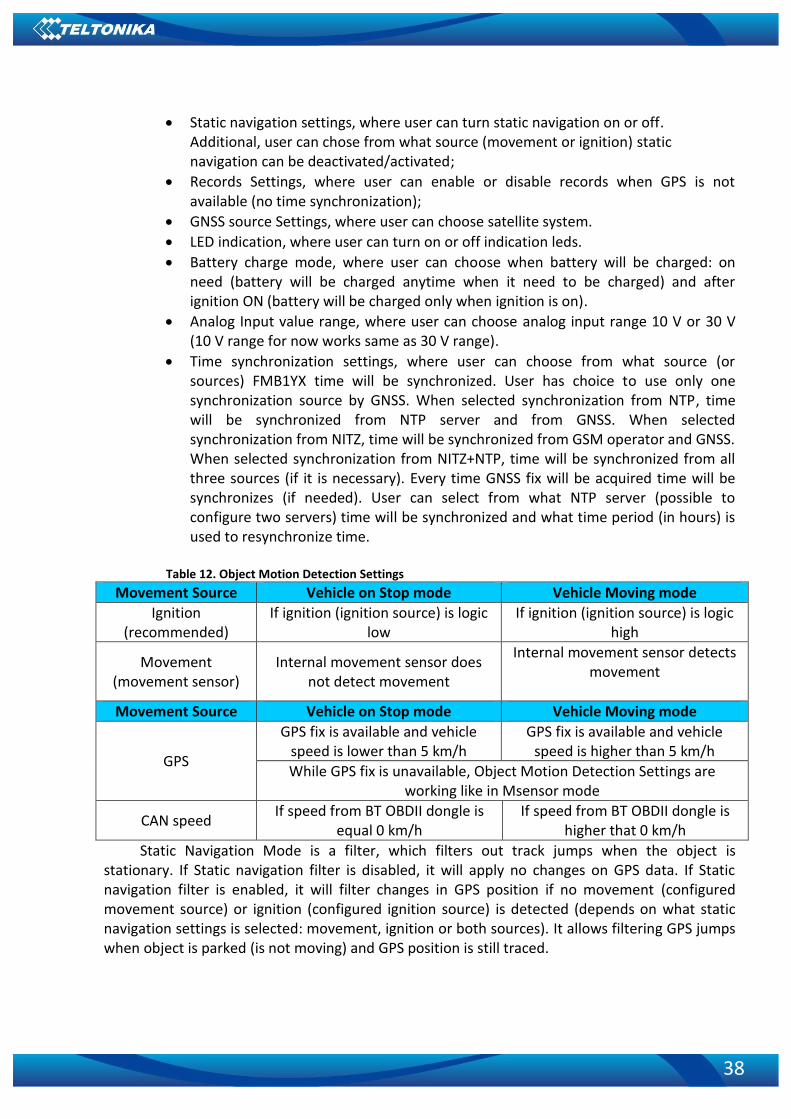
38
• Static navigation settings, where user can turn static navigation on or off. Additional, user can chose from what source (movement or ignition) static navigation can be deactivated/activated;
• Records Settings, where user can enable or disable records when GPS is not available (no time synchronization);
• GNSS source Settings, where user can choose satellite system.
• LED indication, where user can turn on or off indication leds.
• Battery charge mode, where user can choose when battery will be charged: on need (battery will be charged anytime when it need to be charged) and after ignition ON (battery will be charged only when ignition is on).
• Analog Input value range, where user can choose analog input range 10 V or 30 V (10 V range for now works same as 30 V range).
• Time synchronization settings, where user can choose from what source (or sources) FMB1YX time will be synchronized. User has choice to use only one synchronization source by GNSS. When selected synchronization from NTP, time will be synchronized from NTP server and from GNSS. When selected synchronization from NITZ, time will be synchronized from GSM operator and GNSS. When selected synchronization from NITZ+NTP, time will be synchronized from all three sources (if it is necessary). Every time GNSS fix will be acquired time will be synchronizes (if needed). User can select from what NTP server (possible to configure two servers) time will be synchronized and what time period (in hours) is used to resynchronize time.
Table 12. Object Motion Detection Settings
Movement Source Vehicle on Stop mode Vehicle Moving mode
Ignition (recommended)
If ignition (ignition source) is logic low
If ignition (ignition source) is logic high
Movement (movement sensor)
Internal movement sensor does not detect movement
Internal movement sensor detects movement
Movement Source Vehicle on Stop mode Vehicle Moving mode
GPS
GPS fix is available and vehicle speed is lower than 5 km/h
GPS fix is available and vehicle speed is higher than 5 km/h
While GPS fix is unavailable, Object Motion Detection Settings are working like in Msensor mode
CAN speed If speed from BT OBDII dongle is
equal 0 km/h If speed from BT OBDII dongle is
higher that 0 km/h
Static Navigation Mode is a filter, which filters out track jumps when the object is stationary. If Static navigation filter is disabled, it will apply no changes on GPS data. If Static navigation filter is enabled, it will filter changes in GPS position if no movement (configured movement source) or ignition (configured ignition source) is detected (depends on what static navigation settings is selected: movement, ignition or both sources). It allows filtering GPS jumps when object is parked (is not moving) and GPS position is still traced.

39
Figure 12 System settings configuration
In GNSS source Settings user can configure which GNSS system or systems to use. User has choice to use only one system of GPS, Glonass, Galileo or Beidou. Also it is able
to choose two or three systems together. One exception is that you can not combine Beidou and Glonass systems together.
List of configurable GNSS sources: Beidou only ID:01 Glonass only ID:02 Galileo only ID:04 Galileo+Beidou ID:05 Galileo+Glonass ID:06 Example of good configuration GPS only ID:08 GPS+Beidou ID:09 GPS+Glonass ID:10 GPS+Galileo ID:12 GPS+Galileo+Beidou ID:13 GPS+Galileo+Glonass ID:14 List of NON–configurable GNSS sources: Glonass+Beidou Galileo+Glonass+Beidou GPS+Glonass+Beidou GPS+Galileo+Glonass+Beidou Example of bad configuration

40
5.5 GPRS
‘GPRS’ defines main parameters for FMB1YX: GSM operator APN and GPRS username and password (optional – depending on operator), destination server IP and port, and allows to set protocol used for data transfers – TCP or UDP. SIM1 and SIM2 GPRS settings can be configured separate. Also all server setting and backup server mode can be selected for backup server configuration.
Backup server has 3 different modes: ▪ Disable: backup server is not used. ▪ Backup: send to backup server if main server not available (Failed to open Link) or,
main server response timeout is detected 5 times in row. ▪ Duplicate: send records to both servers (main and backup), delete record from sd
card (or RAMS) only if both servers accepted records. Some operators use specific authentication for GPRS session – CHAP or PAP. If any of these
is used, APN should be entered as ‘chap:<APN>’ or ‘pap:<APN>’. I.e. if operator is using APN ‘internet’ with CHAP authentication, it should be entered as ‘chap:internet’. Information about APN and authentication type should be provided by your GSM operator.
Records settings. Here user can modify if FMB1YX device will send newest records first, meaning, that the most important thing is to know recent position of car, older records are being sent right after newest records arrive to AVL application.
Activate Data Link Timeout is used to set timeout of link between FMB1YX and AVL application termination. If FMB1YX has already sent all records it waits for new records before closing link (except Deep Sleep mode, more indoemation in Deep Sleep mode chapter). If new records are generated in the period of this timeout, and minimum count to send is reached, they are sent to AVL application. This option is useful when GSM operator charge for link activation.
Server Response Timeout is used to set time period waiting for response from server side. FOTA WEB settings are used for FOTA WEB server connection parameters configuration.
Status enables or disables FOTA WEB funkcionality. In domain and port user can enter address and port number of FOTA website. Period is used fot timeout of reapeating connection to FOTA WEB server.
Figure 13 GPRS configuration

41
5.6 SMS/Call Settings
Essential fields in ‘SMS’ part is ‘Login’ and ‘Password’. The login and password are used with every SMS sent to FMB1YX. If login and password are not set, in every SMS sent to FMB1YX device two spaces before command have to be used (<space><space><command>).
Command structure with set login and password: <login><space><password><space><command>, example: “asd 123 getgps” Phone numbers have to be written in international standard, with using “+” or without
using it (in both cases number will be recognized, but when number is without “+” symbol, it will not generate IDD Prefix, which depends on location of phone). If no numbers are entered, configuration and sending commands over SMS are allowed from all GSM numbers.
SMS data sending settings allows or does not allow sending AVL data using binary SMS. AVL data will be send by SMS only when there are no GPRS connection. This setting does not affect replies to SMS request messages – answers are always sent back to sender telephone number.
Figure 14 SMS \ call Settings configuration
Incoming Call Settings
This parameter defines device action during incoming call:
• Do Nothing
• Hang up – automatically hang up incoming call
• Report Position – Report position to calling number via SMS
• Auto Answer (HF) – Auto answer incoming call if hands free device is connected. If
hands free device is not connected, then incoming call will be hanged up.
Hands free call functionality When FMB1YX is connected to hands free headset it can call to user defined GSM
numbers.

42
Figure 15 Hands Free Call Settings configuration for FMB120 and FMB1221
Outgoing Call Trigger parameter determines which event will triggers call. FMB125
supports first for different call triggers and FMB120/FMB122 supports all eight call triggers:
• None selected – disables call trigger functionality.
• DIN1 – first digital input event triggers call to user selected GSM number.
• Crash Event – crash event triggers call to user selected GSM number.
• DIN1 and Crash Event – both events triggers call to user selected GSM number.
• DIN2 – seconf digital input event triggers call to user selected GSM number.
• DIN1 and DIN2 Event – both events triggers call to user selected GSM number.
• DIN2 and Crash Event – both events triggers call to user selected GSM number.
• DIN1, DIN2 and Crash Event – all events triggers call to user selected GSM
number.
SMS Event Time Zones FMB1XX works with synchronized GPS time which is UTC+0, with this option customer can
configurate his time zone and get SMS with correct time.
Note: Please do not set Data Send Number to some cell phone number, because it will not understand binary SMS. When sending a binary SMS to a phone number, which is a server phone number, the server can interpret and understand binary code, so the data can be read and you can view it on the server.
SMS login and password and authorized number list are used to protect FMB1YX module from unauthorized access. Module accepts messages only from a list of authorized numbers and with proper module login and password. Phone numbers have to be written in international standard, with using “+” or without using it (in both cases number will be recognized). If no authorized numbers are entered, module accepts messages from all numbers.
1 FMB125 don’t have DIN2 selection

43
5.7 GSM Operators, SIM1 Roaming and SIM2 Roaming/ Home Operator list, Blacklist Operator list
Operators list – FMB1YX can work in different modes (use different settings) according to the operator list defined. Operator list is used for Data Acquisition Mode switching (see Data Acquisition Mode settings chapter for more details). Modes are changed based on GSM operator FMB1YX is connected to.
Figure 16 SIM1 Roaming, SIM2 Roaming/ home Operators and Operator BlackList configuration
If roaming operator list is left empty, FMB1YX will automatically detect home operator. If
home operator will be written to roaming operator list any part, it will be detected as home operator, not roaming. Any not written operator in roaming operator list (not home operator) will be recognized as unknown operator and FMB1YX will work in Unknown mode (make sure it is configured to allow data sending – GPRS context is enabled).
Operator Blacklist - if user wants that FMB1YX do not connect and work with a particular operator it must be written to Operator BlackList. Total 50 operators can be written to this list.
Operator Blacklist working: operator search procedure is initiated as normal every 15 minutes and tries to connect to an operator with the strongest signal. It will prioritize operators which are specified in the operator list. If no operators from the operator list are available, the device will try to connect to an operator from the blacklist. If device connects to operator from black list – best operator search procedure is initiated instantly. During the time when device is connected to Black list operator - no GPRS connection would be initiated and no data would be send via GPRS. The ability to send SMS commands to the device remains. If no suitable operator is found on both lists, the device will try to connect to a remaining available operator with the strongest signal.
In SIM2 Roaming/ Home Operator list home operator must be added to the any part of the list that functionality works correctly.

44
Current operator is in
black operator list
Opening GPRS
Do not allow to
open GPRS/Send
data
A
Work as usual
A
YES
NOWhite List empty
Best operator
search
A
YES
NOBlack List empty
YES
Skip op search
procedure
NO
Find new best
operator from
White List
A
YES
Connect to
strongest signal
exept if in Black
list
A
Figure 17 Operator search functionality diagram. White list is SIM1 Roaming and SIM2 Roaming/ Home Operator lists.
5.7.1 Dual SIM
FMB1YX have possibility to have inserted in them two SIM cards. GPRS settings and Roaming Operators can be configurd separate for SIM1 and SIM2. In SIM2 Roaming/ Home operator list home operator must be added to the any part of the list that functionality works correctly. Dual SIM operator search functionality works like that: SIM1 and SIM2 home operators have highest priority: When device is connected to home operator - manual roaming operator search is disabled. When device is disconnected from home operator - operator search procedure is initiated as normal every 15 minutes. SIM1 Roaming operators list has higher priority then SIM2 Roaming Operator list. When device finds new operator from SIM1/SIM2 lists – it switches to new SIM according to list and connects to new operator.

45
Figure 18 Dual SIM functionality diagram.

46
5.8 Data Acquisition Mode settings
Data Acquisition Modes are an essential part of FMB1YX device, it is also highly configurable.
By configuration user defines how records will be saved and sent. There are three different modes: Home, Roaming and Unknown. All these modes with configured data acquisition and send frequencies depend on current GSM Operator defined in Operator list (see chapter GSM Operators, Roaming and Blacklist Operator list) and are switched when GSM operator changes (e.g. vehicle passes through country boarder).
If current GSM operator is defined as Home Operator, device will work in Home Data Acquisition mode, if current operator is defined as Roaming Operator, device will work in Roaming Data Acquisition mode, and if current operator code is not written in Roaming Operator list, device will work in Unknown Acquisition mode.
This functionality allows having different AVL records acquire and send parameters values when object is moving or stands still. Vehicle moving or stop state is defined by Stop Detection Source parameter. There are 4 ways for FMB1YX to switch between Vehicle on Stop and Vehicle Moving modes, see section 5.4 , Table 12. Object Motion Detection Settings.
FMB1YX has 6 different modes. Operational logic is shown in Figure 19.
Figure 19 Data Acquisition Mode operational logic
If home operator will be written to roaming operator list any part, it will be detected as home operator, not roaming.

47
Operator search is performed every 15 minutes. Depending on current GSM operator, Home, Roaming or Unknown mode can be changed faster than every 15 minutes. This process is separate from operator search. Movement criteria are checked every second.
Figure 20 Data Acquisition Mode configuration
‘Min Saved Records’ defines minimum number of coordinates and I/O data that should be
transferred with one connection to server. If FMB1YX does not have enough coordinates to send to server, it will check again after time interval defined in ‘Sending Period’.
Send period – GPRS data sending to server period. Module makes attempts to send
collected data to server every defined period. If it does not have enough records (depends on parameter Min. Saved Records described above), it tries again after defined time interval.
Note: Keep in mind that FMB1YX operates in GMT:0 time zone, without daylight saving.
FMB1YX is able to collect records using four methods at the same time: time, distance,
angle and speed based data acquisition: Time based data acquiring (Min. period) – records are being acquired every time when defined interval of time passes. Entering zero disables data acquisition depending on time.

48
Min. time period
Distance based data acquiring (Min. distance) – records are being acquired when the distance between previous coordinate and current position is greater than defined parameter value. Entering zero disables data acquisition depending on distance.
Min. distance
Angle based data acquiring (Min. angle) – records are being acquired when angle difference between last recorded coordinate and current position is greater than defined value. Entering zero disables data acquisition depending on angle.
Min. angle
Speed based data acquiring (Min. Speed Delta) – records are being acquired when speed difference between last recorded coordinate and current position is greater than defined value. Entering zero disables data acquisition depending on speed.
5.9 Features settings
In Features window five different scenarios and GPS fuel counter are available.

49
Figure 21 Scenarios configuration
5.9.1 Green Driving
When vehicle exceeds on of Max Acceleration, Max Braking or Max Cornering parameters value, scenario is activated, record will be generated and digital output status will be changed to 1 (if configured). You can configure all three parameters in m/s2 (meter per second squered) units. Scenario is activated until current Acceleration, Braking or Cornering value decreases below parameter value.
Parameters used with Green Driving functionality.
Figure 22 Green Driving configuration parameters for FMB120 and FMB1221
1 FMB125 don’t have DOUT 2 selection

50
Table 13. Green driving parameters description
Green driving configuration
parameter name Description
Scenario settings Enable/Disable Green driving functionality.
Max Acceleration Force Value which can be reached while accelerating without triggering harsh acceleration event.
Max Braking Force Value which can be reached while braking without triggering harsh braking event.
Max Cornering Force Value which can be reached while cornering without triggering harsh cornering event.
Source From what source (GPS or accelerometer) data will be collected.
5.9.1.1 Data output
Green driving functionality generates events on three cases. If vehicles:
• Acceleration exceeds defined parameter value
• Deceleration (braking) exceeds defined value
• Cornering force exceeds defined value Program continously monitors and process data from accelerometer/GPS than decides whether harsh event is detected or not. If any of three cases are satisfied event is generated. Record is saved and sent to server (FMB1YX must be configured properly). Event value is multiplied by 10 before sending/saving record to get more precision when displaying data*.
Digital output 1 or digital output 2 can be activated for a period of time to warn driver. Output on-time should/can be configured separately for each feature case.
*Example. If acceleration harsh event of 3.55 m/s2 detected. Record with value 3.55*10 = 35.5 ≈ 36 will be saved ant sent to server.
5.9.1.2 Auto Calibaration 1. Vehicle stopped 2. Road is straight 3. Send SMS "auto_calibrate" 4. Accelerate to > 30 km/h for 5 sec. 5. FMB will send response when calibration is success. Calibration is saved to Internal Flash, after restart should be the same To check autocalibration status send: position_info To zero out accelerometer axis SMS: "calibrate", can be used, vehicle speed must be 0 km/h.

51
5.9.2 Over Speeding
When vecicle speed exeeds configured max speed value scenario is activated, record will be generated and digital output status will be changed to 1 (if configured).
Scenario is activated until current speed decreases below parameter value.
Figure 23 Over Speeding configuration parameters for FMB120 and FMB1221
5.9.3 Jamming
When jamming is detected scenario is activated, record will be generated and digital output status will be changed to 1 (if configured).
Jamming timeout time can be configures. After Jamming trigger count configured timeout (in seconds), digital output control and jamming event will be generated after this timeout. If Jamming ends during timeout counting no event will be generated and output will not be controlled.
You can configure eventual records parameter: when he is disabled scenario status value will be appeared in each AVL record, and when he is enabled scenario status value will be appended only to eventual records.
Figure 24 Jamming configuration parameters for FMB120 and FMB1222
1 FMB125 don’t have DOUT 2 selection 2 FMB125 don’t have DOUT 2 selection

52
5.9.4 Use authorized numbers to control DOUT via call
Scenario is activated and digital output is ON, when call is received from number which is in authorized numbers list.
Figure 25 DOUT control via call configuration parameters for FMB120 and FMB1221
Call control functionality2: ▪ When FMB1YX is configured to control DOUT1/DOUT2 device waits incoming call
from configured secure number. If call is received FMB1YX turns on DOUT1/DOUT2 for user defined Duration timeout (s). If Duration timeout set to „0“(s), DOUT1/DOUT2 will be OFF.
▪ DOUT1/ DOUT2 can be turned off by Duration timeout (s) or by digital input 1, digital input 2 or digital input 3 (DOUT deactivation settings).
▪ DOUT1/DOUT2 can be turned off before Duration timeout (s) by selected DIN (DOUT deactivation settings).
▪ DOUT1/DOUT2 always will be ON, if DOUT deactivation set to DIN1 for example, but DIN1 will be never turned ON or set Duration timeout to Max value (2147483647) it is about 68 years.
5.9.5 Immobilizer
If Dout Control is disabled, scenario will only generate events without digital output activation. If Dout Control is enabled DOUT1/DOUT2 (optional) turns ON if Ignition turns ON (configured Ignition Source =1). After iButton ID is read (any iButton is attached), DOUT1/DOUT2 turns OFF. After iButton identification, Ignition (configured Ignition Source) can be turned OFF (configured Ignition Source =0) for no longer than 30 seconds3, otherwise immobilizer must be
1 FMB125 don’t have DOUT 2, DIN 2 and DIN 3 selection 2 FMB125 don’t have DOUT 2, DIN 2 and DIN 3 selection 3 FMB125 don’t have DOUT 2 selection
Figure 26 Immobilizer configuration parameters for FMB120 and FMB1223

53
repeated. If iButton list checking parameter is enabled, authorization will be successful only if attached iButton is specified in the iButton list.
5.9.6 iButton read notification
This functionality allows user to see when iButton is being readed. Selected DOUT1 turns on for configured duration, after DOUT ON duration ends configured DOUT don’t turns on, even if iButton is left attached.
Figure 27 iButton read notificatoin configuration parameters for FMB120 and FMB1221
5.9.7 GPS Fuel Counter
Configuration of Fuel Consumption
1. To configure this parameters use fuel consumption norm which are presented in your car technical documentation. By default speeds for this fuel consumption norms are: City – 30 km/h, Average - 60km/h, Highway - 90 km/h. If you want, you can change it.
2. When speed are higher than highway fuel consumption speed, we add for highway fuel consumption x % of highway fuel consumption every y km/h, by default FMB1YX add 20% every 50 km/h. It means that fuel consumption is (1.2 * Highway Fuel Consumption) on 140 km/h speed, (1.4 * Highway Fuel Consumption) on 190 km/h speed.
3. Correction coefficient is use for correction every value of fuel consumption which is send to server (Used Fuel * Correction coefficient). By default it is 1, min 0.01 and max 2. For example when correction coefficient is 1 and FMB1YX calculate that used fuel of 35 m distance is 20 ml, to server will be sent value: 20 ml, if correction coefficient is 1.2 to server will be sent value: 20 * 1.2 = 24 ml.
4. Fuel consumption on idling used to calculate fuel consumption when ignition is on, but vehicle speed is 0 km/h. By default it is 1 l/h, min 0 and max 5 l/h. Almost in all diesel cars this parameter is less than 1.0 l/h. In gasoline cars this parameter is about 1.5 – 2.0 l/h.
Figure 28 GPS Fuel Counter configuration
5.10 Accelerometer Features
1 FMB125 don’t have DOUT 2 selection

54
5.10.1 Excessive Idling
When vehicle stops for specific amount of time scenario is activated, record will be generated and digital output status will be changed to 1 (if configured). You can configure time it takes to turn on this scenario (Time to Stopped). Scenario is activated until vehicle starts moving and keeps moving (moving is detected only from accelerometer) for amount of time that is configured. You can configure time it takes to turn OFF this scenario (Time to Stopped).
Figure 29 Exccessive Idling configuration parameters for FMB120 and FMB1221
5.10.2 Unplug Detection
Unplug Detection. Eventual event will be generated when FMB1YX is unplugged from external power or plugged back again. User can select detection type: simple – used in cars, where power voltage is not dependant on ignition (recommended); advanced – used in cars, where power voltage is disconnected when ignition is switched off.
Figure 30 Unplug detection configuration
5.10.3 Towing Detection
FMB1YX activates towing function when these conditions are met: 1. Ignition (configured Ignition Source) is OFF. 2. Activation Timeout (set in Towing detection features) is reached.
When Activation Timeout is reached and Ignition is still in OFF state, FMB1YX monitors accelerometer data. If Acceleration or Angle value reaches configured threshold for configured Duration (in ms), check Ignition state. If Ignition is still OFF during configured "Ignition check after
1 FMB125 don’t have DOUT 2 selection

55
Event Timeout" time, then event is generated. If configured - sends sms event or makes a call. Function will be reactivated after FMB1YX again detects change of Ignition state from ON to OFF.
Activation timeout – Activation timeout is time after which FMB1YX turns ON Towing detection function if other requirement is met (Ignition OFF state detected). It is measured in minutes.
Event timeout – defines time period (in seconds) to check ignition state when Acceleration or Angle value reach. If towing event is generated during this time period, it is skipped. It allows filtering out redundant towing events while entering the car.
Make Call to – if function enabled makes call to specified phone number (configured in predefined numbers).
Threshold and Angle – values used to detect towing when ignition is OFF.
Duration – defines time period to check Acceleration and Angle values.
Figure 31 Towing detection configuration
5.10.4 Crash Detection
Crash Detection functionality can be set according to these settings: 1. Threshold (mg) 2. Duration (ms)
If accident happens and FMB1YX detects acceleration value higher than set threshold value during set time period, then device will generate an event. Threshold and duration values are set depending of accident power which you want to detect. FMB1YX can detect a slight tapping on the device (Threshold=100mg, Duration=1ms) or can detect severe accident (Threshold=4000mg, Duration=5ms).
Crash Trace operation:
If trace is enabled FMB will collect acceleration data every 40 msec., аnd in the deep-sleep mode too. Buffer is big enough to hold data for 5 seconds and on Crash Event detection, records will be generated from this buffer, following these conditions:
1. Every second Acceleration changed more then > 50mG. 2. Data will be collected and records generated 5 seconds after the event using the same
conditions. 3. Every generated record will have accelerometer x y z values included. 4. Each record will have accurate timestamps in milliseconds. Usually between 20 to 30 records is generated on crash event detection.

56
Figure 32 example of Crash Trace logic
Figure 33 Crash detection configuration
5.11 DOUT ON/OFF Duration
In all scenarios that control Digital Output, Digital Output can be controlled independent from scenario.
DOUT ON Duration parameter shows for how long DOUT is set on after scenario is activated and DOUT OFF Duration parameter shows how long DOUT is set off after DOUT ON duration ends. After DOUT OFF duration ends, DOUT ON duration will be counted agen. This

57
period continues until scenario turns off. DOUT ON and DOUT OFF duration parameters must be configured in ms.
5.12 DOUT control depending on functionality priority
All DOUT control functionalities now have their own priority (non-configurable). Depending on priority DOUT control may be overtaken by higher priority functionality without finishing previous scenario.
DOUT control scenarios and functionalities by priority:
• Immobilizer (highest priority)
• DOUT control via call
• iButton Notification
• Green Driving
• Jamming
• Overspeeding
• Idling
• DOUT control via SMS (lowest priority) For example, if jamming will be detected during Overspeeding, then Jamming functionality
will control DOUT.
5.13 AutoGeofencing settings
AutoGeofence – the last known position after movement = off. If your car’s being taken away – you can be notified. The shape and size of the geofence zones are parameters. It is possibility to state whether entering in or out of the geofence triggers an asynchronous message.
AutoGeofencing option can be configured by following parameters visible in figure 34 below.
Activation Timeout (s) – when ignition is turned off and activation timeout passes, as AutoGeofence will be created around vehicle last position with set radius value.
Radius (m) – radius of circle with center device coordinates after activating AutoGeofence feature.
Deactivate By: Digital Input 1 – If DIN1 voltage becomes equal or higher than 6,9 V it will disable
AutoGeofenze Zone. Digital Input 21 – If DIN2 voltage becomes equal or higher than 2,1 V it will disable
AutoGeofenze Zone. Digital Input 32 – If DIN3 voltage becomes equal or higher than 3,5 V it will disable
AutoGeofenze Zone. iButton – if authorized iButton is attached. Power Voltage – if power voltage become higher that low voltage level (Ignition
settings) it will disable AutoGeofenze Zone. Engine RPM – If engine RPM became higher that 0 it will disable AutoGeofence
Zone. Feature – Priority of generated event, which will be applied to saved record.
1 FMB125 don’t have Digital Input 2 selection 2 FMB125 don’t have Digital Input 3 selection

58
Enter Event – Event generation on Geofence entrance.
Exit Event – Event generation on Geofence exit. On Both - Event generation on Geofence entrance
Or exit Eventual Records – Enable or Disable Eventual
Records functionality.
Note that AutoGeofencing does not require entering coordinates, instead it requires GPS visibility. If vehicle stopped and activation timeout has passed, an AutoGeofence will be created around vehicle’s last position with set Radius value.
Figure 34 Auto Geofence configuration parameters for FMB120 and FMB1221
5.14 Manual Geofence
FMB1YX has 50 configurable Geofence zones and it can generate an event when defined Geofence zone border is crossed.
Frame border – frame border is an additional border around Geofence zone. It is additional area around defined zone used to prevent false event recording when object stops on the border of the area and because of GNSS errors some records are made inside area and some – outside. Event is generated only when both borders are crossed. See figure 35 for details: blue track is considered to have entered the area while red track is not.
Figure 35 Geofence border
Shape – can be rectangle or circle. User can choose what geozone shape will be. Priority – priority of Geofence event: low, high or panic. These levels define priority of
event information sending to server. See I/O element description for more details about priorities in I/O settings chapter.
1 FMB125 don’t have Digital Input 2 and Didital Input 3 selection

59
Generate event (On entrance, On exit, On Both) – choose when record will be generated. Eventual records – when disabled scenario status value will be appeared in each AVL
record, and when enabled scenario status value will be appended only to eventual records. OverSpeeding – in each geozone OverSpeeding scenario can be configured separately.
Regular OverSpeeding functionality and geozones OverSpeeding funkctionality is working independently. If digital output control is enabled in regular OverSpeeding scenario, geozones OverSpeeding scenario controls it too. If device is in more that one geozone and OverSpeeding is detected in any zone then digital output turns on. Digital output turns off only when OverSpeeding is not detected anywhere (regular OverSpeeding and geozones OverSpeeding).
X1 – geofence zone left bottom corner X coordinate (longitude); Y1 – geofence zone left bottom corner Y coordinate (latitude); X2 or R – geofence zone upper right corner X coordinate (longitude) or radius of circle
when Circular zone is used (radius in meters); Y2 – geofence zone upper right corner Y coordinate (latitude).
Figure 36 Geofence configuration
5.15 Trip \ Odometer
5.15.1 Trip settings
Trip window offers user to configure Trip feature. If Trip is enabled configuration of parameters are enabled.

60
Start Speed (km/h) – GPS speed has to be greater than the specified Start Speed in order to detect Trip Start.
Ignition OFF Timeout (s) – timeout to wait if ignition (configured ignition source) was off, to detect Trip stop.
Distance counting mode – Between Records or Continuous can be chosen. For this feature I/O Trip Odometer must be enabled.
If I/O Trip Odometer is enabled and Continuous distance counting variable (Mode) is set to Continuous, Trip distance is going to be counted continuously (from Trip start to Trip stop). This value is written to I/O Trip Odometer value field. When Trip is over and next Trip begins, Trip Odometer value is reset to zero. When the next trip starts counting continuously starts from the beginning again.
If I/O Trip Odometer is enabled and Continuous Distance Counting variable (Mode) is set “Between Records”, then the distance is going to be counted only between every record made. This value is written to I/O Trip Odometer value field and reset to zero every new record until Trip stops. If later all Odometer values are summed up manually, the user gets the distance driven during the whole period of the Trip.
Figure 38 Continuous trip odometer and not continuous trip odometer distance counting example
5.15.2 Advanced Trip Settings
Advanced trip settings allow configure number of Eco Score allowed events in 100 km and enable or disable iButton remember funkcionality.
Eco Score allowed events – how much ECO events is allowed in 100 km. I/O Eco score must be enabled to get value into server. ECO scoring is differentiated by separate Trips.
There are six ECO evaluation events:
Figure 37 Trip Settings configuration

61
▪ Harsh acceleration ▪ Harsh braking ▪ Harsh cornering ▪ Over-speeding (count only events with value 1 (start) and ignore value 0(end)) ▪ Excessive Idling (count only events with value 1 (start) and ignore value 0(end)) ▪ High RPM
Eco score value can be from 10 (excellent) to 0.00 (very bad): ▪ Excellent 8.00 – 10 ▪ Good 6.00 – 7.99 ▪ Not Good 4.00 – 5.99 ▪ Bad 2.00 – 3.99 ▪ Very Bad 0.00 – 1.99
Score evaluation is calculated like this:
Eco score =10/ ((Total events)/ (Trip distance in km* Allowed events per km)) Allowed events per km = (Eco Score allowed events /100)
Note: when Total events < 1, we ignore formula and then Eco score is equal to 10.
If Eco Score allowed events is configured to 0, then Eco score value can have only two values: 0 (when total events > 0) or 10 (when total events = 0).
Note: Score is updated every 1km driven or 5 minutes of trip duration.
Remember iButton functionality. If Remember iButton ID while trip detected and Trip
parameters are enabled, ignition is on and iButton is attached, then FMB1YX remembers iButton ID. iButton ID is saved and sent to server with every record. If new iButton is attached during the trip, FMB1YX remembers new iButton ID. FMB1YX forgets iButton ID after ignition is off and trip ignition off timeout is reached.
Figure 39 Advanced Trip configuration
5.15.3 Odometer
Calculation Source – choose odometer calculation source of GNSS, OBD or LVCAN.

62
Odometer Value –sets starting total odometer value.
Figure 40 Odometer configuration
5.16 Bluetooth
Figure 41 Bluetooth general functionality
5.16.1 General functionality
General functionality configures Bluetooth to work in slave mode. This mode allows any external device to connect to FMB1YX.

63
Parameter BT Radio allows user to select if he wants to enable or disable Bluetooth. There are three different scenarios:
1. Disabled – Bluetooth functionality will be disabled. 2. Enable (hidden) – Bluetooth functionality will be enabled, but none of external
devices will be able to detect FMB1YX but will be able to connect. 3. Enable (visible) – Bluetooth functionality will be enabled and any external device
will be able to detect and connect to FMB1YX. 4. Local Name parameter lets user to declare visible name of FMB1YX to external
devices. 5. Local PIN parameter lets user to configure Bluetooth PIN of FMB1YX device.
FMB1YX Bluetooth has several different security modes: ▪ PIN only – while external device trying to connect to FMB1YX only Local PIN will be
reacquired to complete connection. ▪ PIN + MAC list – while external device trying to connect to FMB1YX Local PIN and
Authorized Devices MAC List will be checked. If external device MAC ID is in the list and correct Local PIN is entered then connection will be established, else FMB1YX will reject connection.
▪ MAC list only – while external device trying to connect to FMB1YX only Authorized Devices MAC List will be checked. If external device MAC ID is in the list then connection will be established, else FMB1YX will reject connection.
▪ None – while external device trying to connect to FMB1YX neither Local PIN or Authorized Device MAC list will be checked.
Auto Connection to External Device functionality Auto connection functionality configures FMB1YX as master device, this allows FMB1YX
connect to external device. FMB1YX currently supports these modes: ▪ None – disables auto connection functionality. ▪ Hands Free – FMB1YX starts to search external hands free headset. If FMB1YX finds
device which matches user defined Externar MAC or External Name then FMB1YX will try to pair with that external device. If external device asks for PIN then FMB1YX will send user defined External PIN. After successfull pairing FMB1YX will connect to paired device.
▪ OBDII – FMB1YX starts to search external OBDII Bluetooth dongle. If FMB1YX finds device which matches user defined Externar MAC or External Name then FMB1YX will try to pair with that external device. If external device asks for PIN then FMB1YX will send user defined External PIN. After successful pairing FMB1YX will connect to paired device.
▪ Data Link – BT Data link mode is enabled by Configurator “Data Link” parameter: When Data Link is configured and FMB has a link with server, paired device could send messages via Bluetooth SPP profile directly to server. Messages will be encoded by codec12.
NOTE: FMB1YX supports ONE connection at a time.

64
External Name parameter works as substring, this allows user to enter part of the full
external device name. For example, if external device name is "HandsFreeHeadset" and user enters "HandsFree" in External Name parameter window then FMB1YX will be allowed to connect to external device named "HandsFreeHeadset".
5.16.2 How to connect Bluetooth Hands Free adapter to FMB device
5.16.2.1 Bluetooth settings configuration These are instructions how to easily prepare Bluetooth Hands Free device connection to
FMB device. First we need to configure FMB device Bluetooth settings for proper connection to this hands-free unit. These are required steps:
• Connect FMB device to PC using USB cable.
• Launch FMB Configurator and connect to device as shown in Figure 42 below.
Figure 42 FMB1YX configurator connected devices window
• After successful connection to device wait few moments while device load current configuration, then go to Bluetooth section that visible at Figure 43

65
Figure 43 1- Bluetooth settings; 2 - Enable Bluetooth; 3 - Bluetooth local name; 4 - Bluetooth
security mode; 5 - Hands Free connection mode; 6 - External Bluetooth device name; 7 - Authorized Devices MAC List;
• When device configuration is loaded press „Bluetooth“ settings (Figure 43 1 position).
• Turn on BT Radio by pressing „Enable (visible)“ (Figure 43 2 position). “Local name” (Figure 43 3 position) automatically will be “FMB1YX_last 7 imei digits”, you can leave it or type your own name.
• Set Security Mode (Figure 43 4 position) to “PIN only” or “None” (you could select “PIN + MAC list” or “MAC list only” security mode but in this case you need to type external device MAC address in “Authorized Devices MAC List” (Figure 43 7 position).
• Set connection mode to “Hands Free” (Figure 43 5 position).
• Set „External Name“ (Figure 43 6 position) as your Hands Free device name for proper device identification and connection to it. In this example Hands Free headset name is „DMH10“ but at least 2 characters are needed to recognize it and connect to it. For better and faster adapter identification in network you could

66
enter a full device name. You could check your Hands Free adapter Bluetooth name by scanning nearby Bluetooth devices using mobile phone or computer with Bluetooth adapter.
• Go to “SMS \ Call Settings” in left menu and set “Incomming Call Action” to “Do Nothing” visible at Figure 44.
Figure 44 Incoming Call Action settings
• After all these steps press „Save to device“ to save configuration.
• Now you can disconnect FMB device from a configurator. 5.16.2.2 Connecting Bluetooth Hands Free adapter
After this configuration you could connect your Hands Free device to FMB device. Turn on Hands Free device then turn on its Bluetooth connection for pairing following your model instructions1. Hands Free adapter should make a special sound in ear from speaker or its led identification should change to inform about successful connection2. To check if adapter is successfully connected, call to FMB device, Hands Free device should start ringing. If you later restart FMB device it will automatically connect to this adapter.
5.16.3 Device’s log using your mobile phone.
When FMB device starts, automatically Bluetooth is ON too. Take your mobile phone, go to settings>Bluetooth and turn it on. Scan for near by devices, find you device in list, distinguish device by last IMEI numbers on device module. Press pair, wait until device will ask to enter pairing password, type: 5555. Paired device will show up in paired device list. Now download from play store/app store terminal for Bluetooth. E.g BlueTerm. Run app, click find>connect to your paired device. Now we need to send command to FMB1YX from Bluetooth terminal, type: .log:1
Device will respond Debug enabled and FMB1YX log will how up. Do not forget to start save log file to mobile phone.
1 Hands Free device Bluetooth connection pairing instructions depends on specific model. 2 Hands Free device notification about paired Bluetooth connection depends on specific model.

67
5.16.4 Device debug over Android smartphone
• Scan for visible BT devices using your Android
smartphone and connect to your FMB device.
Default FMB BT name: FMB1YX_last_7_imei_digits
Default PIN code: 5555
• Download “Bluetooth Terminal” application. You can
use link or QR code shown here:
https://play.google.com/store/apps/details?id=com.hatfl
abs.btt
• Run Bluetooth Terminal. In menu press “Connect”
button and select paired FMB device. To start log check
CR and enter the command in terminal: .log:1
• Wait ~10 minutes and press “Save” button in menu. You will find saved log file in device

68
folder (My Files/Bluetooth Terminal), select log files and press button Share via Email
and send them to the Teltonika support.
In order to pair FMB device with Android smartphone, make sure that BT radio is enabled (visible) in device configuration. It can be checked via SMS command too:
getparam 800 The answer has to be 2, which means “Enabled and visible”.
5.16.5 How to connect OBD II Bluetooth Dongle to FMB device
5.16.5.1 Bluetooth settings configuration These are instructions how to easily prepare Bluetooth Dongle connection to FMB device.
First we need to configure FMB device Bluetooth settings for proper connection to this unit. These are required steps:
▪ Connect FMB device to PC using USB cable.
Note: Unfortunately it is not possible to do the same on iPhone, because there is no native SPP Bluetooth profile support in iPhone.

69
▪ Launch FMB Configurator and connect to device as shown in Figure 45 below.
Figure 45 FMB1YX configurator connected devices window
▪ After successful connection to device wait few moments while device load current configuration, then go to Bluetooth section that visible at Figure 46.
Figure 46 1- Bluetooth settings; 2 - Enable Bluetooth; 3 - Bluetooth local name; 4 - Bluetooth
security mode; 5 - OBD II connection mode; 6 - External OBD II Bluetooth device name; 7 - Authorized Devices MAC List; 8 - Save device configuratio

70
▪ When device configuration is loaded press „Bluetooth“ settings (Figure 46 1 position).
▪ Turn on BT Radio by pressing „Enable (visible)“ (Figure 46 2 position). “Local name” (Figure 46 3 position) automatically will be “FMB1YX_last 7 imei digits”, you can leave it or type your own name.
▪ Set Security Mode (Figure 46 4 position) to “PIN only” or “None” (you could select “PIN + MAC list” or “MAC list only” security mode but in this case you need to type external device MAC address in “Authorized Devices MAC List” (Figure 46 7 position).
▪ Set connection mode to “OBDII” (Figure 46 5 position). ▪ Set „External Name“ as your Bluetooth OBD II device name for proper device
identification and connection to it. In this example OBD II device name is „DONGLE“ but at least 2 characters are needed to recognize it and connect to it. For better and faster adapter identification in network you could enter a full device name. You could check your OBD II adapter Bluetooth name by scanning nearby Bluetooth devices using mobile phone or computer with Bluetooth adapter.
▪ Go to “OBD II (Bluetooth)” in left menu and select priority and others parameters visible at Figure 47.
Figure 47 OBD II Bluetooth settings.
▪ After all these steps press „Save to device“ to save configuration (Figure 46 8
position). ▪ Now you can disconnect FMB device from a configurator.
5.16.5.2 Connecting to Bluetooth OBD II dongle After this configuration you could connect your car OBD II dongle to FMB device. Turn on
ignition then turn on its Bluetooth connection. For pairing follow your dongle instructions1. OBD
1 OBD II dongle Bluetooth connection pairing instructions depends on specific model.

71
II device notification about paired Bluetooth connection depends on specific model. If you later restart FMB device it will automatically connect to this dongle. 5.16.5.3 Supported Bluetooth OBD II dongles
FMB module works with Bluetooth OBD II dongles which are made with ELM327 or STN1110 chips.
Comparison of these chips is presented in Figure 48.
Figure 48 ELM327 and STN1110 comparison.
5.17 SMS events
SMS events functionality allows FMB1YX to send a configured SMS when an event is triggered. This event can be triggered by every I/O element.
Then any of the I/O elements is triggered, FMB1YX sends a configured SMS message to a
defined phone number. If SMS events is activated, but there are no numbers defined in GSM PreDefined Numbers list (figure 49), then the device will not send any messages.

72
Figure 49 GSM PreDefined Numbers list
The sent SMS messages format is according to:
“Date Time Current Coordinate Event Text”
For example, if FMB1YX is configured to send an SMS, when Ignition reaches High level, with priority High and configured to generate event on both range enter and exit (figure 50), then the sent SMS is: “2017/06/13 13:52:18 Lon:25.255537 Lat:54.667193 Ignition 1”
Figure 50 Configured Ignition SMS event
The SMS Text field can be altered and any text can be entered. Maximum message length is
160 symbols (numbers, letters and symbols in ASCII, except for comma “,”).
ATTENTION! If FMB1YX is in Deep Sleep mode and SMS event occurs with LOW priority (which does not wake up FMB1YX), then the device does not send the message. It is saved in device memory until it wakes up from Deep Sleep mode and GSM modem starts working normally. After it wakes up, all the messages that are saved in memory will be sent, but keep in mind that only 10 messages can be saved in memory – all other messages will not be saved, until there is room in device memory.

73
5.18 iButton List
iButton list is used to enter authorized iButton ID codes, which are used to authenticate driver in Immobilizer scenario and deactivate Auto Geofencing zone.
iButton number must be entered full into iButton List (16 symbols in hexadecimal format), if iButton will be entered shorter that 16 symbols it will not be saved into device.
Figure 51 iButton List
5.19 I/O settings
When no I/O element is enabled, AVL packet comes with GNSS information only. After enabling I/O element(s) AVL packet along with GNSS information contains current value(s) of enabled I/O element.
Current value – if device is connected to configurator all current I/O values are displayed in this column.
Priority field – allows enabling I/O element and set them priority so it is added to the data packet and is sent to the server. By default 12 I/O elements with low priority are enabled: Ignition, Movement, Data Mode, GSM Signal, Sleep mode, GNSS Status, GNSS PDOP, GNSS HDOP, External Voltage, Speed, Battery Voltage and Battery Current. Priority (AVL packet priority) can be Low, High or Panic. All records made by FMB1YX are regular. Regular packets are sent as Low priority records. When low priority event is triggered, FMB1YX makes additional record with indication that the reason for that was I/O element change (depends from Operand configuration). When High priority is selected, module makes additional record with high priority flag and sends event packet immediately to the server by GPRS. Panic priority triggers same actions as high priority, but if GPRS fails, it sends AVL packet using SMS data sending mode if SMS data sending is enabled and data send number is written in SMS \ Call Settings.
High and Low levels – define I/O value range. If I/O value enters or exits this range, FMB1YX generates event. “Operand” parameter defines when to generate event: On Exit, On Entrance, On Both, On Hysteresis and On Delta Change.
Event only - when selected NO, I/O element status value will be appeared in each AVL record, and when selected YES, I/O element status value will be appended only to eventual records.
Operand – defines when event is send:
5.19.1 Operand On Exit
Record is generated when actual value input increases and becomes higher than high level or decreases and become lower than low level.

74
Generate record
Current value < Low level
or
Current value > High level
Figure 52 On Exit operand logic
5.19.2 Operand On Entrance
Record is generated when actual value input increases or decreases and becomes between high and low level values.
Generate record
Current value >= Low level
or
Current value <= High level
Figure 53 On Entrance operand logic
5.19.3 Operand On Both
Record is generated by both (On Exit and On Entrance) operands logic at same time.
Generate record
Current value >= Low level
or
Current value <= High level
Current value < Low level
or
Current value > High level
Figure 54 On Both operand logic
5.19.4 Operand Monitoring
No event at all. Values are recorded only when other trigger have worked.
Generate recordWait other events
Figure 55 Monitoring operand logic

75
5.19.5 Operand On Hysteresis
Record is generated when actual value input inceases from lower than low value to higher than high level value or decreasing from higher than high level to lower than low level.
Figure 56 Hysteresis operand logic
5.19.6 Operand On Change
Record is generated when value changes.
Generate recordCurrent value != last value
Figure 57 On change operand logic
5.19.7 Operand On Delta Change
Record is generated when value changes and absolute value of last value minus actual input value becomes equal or higher than high level value.
Generate recordCurrent value != last value
|Last value - Current value|
>=
High level
Figure 58 On Delta Change operand logic
5.19.8 Avg const (Averaging parameter description)
If avg const value is 10, new value must be present for 1 second to register change to new value. Internally sampling is done every 40ms, so 25 samples are taken in second. To

76
configure 5 seconds averaging multiply 10 by 5 yielding 50. The same logic works even if device is in deep sleep mode.
Averaging follows RC exponential curves, see image bellow:
Figure 59 Averaging counting explanation
For Boolean values 5τ, values is used, that means value change is taken when new values is
averaged to more then 99.3%.
5.19.9 OBD II (Bluetooth) and LVCAN I/O elements
In OBD II (Bluetooth) column are shown I/O elements which information can be obtained from OBD II Bluetooth dongle connected to FMB1YX device and in LVCAN column are shown I/O elements whitch information can be obtained from LV-CAN200 or ALL-CAN300 connected to FMB1YX device. All I/O configuration is the same as described in 5.17 chapter (I/O settings), except OBD II (Bluetooth) I/O element don’t have averaging constant parameter.
Detailed description about LVAN I/O element configuration described in 8.5 chapter (FMB1YX ALL-CAN300 and LV-CAN200 parameters configuration).
5.19.10 FMB125 RS232\RS485 parameters configuration1
FMB125 device supports RS232 and RS485 serial communication transmission of data standards and can be configured to work in different RS232/RS485 modes. More information about eatch mode in 8 chapter (RS232 and RS485).
5.19.10.1 External UART working mode
FMB125 supports RS232 and RS485 modes. Only one mode may be selected for work at one time: ▪ Disable - Disable RS232/RS485 functionality;
▪ RS232 - Select RS232 functionality;
▪ RS485 - Select RS485 functionality;
Figure 60 RS232 \ RS485 external UART working mode
1 Only support FMB125 device
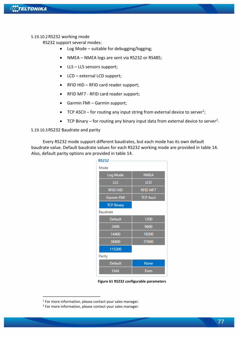
77
5.19.10.2 RS232 working mode RS232 support several modes:
• Log Mode – suitable for debugging/logging;
• NMEA – NMEA logs are sent via RS232 or RS485;
• LLS – LLS sensors support;
• LCD – external LCD support;
• RFID HID – RFID card reader support;
• RFID MF7 - RFID card reader support;
• Garmin FMI – Garmin support;
• TCP ASCII – for routing any input string from external device to server1;
• TCP Binary – for routing any binary input data from external device to server2.
5.19.10.3 RS232 Baudrate and parity Every RS232 mode support different baudrates, but each mode has its own default
baudrate value. Default baudrate values for each RS232 working mode are provided in table 14. Also, default parity options are provided in table 14.
Figure 61 RS232 configurable parameters
1 For more information, please contact your sales manager. 2 For more information, please contact your sales manager.

78
Table 14. Default Baudrate and Parity by RS232/RS485 working Mode
Mode RS232 default Baudrate RS485 default Baudrate Default Parity (RS232 only)
Log Mode 115200 115200 None
NMEA 115200 115200 None
LLS 19200 19200 None
LCD 57600 - None
RFID HID 57600 - None
RFID MF7 9600 - None
Garmin FMI 9600 - None
TCP ASCII 115200 57600 None
TCP Binary 115200 57600 None
5.19.10.4 RS232 TCP Binary mode settings RS232 TCP Binary Mode has additional configurable parameters for advanced data filtering.
Figure 62 RS232 TCP Binary mode settings
5.19.10.5 RS232 Garmin Mode settings
Garmin FMI mode has additional filtering capabilities. It is possible to filter Ping and
Unicode packets. If Ping filter will be enabled, then Ping packets will be blocked. If Unicode filter
will be enabled, then Unicode packets will not be sent to server. Both filters may be enabled for
simultaneous work.
Figure 63 RS232 Garmin Mode settings
5.19.10.6 RS485 working mode RS485 support several modes:
• Log Mode – suitable for debugging/logging;
• NMEA – NMEA logs are sent via RS232 or RS485;
• LLS – LLS sensors support;
• TCP ASCII – for routing any input string from external device to server;

79
• TCP Binary – for routing any binary input data from external device to server.
5.19.10.7 RS485 Baudrate Every RS485 mode support different baudrates, but each mode has its own default
baudrate value. Default baudrate values for each RS485 working mode are provided in table 14.
Figure 64 RS485 configurable parameters
5.19.10.8 RS485 LLS Sensors LLS addresses may be configured for 5 LLS sensors. If at least one LLS sensor is connected
to FMB125 when configuring device with configurator LLS sensor ID will be entered automatically.
Figure 65 RS485 five LLS Sensors address selection window.
6 RS232 and RS4851
6.1 RS485 Interface
RS485 supports only Half Duplex communication. It means that at the same time you can’t send/receive Data.
1 Only support FMB125 device

80
When activated RS485 driver chip draws constant 30mA current. When Entering Sleep or Deep sleep, Chip will be powered off too. FMB125 RS485 Pins connection diagram are shown on the Figure 66:
Figure 66 connection block diagram
6.2 RS485 modes
In Configurator windows select RS232/RS485 window where is RS485 Settings (more information about available RS232/RS485 parameters configuration in 5.19.10 FMB125 RS232\RS485 parameters configuration chapter).
6.2.1 RS485 transmit (FMB log) mode
RS-485 works in transmit mode, it prints FM log. It won’t respond to commands.
Figure 67 RS485 FMB Log Mode configuration
6.2.2 RS485 transmit (GNSS NMEA) mode
RS-485 works in transmit mode, it prints GNSS NMEA log. It won’t respond to commands.
Figure 68 RS485 GNSS NMEA Mode configuration

81
6.2.3 RS485 receive (LLS) mode
The mode supports up to five LLS fuel level sensors. Baud rate must be 19200. LLS have receiver id. LLS mode configuration shown in Figure 69.
6.2.4 RS485 TCP (ASCII, Binary) mode
In TCP ASCII mode link with external device using text messages can be established.
Figure 70 RS485 TCP Ascii Mode configuration
TCP Binary mode is the same as above but binary
messages will be accepted.
Figure 71 RS485 TCP Binary Mode configuration
6.3 RS232 Interface
RS-232 supports Full Duplex communication. It means that at the same time you can send/receive Data, because it uses separate lines for transmitting and receiving data.
Most of the modes are the same as RS-485. FMB125 RS232 pins connection diagram are shown on the Figure 66.
6.4 RS232 modes
In Configurator windows select RS232/RS485 window where is RS232 Settings (more information about available RS232/RS485 parameters configuration in 5.19.10 FMB125 RS232\RS485 parameters configuration chapter).
Most of the modes are the same as RS-485. Same modes are: log mode, NMEA, LLS, TCP Ascii and TCP Binary.
In RS232 LLS mode only one LLS fuel level sensor can be connected.
6.4.1 RS232 LCD mode
In this mode you can communicate with server through terminal. Link between FM and server has to be established for this functionality to work.
Figure 69 RS485 LLS Mode configuration

82
Figure 72 RS232 LCD Mode configuration
6.4.2 RS232 RFID HID/RFID MF7 mode
The difference between RFID Mode and RFID MF7 Mode is that in RFID Mode FMB125 understands RFID messages that are in hexadecimal format and RFID MF7 Mode understands messages that are in decimal format. For example:
RFID Mode message – “$aa$02$03$04$17$89$00$01” RFID MF7 Mode message – “1213141519” The chosen mode has to correspond to the RFID reader’s mode. What type of RFID is sent
to FMB125 depends on the reader. For more information about RFID ID’s and devices, please contact to your local sales
representative.
Figure 73 RS232 RFID HID Mode configuration

83
Figure 74 RS232 RFID MF7 Mode configuration
6.4.3 RS232 GARMIN mode
Garmin provides a Fleet Management Interface Tool Kit which connected to FMB125 enables the driver to have a "screen" in their vehicle for real-time navigation, messaging, and job dispatch capabilities to help them be more efficient.
Figure 75 RS232 Garmin FMI Mode configuration
Figure 76 RS232 Garmin Mode Settings configuration
FMB125 and Garmin operational scheme is shown in Figure 77 below:
Figure 77 FMB125+Garmin operational scheme

84
6.5 Garmin protocols
The following is a list of protocols supported and the corresponding feature/benefit. FMB125 can fully support Fleet Management Interface (FMI) versions up to 2.1. Other or higher versions may be supported, but Teltonika is not responsible for the changes made by Garmin, which may affect the work of FMB125 and Garmin products. For more information about Garmin products and FMI versions, please go to http://www8.garmin.com/solutions/pnd/supportedproducts.jsp. Notice that some Garmin products use different connection cables than others.
6.5.1 Standard protocols
Text Message Protocol: • Allows text messages sent to device to be displayed in "inbox" on unit. • Garmin can provide confirmation that message was read. • Garmin can also provide a yes/no box below the text of the message to enable a simple
quick response. • Messages can be up to 199 characters in length. • Messages can also be generated from device and sent to dispatch/office. • Messages received will be notified to driver through a pop-up alert on Garmin screen. • Garmin provides a "virtual keyboard" on device through a touch-screen format for all text
communication. Stop (Destination) Protocol: • Garmin can display a list of Stops/Jobs reported to the device in a separate icon called
"My Stops". • Driver has ability to navigate directly to Stop from list. • Garmin can provide status on current Stop in progress. • Is driver stopped at location? • How far has Driver progressed through the list of Stops? • Garmin can also provide confirmation that driver has received a particular Stop, read the
details, or deleted it from list. • Can provide confirmation that a Stop has been completed. Estimated Time of Arrival Protocol: • Dispatcher/office can request the ETA of the current stop/job in progress. • Garmin will notify the actual time of arrival as well as distance remaining to stop. Auto-Arrival at Stop Protocol: • This feature is used to tell the Garmin PND to automatically detect that it has arrived at a
Stop and then to prompt the driver if they would like to mark the Stop as done and begin navigating to next Stop on the list. • Auto-arrival can be determined by how long the unit is stopped close to the destination
(in the event driver has to park and walk) or by how close the unit needs to be to the destination before the Auto-arrival feature is activated.
Data Deletion Protocol: • Dispatch/office has the ability to wipe clean the data on the Garmin PND.
• Clean up messages in inbox/remove stops.

85
6.5.2 Enchanced protocols
Canned Responses/Messages: • Fleet managers can communicate by sending up to 200 "canned" responses from server
to be stored directly on Garmin devices. • Up to 50 of these canned responses can be utilized for any given scenarios. • Drivers can store up to 120 canned messages, eliminating the need to type while driving. Status Protocol:
• Up-to-the-minute communications that allow drivers to automatically send status
updates. • Driver's units can store up to sixteen status indicators such as start/stop shift, on/off break, etc.
6.5.3 Supported features on TAVL client application
TAVL client application lets user to use the following features of GARMIN FMI: 1. Text messaging; 2. Destination message; 3. ETA request.
6.5.4 Text messaging
Text messaging feature lets user to communicate with driver (user that uses Garmin device) by sending text messages via GPRS.
6.5.5 Destination message
Destination message is used to inform a driver of a new destination. When Garmin device receives a destination message from server it displays it as “Stop” to the driver and also gives the driver ability to start navigating to the “Stop” location. New destination in Tavl client is represented as Geozone so new Geozone (as destination) has to be created first.
6.5.6 ETA request message
ETA (Estimated Time of Arrival) request message is used when user wants to know expected arrival time to currently active destination and distance (in meters) from current object location to currently active destination.
7 FMB1YX with LV-CAN200 and ALL-CAN300 Can Adapters
7.1 Purpose of Can Adapters LV-CAN200 and ALL-CAN30
LV-CAN200 is used to listening data from light vehicles, while ALL-CAN300 is used to listening
data from any type of transport: light vehicles, Trucks, busses, agriculture and other special transport.
With those adapters FMB1YX device is able to collect and send vehicle data.

86
Figure 78 connection block diagram
Table 23. LV-CAN200 and ALL-CAN300 Technical characteristics
PARAMETER VALUE
Supply voltage 9 to 50V
Power supply current Average 10mA Max (peak) 100mA
Working temperature -40..85 ºC
Max working humidity 60 % (non condensate)
7.2 LV-CAN200 and ALL-CAN300 program number selection
LV-CAN200 or ALL-CAN300 must be set to program number which depends on vehicle model. Needed program number is always written on LV-CAN200 or ALL-CAN300 mounting scheme. Please contact Your Teltonika sales manager to get latest supported vehicle list and mounting scheme for your vehicle, please provide CAR manufacturer, model and year information.
7.2.1 LV-CAN200 and ALL-CAN300 program number configuration via SMS command
LV-CAN200 and ALL-CAN300 program number can be set remotely, using SMS command (more lvcan commands in chapter SMS command list):
lvcansetprog X
X is new program number value.
7.2.2 LV-CAN200 and ALL-CAN300 program number configuration via configurator
LV-CAN200 and ALL-CAN300 program number can be set via configurator: LVCAN -> Program Number. When program number is entered press ‘Save to device’ button that entered program number saves into FMB1YX.
7.2.3 Selecting LV-CAN200 and ALL-CAN300 program number manually
Steps to set program number:
• Hold SWITCH down till LED stars blinking
• Release the SWITCH
PC
FMB1YX
USB
USB Cable
ALL-CAN300 / LV-CAN200
FMB1YX
USB
Connection cable

87
• Then LED starts blinking and counting first digit of program number, (one blink
means digit 1, two blink digit 2 etc.)
• To stop counter push SWITCH
• Release the SWITCH, then LED starts blinking and counting second digit of program
number
• To stop counter push SWITCH
• Release the SWITCH, then LED starts blinking and counting third digit on program
number
• To stop counter push SWITCH
• Release SWITCH, if programming is succeded LED will blink 10 times
Figure 79 Adapter signaling led

88
7.3 SIMPLE-CAN - contactless CAN-BUS reader
SIMPLE-CAN is contactless adapter used to read
vehicle CAN data with LV-CAN200, ALL-CAN300. If LV-
CAN200 or ALL-CAN300 connection requires two CAN lines
to get all data, then you need two SIMPLE-CAN readers
TECHNICAL DETAILS
• Power supply voltage 9-63 V
• Power supply current:
Mode 12V 24V
Active 8.3 mA 4.3 mA
Standby 1.6 mA 0.91 mA
• CAN-BUS speeds from 33,33 to 500 kb/s
• Automatically sets CAN Low, CAN High polarity
• Automatically adjusts signal level and speed
SIMPLE-CAN works in the listening mode only, so not all the data available on the CAN-BUS
may be received using this solution. The device automatically sets CAN L/H polarity, but the
calibration has to be always executed during installation process. Connection of previously
calibrated unit to another car needs new calibration because the reader automatically adjusts
signal level and speed to different CAN-BUSes. The device also automatically adapts to the
found noise level.
Figure 81 Teltonika SIMPLE-CAN pinout
After power supply connecting, LED shines continuously. It means that device waits
for calibration. Calibration process has to be carried out when CAN-BUS twisted pair is tightened
on SIMPLE-CAN and when the ignition is ON. Please press the switch shortly and wait for the LED
Figure 80 Teltonika SIMPLE-CAN

89
to start blinking every 1 second. Automatic calibration process takes up to 10 seconds depending
on the vehicle's model. Correct calibration process is confirmed by LED's every 2 seconds blink
(when the CAN-BUS is active). When the CAN-BUS enters sleep mode, SIMPLE-CAN device does it
also and takes 1,6mA/12V. In the sleep mode LED does not shine. If after calibration process LED
shines continuously, it means that device is not calibrated yet, CAN-BUS transmission has failed
or ignition during calibration was not ON.
7.4 Connecting FMB1YX Can adapters ALL-CAN300 and LV-CAN200
Connect LV-CAN200/ ALL-CAN300 Pin 5 to FMB1YX Pin 12 (INPUT 5) LV-CAN200/ ALL-
CAN300 Pin 6 to FMB1YX Pin 6 (INPUT 6), connect Light Vehicles Can adapter to other end of the
cable.
Connect Light Vehicles Can adapter Pin 1 and Pin 2 to cars CAN bus. CAN interface location
of the supported light vehicle is described on mounting scheme.
Connect car power supply lines to Pin 3 positive, Pin 4 Negative.
Pins 9, 10 connections are optional it depends on exact car model.
For exact pinout see sticker on Light Vehicles Can adapter.
Figure 82 LV-CAN200 Adapter connection cable pinout
Figure 83 ALL-CAN300 Adapter connection cable pinout
Attention! For detailed connection diagram of adapter to light vehicle
please contact Teltonika, LTD sales representative and provide CAR
manufacturer, model and year information.
Attention! Do not swap CAN L and CAN H lines.
Do not swap power supply lines. Make sure that voltage do not exceeds
30V. Power supply lines should be connected at the end of installation work.

90
7.5 FMB1YX ALL-CAN300 and LV-CAN200 parameters configuration
Because FMB1YX have LV-CAN200 / ALL-CAN300 RX and TX in its own pinout device configuration can be performed via micro-USB when CAN adapter are connected in vehicle.
When FMB1YX are connected to configurator and at the same moment to LV-CAN200 or ALL-CAN300, in configurator LVCAN section user can see all information that is received from vehicle, that data are marked with green backbround color. Information in this section is automaticali refreshed. CAN bus data which can be read from your car is shown in “Light or ALL Vehicles Can adapter supported cars” document.
The LVCAN I/O element can be configured like any other I/O element in FMB1YX configurator.
When using offline configuration metod user can select which CAN data will be red from LV-CAN200 or ALL-CAN300 and directly sent to server without connection to adapter. Please note that parameters depend on vehicle manufacturer and vehicle model. Please for further information check “Light and All Vehicles Can adapter supported cars” document.
All information about I/O element parameters description is in chapter 5.17 I/O settings. All LV-CAN200/ALL-CAN300 I/O parameters configuration settings are described in
“FMB1YX Protocols” document, except ALL-CAN300 bitmasks, they are described in table 24 below.
Figure 84 Confgurator example
Table 24. ALLCAN300 IO element values bitmasks
Property Name Size, Bytes
Value bitmasks
Control state flags 4 Byte0 (LSB): 0x01 – STOP 0x02 – Oil pressure / level 0x04 – Coolant liquid temperature / level 0x08 – Handbrake system 0x10 – Battery charging 0x20 – AIRBAG
Byte1: 0x01 – CHECK ENGINE

91
Property Name Size, Bytes
Value bitmasks
0x02 – Lights failure 0x04 – Low tire pressure 0x08 – Wear of brake pads 0x10 – Warning 0x20 – ABS 0x40 – Low Fuel
Byte2: 0x01 – ESP 0x02 – Glow plug indicator 0x04 – FAP 0x08 – Electronics pressure control 0x10 – Parking lights 0x20 – Dipped headlights 0x40 – Full beam headlights
Byte3: 0x40 – Passenger's seat belt 0x80 – Driver's seat belt
Agricultural machinery flags
8 Byte0 (LSB): 0x01 – Mowing 0x02 – Grain release from hopper 0x04 – First front hydraulic turned on 0x08 – Rear Power Take-Off turned on
Byte1:
0x01 – Excessive play under the threshing drum 0x02 – Grain tank is open 0x04 – 100% of Grain tank 0x08 – 70% of Grain tank 0x10 – Drain filter in hydraulic system of drive cylinders is plugged 0x20 – Pressure filter of drive cylinders hydraulic system is plugged 0x40 – Alarm oil level in oil tank 0x80 – Pressure filter of brakes hydraulic system is plugged
Byte2:
0x01 – Oil filter of engine is plugged 0x02 – Fuel filter is plugged 0x04 – Air filter is plugged 0x08 – Alarm oil temperature in hydraulic system of chasis 0x10 – Alarm oil temperature in hydraulic system of drive cylinders 0x20 – Alarm oil pressure in engine 0x40 – Alarm coolant level 0x80 – Overflow chamber of hydraulic unit
Byte3:

92
Property Name Size, Bytes
Value bitmasks
0x01 – Unloader drive is ON. Unloading tube pivot is in idle position 0x02 – No operator! 0x04 – Straw walker is plugged 0x08 – Water in fuel 0x10 – Cleaning fan RPM 0x20 – Trashing drum RPM
Byte4: 0x02 – Low water level in the tank 0x04 – First rear hydraulic turned on 0x08 – Standalone engine working 0x10 – Right joystick moved right 0x20 – Right joystick moved left 0x40 – Right joystick moved front 0x80 – Right joystick moved back
Byte5: 0x01 – Brushes turned on 0x02 – Water supply turned on 0x04 – Vacuum cleaner 0x08 – Unloading from the hopper 0x10 – High Pressure washer (Karcher) 0x20 – Salt (sand) disperser ON 0x40 – Low salt (sand) level
Byte6: 0x01 – Second front hydraulic turned on 0x02 – Third front hydraulic turned on 0x04 – Fourth front hydraulic turned on 0x08 – Second rear hydraulic turned on 0x10 – Third rear hydraulic turned on 0x20 – Fourth rear hydraulic turned on 0x40 – Front three-point Hitch turned on 0x80 – Rear three-point Hitch turned on
Byte7: 0x01 – Left joystick moved right 0x02 – Left joystick moved left 0x04 – Left joystick moved front 0x08 – Left joystick moved back 0x10 – Front Power Take-Off turned on
Security state flags 8 Byte0 (LSB): 0x20 – bit appears when any operate button in car was put 0x40 – bit appears when immobilizer is in service mode 0x80 – immobiliser, bit appears during introduction of a programmed sequence of keys in the car.
Byte1: 0x01 – the key is in ignition lock 0x02 – ignition on 0x04 – dynamic ignition on

93
Property Name Size, Bytes
Value bitmasks
0x08 – webasto 0x20 – car closed by factory's remote control 0x40 – factory-installed alarm system is actuated (is in panic mode) 0x80 – factory-installed alarm system is emulated by module
Byte2: 0x01 – parking activated (automatic gearbox) 0x10 – handbrake is actuated (information available only with ignition on) 0x20 – footbrake is actuated (information available only with ignition on) 0x40 – engine is working (information available only when the ignition on) 0x80 – revers is on
Byte3: 0x01 – Front left door opened 0x02 – Front right door opened 0x04 – Rear left door opened 0x08 – Rear right door opened 0x10 – engine cover opened 0x20 – trunk door opened
Byte4: 0x01 – car was closed by the factory's remote control 0x02 – car was opened by the factory's remote control 0x03 – trunk cover was opened by the factory's remote control 0x04 – module has sent a rearming signal 0x05 – car was closed three times by the factory's remote control - High nibble (mask 0xF0 bit) 0x80 – CAN module goes to sleep mode
Tachograph driver card presence
1 0x00 – No driver card 0x01 – Driver1 card presence 0x02 – Driver2 card presence 0x03 – Driver1 and driver2 cards present
Driver 1 states 1 0xX0 – break/rest 0xX1 – availability 0xX2 – work 0xX3 – driving 0x0X – no time-related warning detected 0x1X – limit #1: 15 min before 4 1/2 h 0x2X – limit #2: 4 1/2 h reached (continuous driving time exceeded) 0x3X – limit #3: 15 minutes before optional warning 1 0x4X – limit #4: optional warning 1 reached
Driver 2 states 1

94
Property Name Size, Bytes
Value bitmasks
0x5X – limit #5: 15 min before optional warning 0x6X – limit #6: optional warning 2 reached
7.6 Send data with 0, if ignition is off
Depending on LV-CAN200 / ALL-CAN300 I/O parameters and ignition status, FMB1YX can send locked (last known) LV-CAN200 / ALL-CAN300 I/O parameters values, reset values (set to 0) and active (real time) parameters values. When ignition is off, LV-CAN200 / ALL-CAN300 I/O parameters values sent to server are:
LV-CAN200 / ALL-CAN300 I/O element
Status
Vehicle Speed reset
Accelerator pedal position reset
Total fuel used lock
Fuel level (liters) lock
Engine RPM reset
Total mileage lock
Fuel level (proc.) lock
Program number lock
Module ID lock
Engine Work Time lock
Engine Work Time (counted) lock
Total Mileage (counted) lock
Fuel Consumed (counted) lock
Fuel Rate reset
AdBlue Level (percent) lock
AdBlue Level (liters) lock
Engine Load reset
Engine Temperature active
Axle 1 Load lock
Axle 2 Load lock
Axle 3 Load lock
Axle 4 Load lock
Axle 5 Load lock
Control State Flags active
Agricultural Machinery Flags active
Harvesting Time lock
Area of Harvest reset
Mowing Efficiency active
Grain Mown Volume active
Grain Moisture active
Harvesting Drum RPM reset
Gap Under Harvesting Drum active
Security State Flags active

95
LV-CAN200 / ALL-CAN300 I/O element
Status
Tachograph Total Vehicle Distance lock
Trip Distance reset
Tachograph Vehicle Speed reset
Tachograph Driver Card Presence active
Driver1 States active
Driver2 States active
Driver1 Continuous Driving Time active
Driver2 Continuous Driving Time active
Driver1 Cumulative Break Time active
Driver2 Cumulative Break Time active
Driver1 Selected Activity Duration active
Driver2 Selected Activity Duration active
Driver1 Cumulative Driving Time active
Driver2 Cumulative Driving Time active
8 SMS/GPRS COMMAND LIST1
All commands are case sensitive. While FMB1YX operates in Deep Sleep mode and user tries to send SMS/GPRS message it cannot arrive to FMB1YX device, because GSM/GPRS module is disabled most of the time (wake up depends on Send Period parameter). FMB1YX will receive the SMS/GPRS when it wakes up (exits deep sleep mode).
While FMB1YX is in GPS Sleep or Online Deep Sleep mode and user tries to send SMS/GPRS message it will arrive to device, because GSM module is enabled.
8.1 SMS/GPRS command list
Table 15. Common SMS/GPRS commands
Command Description Response
getinfo Device runtime system information Yes
getver Returns code version, device IMEI, modem app version, RTC time, Init time, Uptime and BT MAC address.
Yes
getstatus Modem Status information Yes
getgps Current GPS data, date and time. Yes
getio Readout analog input,digital input and output Yes
ggps Returns location information with Google maps link Yes
readio # Returns IO status, # AVL ID Yes
cpureset Resets device No
1 GPRS commands require Codec 12 protocol

96
Command Description Response
getparam # Returns selected parameter value, # param ID Yes
setparam #:# Sets selected parameter value. 1.# - first ID value. 2.# - New first Parameter Value 3.# - second ID value. 4.# - New second Parameter Value 5.# - third ID value. 6.# - New third Parameter Value SMS command of limited to 160 characters.
Yes
setparam #:#;#:#;…
flush #,#,#,#,#,#,# Redirects device to other server. 1.# - IMEI 2.# - APN 3.# - LOGIN 4.# - PASS 5.# - IP 6.# - PORT 7.# - MODE (0-TCP/1-UDP)
Yes
countrecs Returns records number Yes
deleterecords Delete all records from SD card Yes
FMB120 and FMB122: setdigout ## Y1 Y2 FMB125: setdigout # Y
Set digital output 1.# – 0 or 1 (0 - OFF or 1 – ON) for DOUT1 2.# – 0 or 1 (0 - OFF or 1 – ON) for DOUT2 Y1 – timeout value for DOUT1 if needed (in seconds) Y2 – timeout value for DOUT2 if needed (in seconds)
Yes
battery Returns battery state info. Yes
wdlog Returns all information about “watch dogs” restarts. Yes
defaultcfg Load default configuration. Yes
setkey # # Add new or change current configuration keyword. If device is locked, keyword cannot be changed 1.# - old keyword (if adding new keyword space (view chapter 5.1.2)) 2.# - new keyword
Yes
delkey # Remove existing keyword. (If device is locked, keyword cannot be changed) # - old keyword
Yes
bbread # Return black box information (HEX value of event ID and HEX value of custom data field (optional)). 1.# - returns entered number of latest events. When # is omitted the latest events are packed to single SMS.
Yes
bbinfo # Return same information as bbread command but additional all events timestamp is written in HEX. 1.# - returns entered number of latest events. When # is omitted the latest events are packed to single SMS.
Yes

97
Command Description Response
sdformat Format SD card. Yes
Table 16. SMS commands related to features
Command Description Response
fc_reset Resets fuel consumption parameters Yes
towingreact Towing reactivation Yes
auto_calibrate Calibrate position if car accelerate straight to > 30 km/h for 5 sec.
Yes
position_info Indicates what axis is set to the front of the car. Yes
calibrate Zero out accelerometer axis (vehicle speed must be 0 km/h.)
Yes
odoset:# Set total odometer value. # - new odometer value in km
Yes
odoget Display current odometer value Yes
Table 17. SMS commands related to Bluetooth
Command Description Response
btgetlist # Returns requested Bluetooth list. # - 0,1 or 2 (0 – Discovered, 1 – Paired, 2 – Connected)
Yes
btscan Starts Bluetooth scan. Yes
btvisible # Sets Bluetooth to visible with TMO. # - visibility TMO (from 1 to 255 seconds).
Yes
btrelease # Disconnects from current device and pauses auto connect functionality for TMO # - none or TMO (from 1 to 255 seconds).
Yes
btunpair # Unpair Bluetooth device. # - all, BT address (all – unpair all devices, BT address – unpair only specified MAC address).
Yes
Table 18. SMS commands related to OBD
Command Description Response
obdinfo If connected with Bluetooth OBD dongle displays all available information from OBD.
Yes
faultcodes If connected with Bluetooth OBD dongle display all visible fault codes.
Yes
cleardtc Clears all vehicle stored foult codes. No
getvin Get vechicle VIN code, if OBD dongle is connected. Yes
Table 19. SMS commands related to LV-CAN200/ALL-CAN300
Command Description Response
lvcansetprog # Set program number to LV-CAN200/ ALL-CAN300 that is connected to FMB1YX. # thre digits number that identity vehicle.
Yes
lvcansimpletacho # Add or remove simpletacho start byte. No

98
Command Description Response
# - 0 or 1 (0 – don’t add start byte, 1 – add start byte).
lvcangetprog Get program number from LV-CAN200/ ALL-CAN300 that is connected to FMB1YX.
Yes
lvcangetinfo Get information about connected LV-CAN200/ ALL-CAN300
Yes
lvcanclear # Clear Total Mileage (counted), Engine Work Time (counted), Fuel Consumed (counted) parameters values. # - parameter (0 – Engine work time (counted), 1 – Fuel Consumed (counted), 2 – Vehicle Mileage (counted)).
Yes
allcanmode Turn on ALL-CAN300 mode Yes
lvcanmode Turn on LV-CAN200 mode Yes
lvcanfaultcodes Read DTC fault codes Yes
Parameter ID consists of 3 or 5 digits. Detailed list of parameters and IDs can be found in
chapter 7 PARAMETER LIST. Example: ‘username password setparam 2001:wap’ will change configured APN. Example: ‘username password setparam 2001:wap;2002:user;2003:pass’ will change
configured APN name, APN username and APN password. SMS command of limited to 160 characters.
Example: ‘username password setdigout 10 60’ will set digital output ON for 60s.
8.1.1 getinfo
Response details Description
RTC RTC Time
Init Device initialization time
UpTime Total up time (in seconds)
PWR Last restart reason
RST Total restarts count
GPS GPS receiver state. 0 – OFF, 1 – ON without fix, 2 – ON with fix, 3 – In sleep mode.
SAT Average satellites
TTFF Time To First Fix
TTLF Time To Last Fix
NOGPS How much time no GPS fix (h:min)
SR Number of Sent Records
FG Failed GPRS counter
FL Failed link counter
SMS Sent SMS Counter
REC Records Found – number of records in the memory.
MD Data Mode state. 0 – Home and Stop, 1 – Home and Moving, 2 – Roaming and Stop, 3 – Roaming and Moving, 4 – Unknown and Stop, 5 – Unknown and Moving

99
Example: “RTC:2017/6/16 7:13 Init:2017/6/16 5:44 UpTime:4744s PWR:PwrVoltage RST:0 GPS:1 SAT:0 TTFF:0 TTLF:0 NOGPS: 1:18 SR:0 FG:200 FL:0 SMS:3 REC:42 MD:1”.
8.1.2 getver
Response details Description
Ver Firmware version
GPS Version of GPS module
Hw Version of hardware
Mod HW version modification
IMEI Device IMEI
Init Device initialization time
Uptime Total up time (in seconds)
BT Device MAC address Example: “Ver:02.00.01_06 GPS:AXN_3.80_3333_16070400,0000,, Hw:FMB1YX Mod:4
IMEI:352094082042885 Init: 2017-6-16 5:54 Uptime: 16574 BT:31F5BFE66261”.
8.1.3 getstatus
Response details Description
Data Link Indicate module connection to server at the moment: 0 – Not connected, 1 – connected
GPRS Indicate if GPRS is available at the moment
Phone Voice Call status: 0 – ready, 1 – unavailable, 2 – unknown, 3 –ringing, 4 – call in progress, 5 – asleep
SIM SIM Status: 0-ready, 1-pin, 2-puk, 3-pin2, 4-puk2
OP Connected to GSM Operator: numerical id of operator
Signal GSM Signal Quality [0-5]
NewSMS Indicate if new message received
Roaming 0 – Home Network, 1 – roaming
SMSFull SMS storage is full? 0 – ok, 1 – SMS storage full
LAC GSM Tower Location Area Code
Cell ID GSM Tower Cell ID Code
Example: “Data Link: 0 GPRS: 1 Phone: 0 SIM: 0 OP: 24602 Signal: 5 NewSMS: 0 Roaming: 0 SMSFull: 0 LAC: 1 Cell ID: 3055”.
8.1.4 getgps
Response details Description
GPS Indicates valid (1) or invalid (0) Gps data
Sat Count of currently available satellites
Lat Latitude (Last good Latitude)
Long Longitude (Last good Longitude)
Alt Altitude
Speed Ground speed, km/h
Dir Ground direction, degrees
Date Current date
Time Current GMT time

100
Example: “GPS:1 Sat:0 Lat:54.666042 Long:25.225031 Alt:0 Speed:0 Dir:0 Date: 2017/6/16 Time: 12:52:30”.
8.1.5 getio
Response details Description
DI1 Digital input 1 value
DI21 Digital input 2 value
DI32 Digital input 3 value
AIN1 Analog input 1 value
AIN23 Analog input 2 value
DO1 Digital output 1 value
DO24 Digital output 2 value
Example: “DI1:0 DI2:0 DI3:0 AIN1:0 AIN2:0 DO1:0 DO2:0”.
8.1.6 ggps
Response details Description
D Date
T Time
S Actual Speed
C Latitude (Last good Latitude), Longitude (Last good Longitude)
Url Google Maps Link Example (if no GNSS FIX): “GPS Data not Available. No GPS signal”. Example: D:17/1/9 T:12:52:30 S:0.00 C:54.666042, 25.225032 Url:
http://maps.google.com/?q=54.666042,25.225032&om=1speed:0
8.1.7 readio #
Response details Description
ID I/O element ID
Value I/O Element value Example (if wrong ID): “Not supported or not enabled IO element requested”. Example: “Param ID:239 Value:0”.
8.1.8 getparam
Read parameter value. ID consists of 3 or 5 digits. A detailed list of parameters and identifiers can be found in this chapter next later.
Example: ‚getparam 2001‘ command will request APN name Answer: Param ID:2001 Value:wap
8.1.9 setparam
Read parameter value. ID consists of 3 or 5 digits. A detailed list of parameters and identifiers can be found in this chapter next later.
1 FMB125 don’t have Digital input 2 2 FMB125 don’t have Digital input 3 3 FMB125 don’t have Analog input 2 4 FMB125 don’t have Digital output 2

101
Example: ‚setparam 2001:wap‘ will change configured APN name Answer: Param ID:2001 Value:wap2
Example: ‘setparam 2001:wap;2002:user;2003:pass’ will change configured APN name, APN username and APN password. SMS command of limited to 160 characters.
8.1.10 flush #,#,#,#,#,#,#
Initiates all data sending by GPRS to specified target server. Comma separated parameters go as numbered: 1.# - IMEI 2.# - APN 3.# - GPRS LOGIN 4.# - GPRS PASSWORD 5.# - IP 6.# - PORT 7.# - MODE (0-TCP/1-UDP) Parameters are separated by comma (no spaces needed). In case you don’t need to enter parameter (APN Login/ APN Pass) – do not put space, simply put comma and write next
parameter. Parameters are separated by comma (no spaces needed). In case you don’t need to enter parameter (APN Login/ APN Pass) – do not put space, simply put comma and write next
parameter. Example: opa opa flush 353976012555151,banga,,,212.47.99.62,12050,0
Response details Description
FLUSH SMS Accepted FLUSH SMS Accepted
# records found on FLASH Number of records found on FLASH
Minimum Records to Send: # Number of minimum saved records to send
GPRS Enabled: # State of the GPRS connection, 0 – disabled; 1 – enabled
Time Sync: # Indicates time synchronization on the device, 0 – not synchronized; 1 – synchronized
Example: “FLUSH SMS Accepted. 11 records found on FLASH. Minimum Records to Send: 1. GPRS Enabled: 1. Time Sync: 1.”.
8.1.11 countrecs
Returns currently records number in SD card or device memory. Example (if more that 100): “more then 100 records found”. Example: “25 records found”.
8.1.12 deleterecords
Delete all records from SD card or device memory.
102
8.1.13 setdigout
Sets digital outputs to ON or OFF state (timeout is valid only when DOUT state is changing from OFF to ON)
Example: ‘setdigout 01 30 60’ will set DOUT1 to low level (for infinite time) and DOUT2 to high level for 60 seconds,
‘setdigout 11’ will set DOUT1 and DOUT2 to high level for infinite time.
FMB125 have only one digital output, so only one DOUT must be described in command. Example: ‘setdigout 1 60’ will set DOUT1 to high level for 60 seconds.
8.1.14 battery
Response details Description
BatState Battery connected (1) or disconnected (0) from device
FSMState Current battery state
ChargerIC Battery charging status
ExtV External Voltage
BatV Battery voltage
BatI Battery charging current Example: “BatState: 1 FSMState: ACTIVE ChargerIC: OFF ExtV: 11796 BatV: 3942 BatI: 0”.
8.1.15 fc_reset
Reset GPS fuel consumption value. Example: “Fuel Consumption parameters reseted”.
8.1.16 towingreact
Reactivates Towing Detection to initial state (does not wait for ignition to be OFF). Useful when generated false Towing event and needs reactivation.
8.1.17 odoset:#
Set new total odometer value in km. Example: “Saved Odometer Value: 5000 km”.
8.1.18 odoget
Get total odometer value in km. Example: “Current Odometer Value:5000 km”.
8.1.19 btgetlist #
btgetlist command needs argument what list should be printed! btgetlist 0; device will respond with BT_LIST_Discovered btgetlist 1; device will respond with all paired devices btgetlist 2; device will respond with connected blutetooth device
Note: Without argument it is always 0 i.e BT_LIST_Discovered In FW 01.00.23 btgetlist (without args) will not respond (as unknown command).

103
8.1.20 obdinfo
Response details Description
LIST of OBD info Protocol, VIN, AdaptiveTiming value, requested PID counter, OBD application state, available vehicle PIDs, mil status, number of DTCs
Example:
“Prot:0,VIN:N/A,TM:10,CNT:0,ST:OFF,P1:0x0,P2:0x0,P3:0x0,P4:0x0,MIL:0,DTC:0,ID0,Hdr:0,Phy:0”.
8.1.21 faultcodes
Response details Description
LIST Returns list of fault codes; response when no faults: “No fault codes detected.”
Example: “P0100,P0200,P0300,C0300,B0200,U0100”.
8.1.22 setkey # #
"setkey <oldkeyword> <newkeyword>" - Set new or change the keyword. Configuration should be not locked.
Example: New keyword (set): <name>{space}<pass>{space}setkey{space}{space}<newkeyword>
Change keyword (change): <name>{space}<pass>{space}setkey{space}<oldkeyword>{space}<newkeyword>
8.1.23 delkey # #
"delkey <keyword>" - Deletes current keyword. Configuration keyword should be configured and not locked.
Example: <name>{space}<pass>{space}delkey{space}<keyword>
8.1.24 bbread #
# describes start offset and is an optional field. # of value 20 means that blackbox data is requested starting from 20th latest event. When # is omitted the latest events are packet to single SMS.
Example: X1:Y1,X2:Y2,…,Xn:Yn, where Xn – HEX value of event ID. Yn – HEX value of custom data field (optional).
8.1.25 bbinfo #
# describes start offset and is an optional field. # of value 20 means that blackbox data is requested starting from 20th latest event. When # is omitted the latest events are packet to single SMS.
Example: X1-Y1:Z1,X2-Y2:Z2,…,Xn-Yn:Zn, where Xn – timestamp in HEX. Yn – HEX value of event ID. Zn – HEX value of custom data field (optional).

104
8.1.26 sdformat
Format sd card (deleta all information from SD card).
8.1.27 lvcansetprog #
Set program number to LV-CAN200 or ALL-CAN300 which is connected to FMB1YX.
8.1.28 lvcangetprog
Get currently using program number from LV-CAN200 or ALL-CAN300.
8.1.29 lvcangetinfo
Response details Description
LIST of LV-CAN200 or ALL-CAN300 info
Program number, SW creation date, SW revision, Kern version, Option and its ID, Simple tacho configuration.
8.1.30 lvcanclear #
It is possible to clear Total Mileage (counted), Engine Work Time (counted), Fuel Consumed (counted) parameters with following SMS command. SMS text:”lvcanclear #”
Possible values of #:
0 – Engine work time (counted); 1 – Fuel Consumed (counted); 2 – Vehicle Mileage (counted);
8.1.31 allcanmode
Turn on ALL-CAN300 mode.
8.1.32 lvcanmode
Turn on LV-CAN200 mode.
8.1.33 lvcanfaultcodes
Possible OK answers: 1. No fault codes detected. 2. 2:C0300,1:P0300,3:B0200,4:U0100“
ALL-CAN300 detected 4 DTC codes:
- ABS controller C0300;
- ENGINE controller P0300;
- SRS controller B0200;
- TCM controller U0100
Possible error answers:
1. Ignition is off (DTC reading is not possible); 2. DTC not supported; 3. Communication error; 4. Error – diagnostic computer connected; 5. Error – engine is working;
105
9 PARAMETER LIST
9.1 System parameters
9.1.1 Sleep Mode (ID=102)
Device has three sleep modes: GPS sleep, Deep Sleep and Online Deep Sleep mode. While sleep is disabled (value 0) module will never enter sleep mode, in sleep mode (value 1) module reduces level of power usage by turning GPS module to sleep, in deep sleep mode (value 2) module turns GPS module to sleep and device is deregistered from network (note, that FMB1YX do not receive SMS while in deep sleep), online Deep Sleep mode (value 3) device works as in Deep Sleep mode, but without deregistering from GSM network. GSM part stays powered, so this increases power consumption. In this mode, device should received/send SMS and make/receive calls. Also not closes GPRS context, if previously opened.
Minimum value
Maximum value
Default value Goes with (depends on) parameters
Value type
0 3 2 Sleep timeout (ID=103) Uint8
9.1.2 Sleep timeout (ID=103)
Sleep timeout is time after which FMB1YX goes to GPS sleep, Deep Sleep or Online Deep Sleep if other requirements are met. It is measured in minutes.
Minimum value
Maximum value
Default value Goes with (depends on) parameters
Value type
1 3000 10 Sleep Mode (ID=102) Uint8
9.1.3 Movement Source (ID=100)
Device can operate and change its working mode according to motion detection source: ignition (value 0), movement sensor (value 1), GPS (value 2), CAN speed (value 3).
Minimum value
Maximum value
Default value Goes with (depends on) parameters
Value type
0 3 1 - Uint8
9.1.4 Static Navigation (ID=106)
When static navigation is enabled, FMB1YX filters out GPS jumps, when it is not moving. When it is disabled, it does not make any changes to collected GPS data.
Minimum value
Maximum value
Default value Goes with (depends on) parameters
Value type
0 1 1 Static Navigation Settings
(ID=112) Uint8

106
9.1.5 Analog input value range (ID=111)
Sets AIN measurement range: 0 – 10 V, 0 – 30 V (for now 0 – 10 V range works same as 0 – 30 V range).
Minimum value
Maximum value
Default value Goes with (depends on) parameters
Value type
0 1 0 Uint8
9.1.6 Static Navigation Settings (ID=112)
Sets static navigation exit (movement) detection sorces. 1 – Movement Source, 2 – Ignition Source, 3 – both (Movement or ignition).
Minimum value
Maximum value
Default value Goes with (depends on) parameters
Value type
1 3 1 Static Navigation (ID=106)
Movement Source (ID=100) Ignition settings (ID=101)
Uint8
9.1.7 Saving/Sending without time synchronization (ID=107)
When this feature is enabled (value = 1), then records can be saved and sent to server without time synchronization.
Minimum value
Maximum value
Default value Goes with (depends on) parameters
Value type
0 1 1 Uint8
9.1.8 GNSS Source (ID=109)
This parameter sets Satellite System, available values: 0 – Undefined 4 – Galileo only 9 – GPS+Beidou 14–GPS+Galileo
+Glonass
2 – Glonass only 5 – Galileo+Beidou 10 – GPS+Glonass 15–GPS,Galileo, Glonass and Beidou and not allowed
1– Beidou only 6 – Galileo+Glonass 12 – GPS+Galileo
3 – Galileo+Beidou 8 – GPS only 13 – GPS+ Galileo + Beidou
Minimum value
Maximum value
Default value Goes with (depends on) parameters
Value type
0 15 10 Uint8
9.1.9 Ignition settings (ID=101)
This parameter sets ignition source available values:
1 – Digital Input 5 – Digital Input and Power Voltage
9 – Digital Input and Engine RPM
13 – Digital Input, Power Voltage and Engine RPM

107
2– Accelerometer 6 – Accelerometer and Power Voltage
10 – Accelerometer and Engine RPM
14 – Accelerometer, Power Voltage and Engine RPM
3 – Digital Input and Accelerometer
7 – Digital Input, Accelerometer and Power voltage
11 – Digital Input, Accelerometer and Engine RPM
15 – Digital Input, Accelerometer, Power voltage and Engine RPM
4 – Power voltage 8 – Engine RPM 12 – Power voltage and Engine RPM
Minimum value
Maximum value
Default value Goes with (depends on) parameters
Value type
1 15 4
High voltage level (ID=104) Low voltage level (ID=105) Movement Start Delay(s)
(ID=19001) Movement Stop Delay(s)
(ID=19002)
Uint8
9.1.10 High voltage level (ID=104)
Sets high level of voltage.
Minimum value
Maximum value
Default value Goes with (depends on) parameters
Value type
0 (but
higher than low
level)
30000 30000 Ignition settings (ID=101)
Low voltage level (ID=105)
Uint16
9.1.11 Low voltage level (ID=105)
Sets low level of voltage.
Minimum value
Maximum value
Default value Goes with (depends on) parameters
Value type
0
29999 (but lower than high
level)
13200 Ignition settings (ID=101)
High voltage level (ID=104)
Uint16
9.1.12 Movement Start Delay(s) (ID=19001)
What Acceleromer Ignition source delay will be after Ignition on.
Minimum value
Maximum value
Default value Goes with (depends on) parameters
Value type
1 60 1 Ignition settings (ID=101) Movement Stop Delay(s)
Uint8

108
(ID=19002)
9.1.13 Movement Stop Delay(s) (ID=19002)
What Accelerometer Ignition source delay will be after Ignition off.
Minimum value
Maximum value
Default value Goes with (depends on) parameters
Value type
5 60 60 Ignition settings (ID=101) Movement Start Delay(s)
(ID=19001) Uint16
9.1.14 Led indication (ID=108)
Sets led indication: 0 – disabled, 1 – enabled
Minimum value
Maximum value
Default value Goes with (depends on) parameters
Value type
0 1 1 Uint8
9.1.15 Synchronization settings (ID=900)
Settings used for device internal time synchronization: 0 – GPS only, 1 – NITZ and NTP, 2 – NTP, 3 – NITZ.
Minimum value
Maximum value
Default value Goes with (depends on) parameters
Value type
0 3 1 NTP Resync (ID=901) NTP server 1 (ID=902) NTP server 2 (ID=903)
Uint8
9.1.16 NTP Resync (ID=901)
Periodical time synchronization. If not zero FMB1YXx will resynchronize time once set period expires.
Minimum value
Maximum value
Default value Goes with (depends on) parameters
Value type
0 24 0
Synchronization settings (ID=900)
NTP server 1 (ID=902) NTP server 2 (ID=903)
Uint8
9.1.17 NTP server 1 (ID=902)
Minimum value
Maximum value
Default value Goes with (depends on) parameters
Value type
0 55 char string
avl1.teltonika.lt
Synchronization settings (ID=900)
NTP Resync (ID=901) NTP server 2 (ID=903)
S8[55]

109
9.1.18 NTP server 2 (ID=903)
Minimum value
Maximum value
Default value Goes with (depends on) parameters
Value type
0 55 char string
pool.ntp.org
Synchronization settings (ID=900)
NTP Resync (ID=901) NTP server 1 (ID=902)
S8[55]
9.1.19 Battery charge mode (ID=110)
Sets when charging is allowed: 0 – On Need, 1 – After Ignition ON.
Minimum value
Maximum value
Default value Goes with (depends on) parameters
Value type
0 1 0 Uint8
9.2 GPRS parameters
9.2.1 Sorting (ID=1002)
Record sorting parameter is responsible for record sorting order. Value of 0 arranging data starting from newest, while value of 1 arranging data starting from oldest.
Minimum value
Maximum value
Default value Goes with (depends on) parameters
Value type
0 1 0 Open Link Timeout (ID=1000)
Server Response Timeout (ID=1001)
Uint8
9.2.2 Open Link Timeout (ID=1000)
Defines for how many seconds device will keep connection to the server after successful data transfer while waiting for a new record.
Minimum value
Maximum value
Default value Goes with (depends on) parameters
Value type
30 259200 30 Sorting (ID=1002)
Server Response Timeout (ID=1001)
Uint32
9.2.3 Server Response Timeout (ID=1001)
Defines time period (in seconds) for server response to sent records.
Minimum value
Maximum value
Default value Goes with (depends on) parameters
Value type

110
5 300 30 Sorting (ID=1002)
Open Link Timeout (ID=1000) Uint16
ATTENTION! Some GSM operators may disconnect the device from an active data link if the device doesn’t send any data for a very long time, even if active data link timeout is set to maximum value. The amount of time that an operator keeps the link open depends solely on the operator. For example, if active data link timeout is set to maximum, 259200 seconds (72 hours), and the device sends data to server every 86400 seconds (24 hours), the operator might disconnect the link earlier and the device will have to connect to the server anew. This may cost extra, depending on the operator GPRS data charge. It is strongly recommended, when using active data link timeout, that data sending to the server should not be very rare (24 hours or more). If data sending is more frequent, then the operator will not disconnect the device form the server.
9.2.4 SIM1 GPRS content activation (ID=2000)
Parameter allows or does not allow GPRS usage with SIM1. If GPRS is not allowed value is 0, if GPRS is allowed value is 1.
Minimum value
Maximum value
Default value Goes with (depends on) parameters
Value type
0 1 1
SIM1 SIM1 APN Name (ID=2001)
SIM1 SIM1 APN username (ID=2002)
SIM1 SIM1 APN Password (ID=2003)
Uint8
9.2.5 SIM1 APN Name (ID=2001)
Parameter defines SIM1 GPRS Access Point Name.
Minimum value
Maximum value
Default value Goes with (depends on) parameters
Value type
0 32 char string
Empty
SIM1 SIM1 GPRS content activation (ID=2000)
SIM1 SIM1 APN username (ID=2002)
SIM1 SIM1 APN Password (ID=2003)
S8[32]
9.2.6 SIM1 APN username (ID=2002)
Parameter defines SIM1 APN username. In case operator does not use username for login, value should be empty.
Minimum value
Maximum value
Default value Goes with (depends on) parameters
Value type
0 30 char Empty SIM1 SIM1 GPRS content S8[30]

111
string activation (ID=2000) SIM1 SIM1 APN Name
(ID=2001) SIM1 SIM1 APN Password
(ID=2003)
9.2.7 SIM1 APN Password (ID=2003)
Parameter defines SIM1 APN password. In case operator does not use password for login, value should be empty.
Minimum value
Maximum value
Default value Goes with (depends on) parameters
Value type
0 30 char string
Empty
SIM1 SIM1 GPRS content activation (ID=2000) SIM1 SIM1 APN Name
(ID=2001) SIM1 SIM1 APN username
(ID=2002)
S8[30]
9.2.8 SIM2 GPRS content activation (ID=2011)
Parameter allows or does not allow GPRS usage with SIM2. If GPRS is not allowed value is 0, if GPRS is allowed value is 1.
Minimum value
Maximum value
Default value Goes with (depends on) parameters
Value type
0 1 1 SIM2 APN Name (ID=2012)
SIM2 APN username (ID=2013) SIM2 APN Password (ID=2014)
Uint8
9.2.9 SIM2 APN Name (ID=2012)
Parameter defines SIM2 GPRS Access Point Name.
Minimum value
Maximum value
Default value Goes with (depends on) parameters
Value type
0 32 char string
Empty
SIM2 GPRS content activation (ID=2011)
SIM2 APN username (ID=2013) SIM2 APN Password (ID=2014)
S8[32]
9.2.10 SIM2 APN username (ID=2013)
Parameter defines SIM2 APN username. In case operator does not use username for login, value should be empty.
Minimum value
Maximum value
Default value Goes with (depends on) parameters
Value type
0 30 char string
Empty
SIM2 GPRS content activation (ID=2011)
SIM2 APN Name (ID=2012) SIM2 APN Password (ID=2014)
S8[30]

112
9.2.11 SIM2 APN Password (ID=2014)
Parameter defines SIM2 APN password. In case operator does not use password for login, value should be empty.
Minimum value
Maximum value
Default value Goes with (depends on) parameters
Value type
0 30 char string
Empty
SIM2 GPRS content activation (ID=2011)
SIM2 APN Name (ID=2012) SIM2 APN username (ID=2013)
S8[30]
9.2.12 Domain (ID=2004)
Parameter defines AVL data destination server IP address. Example: 212.47.99.62
Minimum value
Maximum value
Default value Goes with (depends on) parameters
Value type
0 55 char string
Empty SIM1 GPRS content activation
(ID=2000) S8[55]
9.2.13 Target Server Port (ID=2005)
Parameter defines AVL data destination server port number. Example: 12050
Minimum value
Maximum value
Default value Goes with (depends on) parameters
Value type
0 65535 0 SIM1 GPRS content activation
(ID=2000) Uint16
9.2.14 Protocol (ID=2006)
Parameter defines GPRS data transport protocol. Module can use TCP or UDP transport protocol to send data to server. For TCP protocol value is 0, for UDP protocol value is 1.
Minimum value
Maximum value
Default value Goes with (depends on) parameters
Value type
0 1 0 SIM1 GPRS content activation
(ID=2000) Uint8
9.2.15 Backup Server Domain (ID=2007)
Parameter defines AVL data destination backup server IP address. Example: 212.47.99.61
Minimum value
Maximum value
Default value Goes with (depends on) parameters
Value type
0 55 char string
Empty SIM1 GPRS content activation
(ID=2000) Backup Server Mode (ID=2010)
S8[55]
9.2.16 Backup Server Port (ID=2008)
Parameter defines AVL data destination backup server port number. Example: 12051

113
Minimum value
Maximum value
Default value Goes with (depends on) parameters
Value type
0 65535 0 SIM1 GPRS content activation
(ID=2000) Backup Server Mode (ID=2010)
Uint16
9.2.17 Backup Server Protocol (ID=2009)
Parameter defines GPRS data transport protocol. Module can use TCP or UDP transport protocol to send data to backup server. For TCP protocol value is 0, for UDP protocol value is 1.
Minimum value
Maximum value
Default value Goes with (depends on) parameters
Value type
0 1 0 SIM1 GPRS content activation
(ID=2000) Backup Server Mode (ID=2010)
Uint8
9.2.18 Backup Server Mode (ID=2010)
Sets backup server mode: 0 – Disable (backup server not used), 1 – Backup (sent to backup server if main server not available), 2 – Dublicate (send records to both servers).
Minimum value
Maximum value
Default value Goes with (depends on) parameters
Value type
0 2 0 SIM1 GPRS content activation
(ID=2000) Uint8
9.2.19 FOTA WEB status (ID=13003)
Parameter allows or does not allow connection to FOTA WEB server.
Minimum value
Maximum value
Default value Goes with (depends on)
parameters Value type
0 1 1
FOTA WEB Domain (ID=13000) FOTA WEB port (ID=13001)
FOTA WEB Period (min) (ID=13002)
Uint8
9.2.20 FOTA WEB Domain (ID=13000)
FOTA WEB server IP or DNS address.
Minimum value
Maximum value
Default value Goes with (depends on)
parameters Value type
0 55 char string
85.206.140.106
FOTA WEB status (ID=13003) FOTA WEB port (ID=13001)
FOTA WEB Period (min) (ID=13002)
S8[55]
9.2.21 FOTA WEB port (ID=13001)
FOTA WEB server port.

114
Minimum value
Maximum value
Default value Goes with (depends on)
parameters Value type
0 65535 5000
FOTA WEB status (ID=13003) FOTA WEB Domain (ID=13000)
FOTA WEB Period (min) (ID=13002)
Uint16
9.2.22 FOTA WEB Period (min) (ID=13002)
Period defines how often device is going to connect to server.
Minimum value
Maximum value
Default value Goes with (depends on)
parameters Value type
30 65535 720
FOTA WEB status (ID=13003) FOTA WEB Domain (ID=13000)
FOTA WEB port (ID=13001) Uint16
9.3 SMS/Call settings
9.3.1 SMS data sending settings (ID=3000)
Parameter allows or does not allow sending AVL data using binary SMS. If SMS use is not allowed value is 0 and 1 if SMS use is allowed.
Minimum value
Maximum value
Default value Goes with (depends on) parameters
Value type
0 1 0 Data send number (ID=3001) Uint8
9.3.2 Data send number (ID=3001)
In this field are written GSM numbers, to which will be sent Data SMS.
Minimum value
Maximum value
Default value Goes with (depends on) parameters
Value type
Empty 16 digits - SMS data sending settings
(ID=3000) S8[16]
9.3.3 Authorized phone numbers (ID=4000-4199)
If at least one number is entered then only those number can send messages to device. Example: +37060012346
Minimum value
Maximum value
Default value Goes with (depends on) parameters
Value type
Empty 16 digits -
SMS Login (ID=3003) SMS Password (ID=3004)
Digital Output control (ID=12000)
S8[16]
9.3.4 GSM Predefined Numbers (ID=6000-6009)
In this field GSM numbers are written, to which will be sent “Event SMS” text message. Example: +37060012346

115
Minimum value
Maximum value
Default value Goes with (depends on) parameters
Value type
Empty 16 digits -
GSM number index (ID=3008) Green driving Send SMS to
(ID=7034) Over Speeding Send SMS To
(ID=7032) Trip Send SMS To (ID=7031) AutoGeofence Send SMS to
(ID=7030) Send sms to #1-5 Geozone
(ID=7025-7029), #6-50 Geozone (ID=7071-7115)
Unplug send sms to (ID=7067) Towing Make Call(Sms Event
Number ID) (ID=11604) Towing Send SMS (ID=7066) Crash sms send to (ID=7068) Excessive idling Send SMS To
(ID=7033) I/O#1 send SMS (ID=7000)
OBD II (Bluetooth) property parameters Send SMS to (ID=7038-
7068)
S8[16]
9.3.5 SMS Login (ID=3003)
User login is used to ensure module security. Used in every SMS that is sent to device. Example: ba321
Minimum value
Maximum value
Default value Goes with (depends on) parameters
Value type
Empty 5 char - SMS Password (ID=3004)
SMS Event Time Zone (ID=3006) S8[5]
9.3.6 SMS Password (ID=3004)
User password is used to ensure module security. Used in every SMS that is sent to device. Example: ab123
Minimum value
Maximum value
Default value Goes with (depends on) parameters
Value type
Empty 5 char - SMS Login (ID=3003)
SMS Event Time Zone (ID=3006) S8[5]
9.3.7 Incoming call action (ID=3005)
Parameter defines action during call: 0 – do nothing, 1 – hang up, 2 – report position, 3 – Not used, 4 –Auto Answer (HF).
Minimum Maximum Default value Goes with (depends on) Value
116
value value parameters type
0 4 0 Uint8
9.3.8 SMS Event Time Zone (ID=3006)
Time zone which will be used in eventual SMS messages.
Minimum value
Maximum value
Default value
Goes with (depends on) parameters
Value type
UTC-12:00 UTC+13:00 UTC+00:00 SMS Password (ID=3004)
SMS Login (ID=3003) Uint16
9.3.9 Hands Free Call Settings (ID=3007)
Parameter defines hands free call trigger: FMB125: 0 – Disable, 1 – DIN1, 2 – Crash event, 3 – DIN1 and Crash event. FMB120 and FMB122: 0 – Disable, 1 – DIN1, 2 – Crash event, 3 – DIN1 and Crash event 4 –
DIN2, 5 - DIN1 and DIN2, 6 – Crash event and DIN2, 7 – DIN1, Crash event and DIN2.
Minimum value
Maximum value
Default value Goes with (depends on) parameters
Value type
0 7 (3 with FMB125)
0 GSM number index (ID=3008) Uint16
9.3.10 GSM number index (ID=3008)
Define to what number will be called after configured call trigger is activated. 0 – Disable, 1-10 – call to configured GSM Predefined Number.
Minimum value
Maximum value
Default value Goes with (depends on) parameters
Value type
0 10 0
Hands Free Call Settings (ID=3007)
GSM Predefined Numbers (ID=6000-6009)
Uint8
9.4 GSM Operators
9.4.1 SIM1 Roaming Operator List (ID=5000-5049)
Parameter defines roaming operator list for SIM 1. According to this list module selects operating profile. If roaming operator list is left empty, FMB1YX will automatically detect home operator. If home operator will be written to roaming operator list any part, it will be detected as home operator, not roaming. All other written operators are Preferred Roaming Operator Codes. More information about operator search functionality in 5.7 chapter (GSM Operators, SIM1 Roaming and SIM2 Roaming/ Home Operator list, Blacklist Operator list).
Minimum value
Maximum value
Default value Goes with (depends on) parameters
Value type
0 999999 0 Black List (ID=5500-5549) Uint32

117
9.4.2 SIM2 Roaming/ Home Operator List (ID=9500-9549)
Parameter defines roaming/ home operator list for SIM2. More information about operator search functionality in 5.7 chapter (GSM Operators, SIM1 Roaming and SIM2 Roaming/ Home Operator list, Blacklist Operator list).
Minimum value
Maximum value
Default value Goes with (depends on) parameters
Value type
0 999999 0 Black List (ID=5500-5549) Uint32
9.4.3 Black List (ID=5500-5549)
Operator Blacklist - if user wants that FMB1YX do not connect and work with a particular operator it must be written to Operator BlackList. All functionality described in 5.7 chapter (GSM Operators, SIM1 Roaming and SIM2 Roaming/ Home Operator list, Blacklist Operator list).
Minimum value
Maximum value
Default value Goes with (depends on) parameters
Value type
0 999999 0 Roaming Operator List
(ID=5000-5049) Uint32
9.5 Data Acquisition Modes parameters
9.5.1 Home Network GSM operator code “Vehicle on STOP” parameters
9.5.1.1 Min Period (ID=10000) This parameter indicates time interval in seconds in order to acquire new record. If value is
0 it means no records by min period will be saved.
Minimum value
Maximum value
Default value Goes with (depends on) parameters
Value type
0 2592000 3600 Min Saved Records
(ID=10004) Send Period (ID=10005)
Uint32
9.5.1.2 Min Saved Records (ID=10004)
This parameter defines minimum number of records in one data packet that can be sent to server. It has higher priority than Data Send Period (ID=10005).
Minimum value
Maximum value
Default value Goes with (depends on) parameters
Value type
1 255 1 Min Period (ID=10000) Send Period (ID=10005)
Uint8
9.5.1.3 Send Period (ID=10005)
This parameter indicates frequency (time interval in seconds) of sending data to server.
Minimum value
Maximum value
Default value Goes with (depends on) parameters
Value type
0 2592000 120 Min Period (ID=10000) Uint32

118
Min Saved Records (ID=10004)
9.5.2 Home Network GSM operator code “Vehicle MOVING” parameters
9.5.2.1 Min Period (ID=10050) This parameter indicates time interval in seconds in order to acquire new record. If value is
0 it means no records by min period will be saved.
Minimum value
Maximum value
Default value Goes with (depends on) parameters
Value type
0 2592000 300
Min Distance (ID=10051) Min Angle (ID=10052)
Min Speed Delta (ID=10053) Min Saved Records
(ID=10054) Send Period (ID=10055)
Uint32
9.5.2.2 Min Distance (ID=10051) This parameter indicates distance in meters in order to acquire new record. Record is
stored when the distance between previous records is greater than parameters value. If value is 0 it means no records by min distance will be saved.
Minimum value
Maximum value
Default value Goes with (depends on) parameters
Value type
0 65535 100
Min Period (ID=10050) Min Angle (ID=10052)
Min Speed Delta (ID=10053) Min Saved Records (ID=10054)
Send Period (ID=10055)
Uint16
9.5.2.3 Min Angle (ID=10052)
This parameter indicates angle in degrees in order to acquire new record. If angle difference between last recorded coordinate and current position is greater than defined value, new record is stored. This parameter is operational, when speed is higher than 10km/h. If value is 0 it means no records by min angle will be saved.
Minimum value
Maximum value
Default value Goes with (depends on) parameters
Value type
0 180 10
Min Period (ID=10050) Min Distance (ID=10051)
Min Speed Delta (ID=10053) Min Saved Records (ID=10054)
Send Period (ID=10055)
Uint8

119
9.5.2.4 Min Speed Delta (ID=10053)
This parameter indicates speed difference in order to acquire new record. If speed difference between last recorded coordinate and current position is greater than defined value, new record is stored. If value is 0 it means no records by min speed delta will be saved.
Minimum value
Maximum value
Default value Goes with (depends on) parameters
Value type
0 255 10
Min Period (ID=10050) Min Distance (ID=10051)
Min Angle (ID=10052) Min Saved Records (ID=10054)
Send Period (ID=10055)
Uint8
9.5.2.5 Min Saved Records (ID=10054)
This parameter defines minimum number of records in one data packet that can be sent to server. It has higher priority than Data Send Period (ID=10055).
Minimum value
Maximum value
Default value Goes with (depends on) parameters
Value type
1 255 1
Min Period (ID=10050) Min Distance (ID=10051)
Min Angle (ID=10052) Min Speed Delta (ID=10053)
Send Period (ID=10055)
Uint8
9.5.2.6 Send Period (ID=10055)
This parameter indicates frequency (time interval in seconds) of sending data to server.
Minimum value
Maximum value
Default value Goes with (depends on) parameters
Value type
0 2592000 120
Min Period (ID=10050) Min Distance (ID=10051)
Min Angle (ID=10052) Min Speed Delta (ID=10053)
Min Saved Records (ID=10054)
Uint32
9.5.3 Roaming Network GSM operator code “Vehicle on STOP” parameters
9.5.3.1 Min Period (ID=10100) This parameter indicates time interval in seconds in order to acquire new record. If value is
0 it means no records by min period will be saved.
Minimum value
Maximum value
Default value Goes with (depends on) parameters
Value type
0 2592000 3600 Min Saved Records
(ID=10104) Uint32

120
Send Period (ID=10105)
9.5.3.2 Min Saved Records (ID=10104)
This parameter defines minimum number of records in one data packet that can be sent to server. It has higher priority than Data Send Period (ID=10105).
Minimum value
Maximum value
Default value Goes with (depends on) parameters
Value type
1 255 1 Min Period (ID=10100) Send Period (ID=10105)
Uint8
9.5.3.3 Send Period (ID=10105)
This parameter indicates frequency (time interval in seconds) of sending data to server.
Minimum value
Maximum value
Default value Goes with (depends on) parameters
Value type
0 2592000 120 Min Period (ID=10100)
Min Saved Records (ID=10104)
Uint32
9.5.4 Roaming Network GSM operator code “Vehicle MOVING” parameters
9.5.4.1 Min Period (ID=10150) This parameter indicates time interval in seconds in order to acquire new record. If value is
0 it means no records by min period will be saved.
Minimum value
Maximum value
Default value Goes with (depends on) parameters
Value type
0 2592000 300
Min Distance (ID=10151) Min Angle (ID=10152)
Min Speed Delta (ID=10153) Min Saved Records
(ID=10154) Send Period (ID=10155)
Uint32
9.5.4.2 Min Distance (ID=10151)
This parameter indicates distance in meters in order to acquire new record. Record is stored when the distance between previous records is greater than parameter’s value. If value is 0 it means no records by min distance will be saved.
Minimum value
Maximum value
Default value Goes with (depends on) parameters
Value type
0 65535 100
Min Period (ID=10150) Min Angle (ID=10152)
Min Speed Delta (ID=10153) Min Saved Records (ID=10154)
Send Period (ID=10155)
Uint16

121
9.5.4.3 Min Angle (ID=10152)
This parameter indicates angle in degrees in order to acquire new record. If angle difference between last recorded coordinate and current position is greater than defined value, new record is stored. This parameter is operational, when speed is higher than 10km/h. If value is 0 it means no records by min angle will be saved.
Minimum value
Maximum value
Default value Goes with (depends on) parameters
Value type
0 180 10
Min Period (ID=10150) Min Distance (ID=10151)
Min Speed Delta (ID=10153) Min Saved Records (ID=10154)
Send Period (ID=10155)
Uint8
9.5.4.4 Min Speed Delta (ID=10153)
This parameter indicates speed difference in order to acquire new record. If speed difference between last recorded coordinate and current position is greater than defined value, new record is stored. If value is 0 it means no records by min speed delta will be saved.
Minimum value
Maximum value
Default value Goes with (depends on) parameters
Value type
0 255 10
Min Period (ID=10150) Min Distance (ID=10151)
Min Angle (ID=10152) Min Saved Records (ID=10154)
Send Period (ID=10155)
Uint8
9.5.4.5 Min Saved Records (ID=10154) This parameter defines minimum number of records in one data packet that can be sent to
server. It has higher priority than Data Send Period (ID=10105).
Minimum value
Maximum value
Default value Goes with (depends on) parameters
Value type
1 255 1
Min Period (ID=10150) Min Distance (ID=10151)
Min Angle (ID=10152) Min Speed Delta (ID=10153)
Send Period (ID=10155)
Uint8
9.5.4.6 Send Period (ID=10155)
This parameter indicates frequency (time interval in seconds) of sending data to server.
Minimum value
Maximum value
Default value Goes with (depends on) parameters
Value type
0 2592000 120 Min Period (ID=10150) Uint32

122
Min Distance (ID=10151) Min Angle (ID=10152)
Min Speed Delta (ID=10153) Min Saved Records
(ID=10154)
9.5.5 Unknown Network GSM operator code “Vehicle on STOP” parameters
9.5.5.1 Min Period (ID=10200) This parameter indicates time interval in seconds in order to acquire new record. If value is
0 it means no records by min period will be saved.
Minimum value
Maximum value
Default value Goes with (depends on) parameters
Value type
0 2592000 3600 Min Saved Records
(ID=10204) Send Period (ID=10205)
Uint32
9.5.5.2 Min Saved Records (ID=10204)
This parameter defines minimum number of records in one data packet that can be sent to server. It has higher priority than Data Send Period (ID=10205).
Minimum value
Maximum value
Default value Goes with (depends on) parameters
Value type
1 255 1 Min Period (ID=10200) Send Period (ID=10205)
Uint8
9.5.5.3 Send Period (ID=10205)
This parameter indicates frequency (time interval in seconds) of sending data to server.
Minimum value
Maximum value
Default value Goes with (depends on) parameters
Value type
0 2592000 120 Min Period (ID=10200)
Min Saved Records (ID=10204)
Uint32
9.5.6 Unknown Network GSM operator code “Vehicle MOVING” parameters
9.5.6.1 Min Period (ID=10250) This parameter indicates time interval in seconds in order to acquire new record. If value is
0 it means no records by min period will be saved.
Minimum value
Maximum value
Default value Goes with (depends on) parameters
Value type
0 2592000 300
Min Distance (ID=10251) Min Angle (ID=10252) Min Speed (ID=10253)
Min Saved Records
Uint32

123
(ID=10254) Send Period (ID=10255)
9.5.6.2 Min Distance (ID=10251)
This parameter indicates distance in meters in order to acquire new record. Record is stored when the distance between previous records is greater than parameter’s value. If value is 0 it means no records by min distance will be saved.
Minimum value
Maximum value
Default value Goes with (depends on) parameters
Value type
0 65535 100
Min Period (ID=10250) Min Angle (ID=10252) Min Speed (ID=10253)
Min Saved Records (ID=10254) Send Period (ID=10255)
Uint16
9.5.6.3 Min Angle (ID=10252)
This parameter indicates angle in degrees in order to acquire new record. If angle difference between last recorded coordinate and current position is greater than defined value, new record is stored. This parameter is operational, when speed is higher than 10km/h. If value is 0 it means no records by min angle will be saved.
Minimum value
Maximum value
Default value Goes with (depends on) parameters
Value type
0 180 10
Min Period (ID=10250) Min Distance (ID=10251)
Min Speed (ID=10253) Min Saved Records (ID=10254)
Send Period (ID=10255)
Uint8
9.5.6.4 Min Speed (ID=10253)
This parameter indicates speed difference in order to acquire new record. If speed difference between last recorded coordinate and current position is greater than defined value, new record is stored. If value is 0 it means no records by min speed delta will be saved.
Minimum value
Maximum value
Default value Goes with (depends on) parameters
Value type
0 255 10
Min Period (ID=10250) Min Distance (ID=10251)
Min Angle (ID=10252) Min Saved Records (ID=10254)
Send Period (ID=10255)
Uint8
9.5.6.5 Min Saved Records (ID=10254) This parameter defines minimum number of records in one data packet that can be sent to
server. It has higher priority than Data Send Period (ID=10105).
Minimum Maximum Default value Goes with (depends on) Value

124
value value parameters type
1 255 1
Min Period (ID=10250) Min Distance (ID=10251)
Min Angle (ID=10252) Min Speed (ID=10253)
Send Period (ID=10255)
Uint8
9.5.6.6 Send Period (ID=10255)
This parameter indicates frequency (time interval in seconds) of sending data to server.
Minimum value
Maximum value
Default value Goes with (depends on) parameters
Value type
0 2592000 120
Min Period (ID=10250) Min Distance (ID=10251)
Min Angle (ID=10252) Min Speed (ID=10253)
Min Saved Records (ID=10254)
Uint32
9.6 Features Parameters
9.6.1 Green driving parameters
9.6.1.1 Green driving priority (ID=11000) Defines priority of green driving scenario: 0 – disabled, 1 – low, 2 – high, 3 – panic.
Minimum value
Maximum value
Default value Goes with (depends on) parameters
Value type
0 3 0
Max Acceleration Force (ID=11004)
Max Braking Force (ID=11005) Max Cornering (ID=11006)
Green/Eco driving (ID=11007) Green driving digital output control settings (ID=11003)
Green driving Digital output on duration (ID=11001)
Green driving Digital output off duration (ID=11002)
Green driving Send SMS to (ID=7034)
Green driving SMS text (ID=8034)
Uint8
9.6.1.2 Max Acceleration Force (ID=11004)
It is max allowed acceleration force which can be reached while accelerating without triggering harsh acceleration event (m/s2).

125
Minimum value
Maximum value
Default value Goes with (depends on) parameters
Value type
0.5 10 2.2
Green driving priority (ID=11000)
Max Braking Force (ID=11005) Max Cornering (ID=11006)
Green/Eco driving (ID=11007) Green driving digital output control settings (ID=11003)
Green driving Digital output on duration (ID=11001)
Green driving Digital output off duration (ID=11002)
Green driving Send SMS to (ID=7034)
Green driving SMS text (ID=8034)
float
9.6.1.3 Max Braking Force (ID=11005)
It is max allowed braking force which can be reached while braking without triggering harsh braking event (m/s2).
Minimum value
Maximum value
Default value Goes with (depends on) parameters
Value type
0.5 10 2.5
Green driving priority (ID=11000)
Max Acceleration Force (ID=11004)
Max Cornering (ID=11006) Green/Eco driving (ID=11007) Green driving digital output control settings (ID=11003)
Green driving Digital output on duration (ID=11001)
Green driving Digital output off duration (ID=11002)
Green driving Send SMS to (ID=7034)
Green driving SMS text (ID=8034)
float
9.6.1.4 Max Cornering (ID=11006)
It is max allowed cornering angle which can be reached while cornering without triggering harsh cornering event (m/s2).
Minimum value
Maximum value
Default value Goes with (depends on) parameters
Value type

126
0.5 10 2.1
Green driving priority (ID=11000)
Max Acceleration Force (ID=11004)
Max Braking Force (ID=11005) Green/Eco driving (ID=11007) Green driving digital output control settings (ID=11003)
Green driving Digital output on duration (ID=11001)
Green driving Digital output off duration (ID=11002)
Green driving Send SMS to (ID=7034)
Green driving SMS text (ID=8034)
float
9.6.1.5 Green/Eco driving (ID=11007)
Choose between Eco driving(accelerometer) and Green driving(gps). 0 – GPS, 1 – Accelerometer
Minimum value
Maximum value
Default value Goes with (depends on) parameters
Value type
0 1 0
Green driving priority (ID=11000)
Max Acceleration Force (ID=11004)
Max Braking Force (ID=11005) Max Cornering (ID=11006)
Green driving digital output control settings (ID=11003)
Green driving Digital output on duration (ID=11001)
Green driving Digital output off duration (ID=11002)
Green driving Send SMS to (ID=7034)
Green driving SMS text (ID=8034)
Uint8
9.6.1.6 Green driving digital output control settings (ID=11003)
Enables DOUT1 (1), enables DOUT2 (2)1 or disables (0) Green driving output control.
Minimum value
Maximum value
Default value Goes with (depends on) parameters
Value type
0 2 (11) 0 Green driving priority Uint8
1 Only with FMB120 and FMB122 devices.

127
(ID=11000) Max Acceleration Force
(ID=11004) Max Braking Force (ID=11005)
Max Cornering (ID=11006) Green/Eco driving (ID=11007)
Green driving Digital output on duration (ID=11001)
Green driving Digital output off duration (ID=11002)
Green driving Send SMS to (ID=7034)
Green driving SMS text (ID=8034)
9.6.1.7 Green driving Digital output on duration (ID=11001)
Output ON duration in mili-seconds
Minimum value
Maximum value
Default value Goes with (depends on) parameters
Value type
100 5000 200
Green driving priority (ID=11000)
Max Acceleration Force (ID=11004)
Max Braking Force (ID=11005) Max Cornering (ID=11006)
Green/Eco driving (ID=11007) Green driving digital output control settings (ID=11003)
Green driving Digital output off duration (ID=11002)
Green driving Send SMS to (ID=7034)
Green driving SMS text (ID=8034)
Uint32
9.6.1.8 Green driving Digital output off duration (ID=11002)
Output OFF duration in in mili-seconds
Minimum value
Maximum value
Default value Goes with (depends on) parameters
Value type
0 5000 200
Green driving priority (ID=11000)
Max Acceleration Force (ID=11004)
Uint32
1 Max value with FMB125 is 1.

128
Max Braking Force (ID=11005) Max Cornering (ID=11006)
Green/Eco driving (ID=11007) Green driving digital output control settings (ID=11003)
Green driving Digital output on duration (ID=11001)
Green driving Send SMS to (ID=7034)
Green driving SMS text (ID=8034)
9.6.1.9 Green driving Send SMS to (ID=7034)
Enable/disable sms event sending. 0 – Disable, 1-10 – sms will be sent to configured GSM number.
Minimum value
Maximum value
Default value Goes with (depends on) parameters
Value type
0 10 0
Green driving priority (ID=11000)
Max Acceleration Force (ID=11004)
Max Braking Force (ID=11005) Max Cornering (ID=11006)
Green/Eco driving (ID=11007) Green driving digital output control settings (ID=11003)
Green driving Digital output on duration (ID=11001)
Green driving Digital output off duration (ID=11002)
Green driving SMS text (ID=8034)
GSM Predefined Numbers (ID=6000-6009)
Uint8
9.6.1.10 Green driving SMS text (ID=8034)
Configure green driving sms event text here.
Minimum value
Maximum value
Default value Goes with (depends on) parameters
Value type
0 160 char Green Driving
Green driving priority (ID=11000)
Max Acceleration Force (ID=11004)
Max Braking Force (ID=11005)
S8[160]

129
Max Cornering (ID=11006) Green/Eco driving (ID=11007) Green driving digital output control settings (ID=11003)
Green driving Digital output on duration (ID=11001)
Green driving Digital output off duration (ID=11002)
Green driving Send SMS to (ID=7034)
9.6.2 Overspeeding scenario parameters
9.6.2.1 Overspeeding priority (ID=11100) Defines priority of overspeeding scenario: 0 – disabled, 1 – low, 2 – high, 3 – panic.
Minimum value
Maximum value
Default value Goes with (depends on) parameters
Value type
0 3 0
Max allowed Speed (ID=11104) Overspeeding output control
(ID=11103) Overspeeding Digital output on
duration (ID=11101) Overspeeding Digital output off
duration (ID=11102) Over Speeding Send SMS To
(ID=7032) Over Speeding SMS Text
(ID=8032)
Uint8
9.6.2.2 Max allowed Speed (ID=11104)
It is max allowed speed which can be reached. If this value exceeded Over speeding event will occur.
Minimum value
Maximum value
Default value Goes with (depends on) parameters
Value type
0 260 90
Overspeeding priority (ID=11100)
Overspeeding output control (ID=11103)
Overspeeding Digital output on duration (ID=11101)
Overspeeding Digital output off duration (ID=11102)
Over Speeding Send SMS To (ID=7032)
Uint16

130
Over Speeding SMS Text (ID=8032)
9.6.2.3 Overspeeding output control (ID=11103)
Enables DOUT1 (1), enables DOUT2 (2)1 or disables (0) overspeeding output control.
Minimum value
Maximum value
Default value Goes with (depends on) parameters
Value type
0 2 (12) 0
Overspeeding priority (ID=11100)
Max allowed Speed (ID=11104) Overspeeding Digital output on
duration (ID=11101) Overspeeding Digital output off
duration (ID=11102) Over Speeding Send SMS To
(ID=7032) Over Speeding SMS Text
(ID=8032)
Uint8
9.6.2.4 Overspeeding Digital output on duration (ID=11101) Output ON duration in mili-seconds
Minimum value
Maximum value
Default value Goes with (depends on) parameters
Value type
100 5000 200
Overspeeding priority (ID=11100)
Max allowed Speed (ID=11104) Overspeeding output control
(ID=11103) Overspeeding Digital output off
duration (ID=11102) Over Speeding Send SMS To
(ID=7032) Over Speeding SMS Text
(ID=8032)
Int32
9.6.2.5 Overspeeding Digital output off duration (ID=11102)
Output OFF duration in mili-seconds
Minimum value
Maximum value
Default value Goes with (depends on) parameters
Value type
0 5000 200
Overspeeding priority (ID=11100)
Max allowed Speed (ID=11104) Overspeeding output control
Int32
1 Only with FMB120 and FMB122 devices 2 Max value with FMB125 is 1.

131
(ID=11103) Overspeeding Digital output on
duration (ID=11101) Over Speeding Send SMS To
(ID=7032) Over Speeding SMS Text
(ID=8032)
9.6.2.6 Overspeeding Send SMS To (ID=7032)
Enable/disable sms event sending. 0 – Disable, 1-10 – sms will be sent to configured GSM number.
Minimum value
Maximum value
Default value Goes with (depends on) parameters
Value type
0 10 0
Overspeeding priority (ID=11100)
Max allowed Speed (ID=11104) Overspeeding output control
(ID=11103) Overspeeding Digital output on
duration (ID=11101) Overspeeding Digital output off
duration (ID=11102) Over Speeding SMS Text
(ID=8032) GSM Predefined Numbers
(ID=6000-6009)
UInt8
9.6.2.7 Overspeeding SMS Text (ID=8032)
Configure over speeding sms event text here.
Minimum value
Maximum value
Default value Goes with (depends on) parameters
Value type
0 160 char Overspeeding
Overspeeding priority (ID=11100)
Max allowed Speed (ID=11104) Overspeeding output control
(ID=11103) Overspeeding Digital output on
duration (ID=11101) Overspeeding Digital output off
duration (ID=11102) Over Speeding Send SMS To
(ID=7032)
S8[160]

132
9.6.3 Jamming scenario parameters
9.6.3.1 Jamming priority (ID=11300)
Scenario settings: 0 – Disable, 1 – Low, 2 – High, 3 – Panic
Minimum value
Maximum value
Default value Goes with (depends on) parameters
Value type
0 3 0
Jamming Eventual records (ID=11303)
Jamming Output Control (ID=11304)
Time Until Jamming Event Detection(ID=11305)
Jamming DOUT on duration [ms] (ID=11301)
Jamming DOUT off duration [ms] (ID=11302)
Uint8
9.6.3.2 Jamming Eventual records (ID=11303)
Disables or enables eventual records. 0 – Disable, 1 – Enable
Minimum value
Maximum value
Default value Goes with (depends on) parameters
Value type
0 1 1
Jamming priority (ID=11300) Jamming Output Control
(ID=11304) Time Until Jamming Event
Detection(ID=11305) Jamming DOUT on duration
[ms] (ID=11301) Jamming DOUT off duration
[ms] (ID=11302)
Uint8
9.6.3.3 Jamming Output Control (ID=11304)
Enables DOUT1 (1), enables DOUT2 (2)1 or disables (0) Jamming output control.
Minimum value
Maximum value
Default value Goes with (depends on) parameters
Value type
0 2 (12) 0
Jamming priority (ID=11300) Jamming Eventual records
(ID=11303) Time Until Jamming Event
Detection(ID=11305) Jamming DOUT on duration
Uint8
1 Only with FMB120 and FMB122 devices 2 Max value with FMB125 is 1.

133
[ms] (ID=11301) Jamming DOUT off duration
[ms] (ID=11302)
9.6.3.4 Time Until Jamming Event Detection(ID=11305)
After Jamming trigger count TMO (in seconds), control OUTPUT and generate event after this timeout. If Jamming End trigger is detected during counting no event will be generated and output will not be controlled.
Minimum value
Maximum value
Default value Goes with (depends on) parameters
Value type
0 65535 60
Jamming priority (ID=11300) Jamming Eventual records
(ID=11303) Jamming Output Control
(ID=11304) Jamming DOUT on duration
[ms] (ID=11301) Jamming DOUT off duration
[ms] (ID=11302)
Uint16
9.6.3.5 Jamming DOUT on duration [ms] (ID=11301)
Sets time period, that Dout will be on.
Minimum value
Maximum value
Default value Goes with (depends on) parameters
Value type
100 5000 200
Jamming priority (ID=11300) Jamming Eventual records
(ID=11303) Jamming Output Control
(ID=11304) Time Until Jamming Event
Detection(ID=11305) Jamming DOUT off duration
[ms] (ID=11302)
Int32
9.6.3.6 Jamming DOUT off duration [ms] (ID=11302)
Sets time period, that Dout will be off.
Minimum value
Maximum value
Default value Goes with (depends on) parameters
Value type
0 5000 200
Jamming priority (ID=11300) Jamming Eventual records
(ID=11303) Jamming Output Control
(ID=11304) Time Until Jamming Event
Detection(ID=11305)
Int32

134
Jamming DOUT on duration [ms] (ID=11301)
9.6.4 Immobilizer scenario parameters
9.6.4.1 Scenario settings (ID=11700) Scenario settings: 0 – Disable, 1 – Low Priority, 2 – High Priority, 3 – Panic Priority.
Minimum value
Maximum value
Default value Goes with (depends on) parameters
Value type
0 3 0
Eventual records (ID=11701) Output control (ID=11702)
iButton list check (ID=11703) Send SMS to (ID=7140)
SMS text (ID=8140)
Uint8
9.6.4.2 Eventual records (ID=11701) Disables or enables eventual records. 0 – Disable, 1 – Enable
Minimum value
Maximum value
Default value Goes with (depends on) parameters
Value type
0 1 1
Scenario settings (ID=11700) Output control (ID=11702)
iButton list check (ID=11703) Send SMS to (ID=7140)
SMS text (ID=8140)
Uint8
9.6.4.3 Output control (ID=11702)
Defines rather immobilizer will control digital output or not. 0 – Disable, 1 – Enable (DOUT1), 2 – Enable (DOUT2)1.
Minimum value
Maximum value
Default value Goes with (depends on) parameters
Value type
0 2 (12) 0
Scenario settings (ID=11700) Eventual records (ID=11701) iButton list check (ID=11703)
Send SMS to (ID=7140) SMS text (ID=8140)
Uint8
9.6.4.4 iButton list check (ID=11703)
iButton list check – option to select if it is necessary to check configured iButton list (1 – Authorized Driving behavior) or not (0 – Immobilizer behavior).
Minimum Maximum Default value Goes with (depends on) Value
1 Only with FMB120 and FMB122 devices 2 Max value with FMB125 is 1.

135
value value parameters type
0 1 0
Scenario settings (ID=11700) Eventual records (ID=11701) Output control (ID=11702)
Send SMS to (ID=7140) SMS text (ID=8140)
iButton List (ID=30000 – 30500)
Uint8
9.6.4.5 Send SMS to (ID=7140)
Enable/disable sms event sending. 0 – Disable, 1-10 – sms will be sent to configured GSM number.
Minimum value
Maximum value
Default value Goes with (depends on) parameters
Value type
0 10 0
Scenario settings (ID=11700) Eventual records (ID=11701) Output control (ID=11702)
iButton list check (ID=11703) SMS text (ID=8140)
Uint8
9.6.4.6 SMS text (ID=8140)
Configure Immobilizer sms event text here.
Minimum value
Maximum value
Default value Goes with (depends on) parameters
Value type
0 160 Immobilizer
Scenario settings (ID=11700) Eventual records (ID=11701) Output control (ID=11702)
iButton list check (ID=11703) Send SMS to (ID=7140)
String
9.6.5 Trip scenario parameters
9.6.5.1 Trip priority (ID=11800) Defines priority of trip scenario:
0 – disabled, 1 – low, 2 – high, 3 – panic
Minimum value
Maximum value
Default value Goes with (depends on) parameters
Value type
0 3 0
Eventually Records (ID=11801) Trip mode (ID=11802)
Start Speed (ID=11803) Ignition Off Timeout (ID=11804)
Eco Score allowed events (ID=700)
Trip Send SMS To (ID=7031) Trip SMS Text (ID=8031)
Uint8

136
Odometer distance calculation source (ID=11806)
9.6.5.2 Eventually Records (ID=11801)
Disables or enables eventual records. 0 – Disable, 1 – Enable.
Minimum value
Maximum value
Default value Goes with (depends on) parameters
Value type
0 1 0
Trip priority (ID=11800) Trip mode (ID=11802)
Start Speed (ID=11803) Ignition Off Timeout (ID=11804)
Eco Score allowed events (ID=700)
Trip Send SMS To (ID=7031) Trip SMS Text (ID=8031)
Odometer distance calculation source (ID=11806)
Uint8
9.6.5.3 Trip mode (ID=11802)
For this feature I/O ODOMETER must be enabled. If I/O ODOMETER is enabled, and mode is set to Continuous (value 0), TRIP distance is going to be counted till the end of trip, if between records mode is set, ODOMETER will count distance only between two records.
Minimum value
Maximum value
Default value Goes with (depends on) parameters
Value type
0 1 0
Trip priority (ID=11800) Eventually Records (ID=11801)
Start Speed (ID=11803) Ignition Off Timeout (ID=11804)
Eco Score allowed events (ID=700)
Trip Send SMS To (ID=7031) Trip SMS Text (ID=8031)
Odometer distance calculation source (ID=11806)
Uint8
9.6.5.4 Start Speed (ID=11803)
This parameter represents speed (km/h), which is detected as minimum speed to indicate TRIP START and generate event.
Minimum value
Maximum value
Default value Goes with (depends on) parameters
Value type
0 255 5
Trip priority (ID=11800) Eventually Records (ID=11801)
Trip mode (ID=11802) Ignition Off Timeout (ID=11804)
Uint8
137
Eco Score allowed events (ID=700)
Trip Send SMS To (ID=7031) Trip SMS Text (ID=8031)
Odometer distance calculation source (ID=11806)
9.6.5.5 Ignition Off Timeout (ID=11804)
This parameter represents timeout to wait if ignition (ignition source) is off in order to detect TRIP STOP and generate event.
Minimum value
Maximum value
Default value Goes with (depends on) parameters
Value type
0 65535 60
Trip priority (ID=11800) Eventually Records (ID=11801)
Trip mode (ID=11802) Start Speed (ID=11803)
Eco Score allowed events (ID=700)
Trip Send SMS To (ID=7031) Trip SMS Text (ID=8031)
Odometer distance calculation source (ID=11806)
Uint16
9.6.5.6 Eco Score allowed events (ID=700)
How much Eco score events are allowed to generate in 100 km trip distance, that ECO score result would be excellent (10).
Minimum value
Maximum value
Default value Goes with (depends on) parameters
Value type
0 65535 10
Trip priority (ID=11800) Eventually Records (ID=11801)
Trip mode (ID=11802) Start Speed (ID=11803)
Ignition Off Timeout (ID=11804) Trip Send SMS To (ID=7031)
Trip SMS Text (ID=8031) Odometer distance calculation
source (ID=11806)
Uint16
9.6.5.7 Trip Send SMS To (ID=7031)
Enable/disable sms event sending. 0 – Disable, 1-10 – sms will be sent to configured GSM number.
Minimum value
Maximum value
Default value Goes with (depends on) parameters
Value type
0 10 0 Trip priority (ID=11800)
Eventually Records (ID=11801) UInt8

138
Trip mode (ID=11802) Start Speed (ID=11803)
Ignition Off Timeout (ID=11804) Eco Score allowed events
(ID=700) Trip SMS Text (ID=8031)
Odometer distance calculation source (ID=11806)
GSM Predefined Numbers (ID=6000-6009)
9.6.5.8 Trip SMS Text (ID=8031) Configure trip sms event text here.
Minimum value
Maximum value
Default value
Goes with (depends on) parameters
Value type
0 160 Trip
Trip priority (ID=11800) Eventually Records (ID=11801)
Trip mode (ID=11802) Start Speed (ID=11803)
Ignition Off Timeout (ID=11804) Eco Score allowed events
(ID=700) Trip Send SMS To (ID=7031)
Odometer distance calculation source (ID=11806)
S8[160]
9.6.5.9 Odometer distance calculation source (ID=11806)
Sets odometer distance calculation source: 0 – GNSS, 1 – OBD (Bluetooth dongle), 2 – LVCAN
Minimum value
Maximum value
Default value Goes with (depends on) parameters
Value type
0 2 0
Trip priority (ID=11800) Eventually Records (ID=11801)
Trip mode (ID=11802) Start Speed (ID=11803)
Ignition Off Timeout (ID=11804) Eco Score allowed events
(ID=700) Trip Send SMS To (ID=7031)
Trip SMS Text (ID=8031)
Uint8

139
9.6.5.10 Total Odometer value (ID=11807)
Sets total odometer value (km).
Minimum value
Maximum value
Default value Goes with (depends on) parameters
Value type
0 9999999 0 I/O Total Odometer (ID=50160-
50164) Uint32
9.6.5.11 Remember iButton ID (ID=11805)
This parameter enables/disables Remember iButton ID functionality. 0 – disable, 1 – enable.
Minimum value
Maximum value
Default value Goes with (depends on) parameters
Value type
0 1 0
Trip priority (ID=11800) Eventually Records (ID=11801)
Trip mode (ID=11802) Start Speed (ID=11803)
Ignition Off Timeout (ID=11804) Eco Score allowed events
(ID=700) Trip Send SMS To (ID=7031)
Trip SMS Text (ID=8031) iButton List (ID=30000 – 30500)
Uint8
9.6.6 DOUT control via call scenario parameters
9.6.6.1 Digital Output control (ID=12000) Disable or enable scenario. If enabled DOUT1 (1) or DOUT2 (2)1 will be controlled via
authorized numbers calls.
Minimum value
Maximum value
Default value Goes with (depends on) parameters
Value type
0 2 (12) 0
DOUT deactivation (ID=12001) Duration timeout (ID=12002) Authorized phone numbers
(ID=4000-4199)
Uint8
9.6.6.2 DOUT deactivation (ID=12001)
Disable or enable DOUT deactivation by Digital Input. If enabled Digital input will deactivate Digital ooutput. 0 – disabled, 1 – DIN1, 2 – DIN23, 3 – DIN34.
1 Only with FMB120 and FMB122 devices 2 Max value with FMB125 is 1. 3 Only with FMB120 and FMB122 devices 4 Only with FMB120 and FMB122 devices

140
Minimum value
Maximum value
Default value Goes with (depends on) parameters
Value type
0 3 (11) 0 Digital Output control
(ID=12000) Duration timeout (ID=12002)
Uint8
9.6.6.3 Duration timeout (ID=12002)
DOUT on duration timeout.
Minimum value
Maximum value
Default value Goes with (depends on) parameters
Value type
0 21474836
47 5
Digital Output control (ID=12000)
DOUT deactivation (ID=12001) Int32
9.6.7 iButton read notification
9.6.7.1 Digital Output control (ID=11704) Disable or enable scenario. If enabled DOUT1 (1) or DOUT2 (2)2 will be turned on when
iButton are attached.
Minimum value
Maximum value
Default value Goes with (depends on) parameters
Value type
0 2 (11) 0 Duration timeout [ms]
(ID=11705) Uint8
9.6.7.2 Duration timeout [ms] (ID=11705)
DOUT on duration timeout.
Minimum value
Maximum value
Default value Goes with (depends on) parameters
Value type
100 5000 200 Digital Output control
(ID=11704) Uint8
9.7 AutoGeofencing scenario parameters
9.7.1 AutoGeofencing priority (ID=20000)
Defines priority of autogeofencing scenario:
0 – disabled, 1 – low, 2 – high, 3 – panic
Minimum value
Maximum value
Default value Goes with (depends on) parameters
Value type
0 3 0 Eventual Records (ID=20002)
Activation Timeout (ID=20003) Deactivate by (ID=20005)
Uint8
1 Max value with FMB125 is 1. 2 Only with FMB120 and FMB122 devices

141
AutoGeofence event generating (ID=20001)
Radius (ID=20004) Send sms to (ID=7030)
SMS Text (ID=8030)
9.7.2 Eventual Records (ID=20002)
0 – disable, include parameter to all records, 1 – enable, include parameter to record only if event was generated.
Minimum value
Maximum value
Default value Goes with (depends on) parameters
Value type
0 1 1
AutoGeofencing priority (ID=20000)
Activation Timeout (ID=20003) Deactivate by (ID=20005)
AutoGeofence event generating (ID=20001)
Radius (ID=20004) Send sms to (ID=7030)
SMS Text (ID=8030)
Uint8
9.7.3 Activation Timeout (ID=20003)
Parameter represents AutoGeofencing activation timeout in seconds.
Minimum value
Maximum value
Default value Goes with (depends on) parameters
Value type
0 65535 60
AutoGeofencing priority (ID=20000)
Eventual Records (ID=20002) Deactivate by (ID=20005)
AutoGeofence event generating (ID=20001)
Radius (ID=20004) Send sms to (ID=7030)
SMS Text (ID=8030)
Uint16
9.7.4 Deactivate by (ID=20005)
Parameter defines Autogeofence deactivation source. Value 0 - Power Voltage, 1 - Digital Input 1, 2 – Engine RPM, 3 – Digital Input 21, 4 – Digital input 32, 5 – iButton.
Minimum value
Maximum value
Default value Goes with (depends on) parameters
Value type
0 5 0 AutoGeofencing priority Uint8
1 Only with FMB120 and FMB122 devices 2 Only with FMB120 and FMB122 devices

142
(ID=20000) Eventual Records (ID=20002)
Activation Timeout (ID=20003) AutoGeofence event generating
(ID=20001) Radius (ID=20004)
Send sms to (ID=7030) SMS Text (ID=8030)
iButton List (ID=30000 – 30500)
9.7.5 AutoGeofence event generating (ID=20001)
Generate event: 0 – on exiting zone , 1 – on entering zone; 2 – on both;
Minimum value
Maximum value
Default value Goes with (depends on) parameters
Value type
0 2 0
AutoGeofencing priority (ID=20000)
Eventual Records (ID=20002) Activation Timeout (ID=20003)
Deactivate by (ID=20005) Radius (ID=20004)
Send sms to (ID=7030) SMS Text (ID=8030)
Uint8
9.7.6 Radius (ID=20004)
Parameter represents radius of circle with center device coordinates after activating AutoGeofence feature.
Minimum value
Maximum value
Default value Goes with (depends on) parameters
Value type
0 1000000 100
AutoGeofencing priority (ID=20000)
Eventual Records (ID=20002) Activation Timeout (ID=20003)
Deactivate by (ID=20005) AutoGeofence event generating
(ID=20001) Send sms to (ID=7030)
SMS Text (ID=8030)
Uint32
9.7.7 AutoGeofence Send SMS to (ID=7030)
Enable/disable sms event sending. 0 – Disable, 1-10 – sms will be sent to configured GSM number.
Minimum value
Maximum value
Default value Goes with (depends on) parameters
Value type
0 10 0 AutoGeofencing priority U64

143
(ID=20000) Eventual Records (ID=20002)
Activation Timeout (ID=20003) Deactivate by (ID=20005)
AutoGeofence event generating (ID=20001)
Radius (ID=20004) SMS Text (ID=8030)
GSM Predefined Numbers (ID=6000-6009)
9.7.8 SMS Text (ID=8030)
Configure AutoGeofence sms event text here.
Minimum value
Maximum value
Default value Goes with (depends on) parameters
Value type
0 160 AutoGeofence
AutoGeofencing priority (ID=20000)
Eventual Records (ID=20002) Activation Timeout (ID=20003)
Deactivate by (ID=20005) AutoGeofence event generating
(ID=20001) Radius (ID=20004)
Send sms to (ID=7030)
S8[180]
9.8 Manual Geofence
9.8.1 First Geozone parameters
First Geozone parameters configuration. All 50 geozones are configured with the same logic.
9.8.1.1 #1 Geozone Manual Geofencing priority (ID=20100)
0 – disabled, 1 – low, 2 – high, 3 – panic
Minimum value
Maximum value
Default value Goes with (depends on) parameters
Value type
0 3 0
#1 Geozone Manual Geofence event generating (ID=20101) #1 Geozone Eventual Records
(ID=20102) #1 Geozone Frame border
(ID=20103)
Uint8

144
#1 Geozone Shape type (ID=20104)
#1 Geozone Radius (ID=20105) #1 Geozone X1 (ID=20106) #1 Geozone Y1 (ID=20107) #1 Geozone X2 (ID=20108) #1 Geozone X1 (ID=20109) #1 Geozone OverSpeeding
(ID=20110) #1 Geozone Max allowed speed
(ID=20111)
9.8.1.2 #1 Geozone Manual Geofence event generating (ID=20101)
Generate event: 0 – No event, 1 - on exiting zone, 2 – on entering zone; 3 – on both;
Minimum value
Maximum value
Default value Goes with (depends on) parameters
Value type
0 3 0
#1 Geozone Manual Geofencing priority (ID=20100)
#1 Geozone Eventual Records (ID=20102)
#1 Geozone Frame border (ID=20103)
#1 Geozone Shape type (ID=20104)
#1 Geozone Radius (ID=20105) #1 Geozone X1 (ID=20106) #1 Geozone Y1 (ID=20107) #1 Geozone X2 (ID=20108) #1 Geozone X1 (ID=20109) #1 Geozone OverSpeeding
(ID=20110) #1 Geozone Max allowed speed
(ID=20111)
Uint8
9.8.1.3 #1 Geozone Eventual Records (ID=20102)
0 – disable, include parameter to all records, 1 – enable, include parameter to record only if event was generated.
Minimum value
Maximum value
Default value Goes with (depends on) parameters
Value type
0 1 1
#1 Geozone Manual Geofencing priority (ID=20100)
#1 Geozone Manual Geofence event generating (ID=20101)
#1 Geozone Frame border
Uint8

145
(ID=20103) #1 Geozone Shape type
(ID=20104) #1 Geozone Radius (ID=20105)
#1 Geozone X1 (ID=20106) #1 Geozone Y1 (ID=20107) #1 Geozone X2 (ID=20108) #1 Geozone X1 (ID=20109) #1 Geozone OverSpeeding
(ID=20110) #1 Geozone Max allowed speed
(ID=20111)
9.8.1.4 #1 Geozone Frame border (ID=20103)
Frame border is an additional border around Geofence zone.
Minimum value
Maximum value
Default value Goes with (depends on) parameters
Value type
0 1000000 1
#1 Geozone Manual Geofencing priority (ID=20100)
#1 Geozone Manual Geofence event generating (ID=20101) #1 Geozone Eventual Records
(ID=20102) #1 Geozone Shape type
(ID=20104) #1 Geozone Radius (ID=20105)
#1 Geozone X1 (ID=20106) #1 Geozone Y1 (ID=20107) #1 Geozone X2 (ID=20108) #1 Geozone X1 (ID=20109) #1 Geozone OverSpeeding
(ID=20110) #1 Geozone Max allowed speed
(ID=20111)
Uint32
9.8.1.5 #1 Geozone Shape type (ID=20104)
Shape type: 0 – Circle, 1 - Rectangle.
Minimum value
Maximum value
Default value Goes with (depends on) parameters
Value type
0 1 0
#1 Geozone Manual Geofencing priority (ID=20100)
#1 Geozone Manual Geofence event generating (ID=20101) #1 Geozone Eventual Records
Uint8

146
(ID=20102) #1 Geozone Frame border
(ID=20103) #1 Geozone Radius (ID=20105)
#1 Geozone X1 (ID=20106) #1 Geozone Y1 (ID=20107) #1 Geozone X2 (ID=20108) #1 Geozone X1 (ID=20109) #1 Geozone OverSpeeding
(ID=20110) #1 Geozone Max allowed speed
(ID=20111)
9.8.1.6 #1 Geozone Radius (ID=20105)
Radius of circle when circular zone is used (radius in meters).
Minimum value
Maximum value
Default value Goes with (depends on) parameters
Value type
5 1000000 5
#1 Geozone Manual Geofencing priority (ID=20100)
#1 Geozone Manual Geofence event generating (ID=20101) #1 Geozone Eventual Records
(ID=20102) #1 Geozone Frame border
(ID=20103) #1 Geozone Shape type
(ID=20104) #1 Geozone X1 (ID=20106) #1 Geozone Y1 (ID=20107) #1 Geozone X2 (ID=20108) #1 Geozone X1 (ID=20109) #1 Geozone OverSpeeding
(ID=20110) #1 Geozone Max allowed speed
(ID=20111)
Uint32
9.8.1.7 #1 Geozone X1 (ID=20106) Geofence zone left bottom corner X coordinate (longitude).
Minimum value
Maximum value
Default value Goes with (depends on) parameters
Value type
-180 180 0
#1 Geozone Manual Geofencing priority (ID=20100)
#1 Geozone Manual Geofence event generating (ID=20101) #1 Geozone Eventual Records
(ID=20102)
Double

147
#1 Geozone Frame border (ID=20103)
#1 Geozone Shape type (ID=20104)
#1 Geozone Radius (ID=20105) #1 Geozone Y1 (ID=20107) #1 Geozone X2 (ID=20108) #1 Geozone X1 (ID=20109) #1 Geozone OverSpeeding
(ID=20110) #1 Geozone Max allowed speed
(ID=20111)
9.8.1.8 #1 Geozone Y1 (ID=20107)
Geofence zone left bottom corner Y coordinate (latitude).
Minimum value
Maximum value
Default value Goes with (depends on) parameters
Value type
-90 90 0
#1 Geozone Manual Geofencing priority (ID=20100)
#1 Geozone Manual Geofence event generating (ID=20101) #1 Geozone Eventual Records
(ID=20102) #1 Geozone Frame border
(ID=20103) #1 Geozone Shape type
(ID=20104) #1 Geozone Radius (ID=20105)
#1 Geozone X1 (ID=20106) #1 Geozone X2 (ID=20108) #1 Geozone X1 (ID=20109) #1 Geozone OverSpeeding
(ID=20110) #1 Geozone Max allowed speed
(ID=20111)
Double
9.8.1.9 #1 Geozone X2 (ID=20108) Geofence zone upper right corner X coordinate (longitude).
Minimum value
Maximum value
Default value Goes with (depends on) parameters
Value type
-180 180 0
#1 Geozone Manual Geofencing priority (ID=20100)
#1 Geozone Manual Geofence event generating (ID=20101) #1 Geozone Eventual Records
(ID=20102)
Double

148
#1 Geozone Frame border (ID=20103)
#1 Geozone Shape type (ID=20104)
#1 Geozone Radius (ID=20105) #1 Geozone X1 (ID=20106) #1 Geozone Y1 (ID=20107) #1 Geozone X1 (ID=20109) #1 Geozone OverSpeeding
(ID=20110) #1 Geozone Max allowed speed
(ID=20111)
9.8.1.10 #1 Geozone X1 (ID=20109)
Geofence zone upper right corner Y coordinate (latitude).
Minimum value
Maximum value
Default value Goes with (depends on) parameters
Value type
-90 90 0
#1 Geozone Manual Geofencing priority (ID=20100)
#1 Geozone Manual Geofence event generating (ID=20101) #1 Geozone Eventual Records
(ID=20102) #1 Geozone Frame border
(ID=20103) #1 Geozone Shape type
(ID=20104) #1 Geozone Radius (ID=20105)
#1 Geozone X1 (ID=20106) #1 Geozone Y1 (ID=20107) #1 Geozone X2 (ID=20108) #1 Geozone OverSpeeding
(ID=20110) #1 Geozone Max allowed speed
(ID=20111)
Double
9.8.1.11 #1 Geozone OverSpeeding (ID=20110)
Enable/disable overspeeding event in geozone.
Minimum value
Maximum value
Default value Goes with (depends on) parameters
Value type
0 1 0
#1 Geozone Manual Geofencing priority (ID=20100)
#1 Geozone Manual Geofence event generating (ID=20101) #1 Geozone Eventual Records
Uint8

149
(ID=20102) #1 Geozone Frame border
(ID=20103) #1 Geozone Shape type
(ID=20104) #1 Geozone Radius (ID=20105)
#1 Geozone X1 (ID=20106) #1 Geozone Y1 (ID=20107) #1 Geozone X2 (ID=20108) #1 Geozone X1 (ID=20109)
#1 Geozone Max allowed speed (ID=20111)
9.8.1.12 #1 Geozone Max allowed speed (ID=20111)
It is max allowed speed which can be reached in geozone (km/h).
Minimum value
Maximum value
Default value Goes with (depends on) parameters
Value type
0 1000 90
#1 Geozone Manual Geofencing priority (ID=20100)
#1 Geozone Manual Geofence event generating (ID=20101) #1 Geozone Eventual Records
(ID=20102) #1 Geozone Frame border
(ID=20103) #1 Geozone Shape type
(ID=20104) #1 Geozone Radius (ID=20105)
#1 Geozone X1 (ID=20106) #1 Geozone Y1 (ID=20107) #1 Geozone X2 (ID=20108) #1 Geozone X1 (ID=20109) #1 Geozone OverSpeeding
(ID=20110)
Uint16
9.8.2 Other Geozones
Other Geozone’s parameters have the same logic as shown in Geozone #1.
GeoFence Zone
Number
Geofence Zone’s
parameters
1 20100-20111
2 20120-20131

150
3 20140-20151
… …
49 21060-21071
50 21080-21091
9.8.2.1 Send sms to #1-5 Geozone (ID=7025-7029), #6-50 Geozone (ID=7071-7115)
Enable/disable sms event sending. 0 – Disable, 1-10 – sms will be sent to configured GSM number.
Minimum value
Maximum value
Default value Goes with (depends on) parameters
Value type
0 10 0
GSM Predefined Numbers (ID=6000-6009)
SMS Text #1-5 Geozone (ID=8025-8029), #6-50 Geozone
(ID=8071-8115)
Uint8
9.8.2.2 SMS Text #1-5 Geozone (ID=8025-8029), #6-50 Geozone (ID=8071-8115) Configure geozone # sms event text here.
Minimum value
Maximum value
Default value Goes with (depends on) parameters
Value type
0 160 Geozone Zone # Send sms to #1-5 Geozone
(ID=7025-7029), #6-50 Geozone (ID=7071-7115)
S8[160]
9.9 GPS Fuel counter
This functionality is meant to calculate fuel consumption based on set consumption values in different situations.
9.9.1 City Consumption L/100km (ID=11900)
Consumption in the city
Minimum value
Maximum value
Default value Goes with (depends on) parameters
Value type
0 50 0
Highway Consumption L/100km (ID=11901)
Average Consumption L/100km (ID=11902)
City Speed [km/h] (ID=11903) Highway Speed [km/h]
(ID=11904) Average Speed [km/h]
(ID=11905)
Double

151
Correction coefficient (ID=11906)
Fuel Consumption on Idling [L/h] (ID=11907)
Higher Speeds Add [%] (ID=11908)
Highway Consumption every km/h (ID=11909)
9.9.2 Highway Consumption L/100km (ID=11901)
Consumption on highway
Minimum value
Maximum value
Default value Goes with (depends on) parameters
Value type
0 50 0
City Consumption L/100km (ID=11900)
Average Consumption L/100km (ID=11902)
City Speed [km/h] (ID=11903) Highway Speed [km/h]
(ID=11904) Average Speed [km/h]
(ID=11905) Correction coefficient
(ID=11906) Fuel Consumption on Idling
[L/h] (ID=11907) Higher Speeds Add [%]
(ID=11908) Highway Consumption every
km/h (ID=11909)
Double
9.9.3 Average Consumption L/100km (ID=11902)
Average fuel consumption of the vehicle
Minimum value
Maximum value
Default value Goes with (depends on) parameters
Value type
0 50 0
City Consumption L/100km (ID=11900)
Highway Consumption L/100km (ID=11901)
City Speed [km/h] (ID=11903) Highway Speed [km/h]
(ID=11904) Average Speed [km/h]
(ID=11905)
Double

152
Correction coefficient (ID=11906)
Fuel Consumption on Idling [L/h] (ID=11907)
Higher Speeds Add [%] (ID=11908)
Highway Consumption every km/h (ID=11909)
9.9.4 City Speed [km/h] (ID=11903)
Speed in the city
Minimum value
Maximum value
Default value Goes with (depends on) parameters
Value type
0 250 30
City Consumption L/100km (ID=11900)
Highway Consumption L/100km (ID=11901)
Average Consumption L/100km (ID=11902)
Highway Speed [km/h] (ID=11904)
Average Speed [km/h] (ID=11905)
Correction coefficient (ID=11906)
Fuel Consumption on Idling [L/h] (ID=11907)
Higher Speeds Add [%] (ID=11908)
Highway Consumption every km/h (ID=11909)
Unit64
9.9.5 Highway Speed [km/h] (ID=11904)
Speed on highway
Minimum value
Maximum value
Default value Goes with (depends on) parameters
Value type
0 250 90
City Consumption L/100km (ID=11900)
Highway Consumption L/100km (ID=11901)
Average Consumption L/100km (ID=11902)
City Speed [km/h] (ID=11903) Average Speed [km/h]
Unit64

153
(ID=11905) Correction coefficient
(ID=11906) Fuel Consumption on Idling
[L/h] (ID=11907) Higher Speeds Add [%]
(ID=11908) Highway Consumption every
km/h (ID=11909)
9.9.6 Average Speed [km/h] (ID=11905)
Average speed of the vehicle
Minimum value
Maximum value
Default value Goes with (depends on) parameters
Value type
0 250 60
City Consumption L/100km (ID=11900)
Highway Consumption L/100km (ID=11901)
Average Consumption L/100km (ID=11902)
City Speed [km/h] (ID=11903) Highway Speed [km/h]
(ID=11904) Correction coefficient
(ID=11906) Fuel Consumption on Idling
[L/h] (ID=11907) Higher Speeds Add [%]
(ID=11908) Highway Consumption every
km/h (ID=11909)
Unit64
9.9.7 Correction coefficient (ID=11906)
Correction coefficient is use for correction every value of fuel consumption which is send to server (Used Fuel * Correction coefficient).
Minimum value
Maximum value
Default value Goes with (depends on) parameters
Value type
0.01 2 1
City Consumption L/100km (ID=11900)
Highway Consumption L/100km (ID=11901)
Average Consumption L/100km (ID=11902)
Double

154
City Speed [km/h] (ID=11903) Highway Speed [km/h]
(ID=11904) Average Speed [km/h]
(ID=11905) Fuel Consumption on Idling
[L/h] (ID=11907) Higher Speeds Add [%]
(ID=11908) Highway Consumption every
km/h (ID=11909)
9.9.8 Fuel Consumption on Idling [L/h] (ID=11907)
Sets fuel consumption while vehicle is idling
Minimum value
Maximum value
Default value Goes with (depends on) parameters
Value type
0 5 1
City Consumption L/100km (ID=11900)
Highway Consumption L/100km (ID=11901)
Average Consumption L/100km (ID=11902)
City Speed [km/h] (ID=11903) Highway Speed [km/h]
(ID=11904) Average Speed [km/h]
(ID=11905) Correction coefficient
(ID=11906) Higher Speeds Add [%]
(ID=11908) Highway Consumption every
km/h (ID=11909)
Double
9.9.9 Higher Speeds Add [%] (ID=11908)
Minimum value
Maximum value
Default value Goes with (depends on) parameters
Value type
0 250 20
City Consumption L/100km (ID=11900)
Highway Consumption L/100km (ID=11901)
Average Consumption L/100km (ID=11902)
City Speed [km/h] (ID=11903)
Uint64

155
Highway Speed [km/h] (ID=11904)
Average Speed [km/h] (ID=11905)
Correction coefficient (ID=11906)
Fuel Consumption on Idling [L/h] (ID=11907)
Highway Consumption every km/h (ID=11909)
9.9.10 Highway Consumption every km/h (ID=11909)
Minimum value
Maximum value
Default value Goes with (depends on) parameters
Value type
0 100 50
City Consumption L/100km (ID=11900)
Highway Consumption L/100km (ID=11901)
Average Consumption L/100km (ID=11902)
City Speed [km/h] (ID=11903) Highway Speed [km/h]
(ID=11904) Average Speed [km/h]
(ID=11905) Correction coefficient
(ID=11906) Fuel Consumption on Idling
[L/h] (ID=11907) Higher Speeds Add [%]
(ID=11908)
Uint64
9.10 Accelerometer Features
9.10.1 Unplug Detection
9.10.1.1 Scenario settings (ID=11500) Sets priority of the scenario: 0 – Disable, 1 – Low Priority, 2 – High Priority, 3 – Panic
Priority
Minimum value
Maximum value
Default value Goes with (depends on) parameters
Value type
0 3 0
Eventual records (ID=11501) Unplug detection mode
(ID=11502) Send sms to (ID=7067)
Uint8

156
SMS Text (ID=8067)
9.10.1.2 Eventual records (ID=11501)
If enabled, only eventual records of unplug detection will be sent. 0 – Disable, 1 – Enable
Minimum value
Maximum value
Default value Goes with (depends on) parameters
Value type
0 1 1
Scenario settings (ID=11500) Unplug detection mode
(ID=11502) Send sms to (ID=7067)
SMS Text (ID=8067)
Uint8
9.10.1.3 Unplug detection mode (ID=11502)
Sets Unplug detection mode. 0 – simple, 1 – advanced. Simple – unplug detection according to external voltage only Advanced – unplug detection according to: external voltage and accelerometer
Minimum value
Maximum value
Default value Goes with (depends on) parameters
Value type
0 1 0
Scenario settings (ID=11500) Eventual records (ID=11501)
Send sms to (ID=7067) SMS Text (ID=8067)
Uint8
9.10.1.4 Unplug send sms to (ID=7067) Enable/disable sms event sending. 0 – Disable, 1-10 – sms will be sent to configured GSM
number.
Minimum value
Maximum value
Default value Goes with (depends on) parameters
Value type
0 10 0
Scenario settings (ID=11500) Eventual records (ID=11501)
Unplug detection mode (ID=11502)
SMS Text (ID=8067) GSM Predefined Numbers
(ID=6000-6009)
Uint8
9.10.1.5 SMS Text (ID=8067)
Configure unplug detection sms event text here.
Minimum value
Maximum value
Default value Goes with (depends on) parameters
Value type
0 160 Unplug
Scenario settings (ID=11500) Eventual records (ID=11501)
Unplug detection mode (ID=11502)
Unplug send sms to (ID=7067)
S8[160]

157
9.10.2 Towing Detection
9.10.2.1 Scenario setting (ID=11600)
0 – disabled, 1 – low, 2 – high, 3 – panic
Minimum value
Maximum value
Default value Goes with (depends on) parameters
Value type
0 3 0
Eventual Records (ID=11601) Activation Timeout (min)
(ID=11602) Event Timeout (s) (ID=11603) Make Call(Sms Event Number
ID) (ID=11604) Treshold (mg) (ID=11605)
Angle (deg) (ID=11606) Duration (msec) (ID=11607) Towing Send SMS (ID=7066)
SMS Text (ID=8066)
Uint8
9.10.2.2 Eventual Records (ID=11601)
Generate event: 0 – disable; 1 – enable.
Minimum value
Maximum value
Default value Goes with (depends on) parameters
Value type
0 1 1
Scenario setting (ID=11600) Activation Timeout (min)
(ID=11602) Event Timeout (s) (ID=11603) Make Call(Sms Event Number
ID) (ID=11604) Treshold (mg) (ID=11605)
Angle (deg) (ID=11606) Duration (msec) (ID=11607) Towing Send SMS (ID=7066)
SMS Text (ID=8066)
Uint8
9.10.2.3 Activation Timeout (min) (ID=11602)
Activation timeout is time after which FMB1YX turns ON Towing detection function if other requirement is met (Ignition OFF state detected).
Minimum value
Maximum value
Default value Goes with (depends on) parameters
Value type
0 65535 5
Scenario setting (ID=11600) Eventual Records (ID=11601) Event Timeout (s) (ID=11603) Make Call(Sms Event Number
ID) (ID=11604) Treshold (mg) (ID=11605)
Angle (deg) (ID=11606) Duration (msec) (ID=11607)
Uint16

158
Towing Send SMS (ID=7066) SMS Text (ID=8066)
9.10.2.4 Event Timeout (s) (ID=11603)
Defines time period (in second) to check ignition state when Acceleration or Angle value reach. If towing event is generated during this time period, it is skipped. It allows to filter out redundant towing event while entering car.
Minimum value
Maximum value
Default value Goes with (depends on) parameters
Value type
0 60 0
Scenario setting (ID=11600) Eventual Records (ID=11601)
Activation Timeout (min) (ID=11602)
Make Call(Sms Event Number ID) (ID=11604)
Treshold (mg) (ID=11605) Angle (deg) (ID=11606)
Duration (msec) (ID=11607) Towing Send SMS (ID=7066)
SMS Text (ID=8066)
Uint8
9.10.2.5 Towing Make Call(Sms Event Number ID) (ID=11604)
If function enabled makes call to specified phone number (configured in pre defined numbers).
Minimum value
Maximum value
Default value Goes with (depends on) parameters
Value type
0 10 0
GSM Predefined Numbers (ID=6000-6009)
Scenario setting (ID=11600) Eventual Records (ID=11601)
Activation Timeout (min) (ID=11602)
Event Timeout (s) (ID=11603) Treshold (mg) (ID=11605)
Angle (deg) (ID=11606) Duration (msec) (ID=11607) Towing Send SMS (ID=7066)
SMS Text (ID=8066)
Uint8
9.10.2.6 Treshold (mg) (ID=11605)
Value used to detect towing when ignition is OFF.
Minimum value
Maximum value
Default value Goes with (depends on) parameters
Value type
0.1 5 0.22 Scenario setting (ID=11600)
Eventual Records (ID=11601) Activation Timeout (min)
Double

159
(ID=11602) Event Timeout (s) (ID=11603) Make Call(Sms Event Number
ID) (ID=11604) Angle (deg) (ID=11606)
Duration (msec) (ID=11607) Towing Send SMS (ID=7066)
SMS Text (ID=8066)
9.10.2.7 Angle (deg) (ID=11606)
Value used to detect towing when ignition is OFF.
Minimum value
Maximum value
Default value Goes with (depends on) parameters
Value type
0.1 5 1
Scenario setting (ID=11600) Eventual Records (ID=11601)
Activation Timeout (min) (ID=11602)
Event Timeout (s) (ID=11603) Make Call(Sms Event Number
ID) (ID=11604) Treshold (mg) (ID=11605)
Duration (msec) (ID=11607) Towing Send SMS (ID=7066)
SMS Text (ID=8066)
Double
9.10.2.8 Duration (msec) (ID=11607)
Defines time period to check Acceleration, angle values.
Minimum value
Maximum value
Default value Goes with (depends on) parameters
Value type
1 5000 1000
Scenario setting (ID=11600) Eventual Records (ID=11601)
Activation Timeout (min) (ID=11602)
Event Timeout (s) (ID=11603) Make Call(Sms Event Number
ID) (ID=11604) Treshold (mg) (ID=11605)
Angle (deg) (ID=11606) Towing Send SMS (ID=7066)
SMS Text (ID=8066)
Uint16
9.10.2.9 Towing Send SMS (ID=7066)
Enable/disable sms event sending. 0 – Disable, 1-10 – sms will be sent to configured GSM number.

160
Minimum value
Maximum value
Default value Goes with (depends on) parameters
Value type
0 10 0
GSM Predefined Numbers (ID=6000-6009)
Scenario setting (ID=11600) Eventual Records (ID=11601)
Activation Timeout (min) (ID=11602)
Event Timeout (s) (ID=11603) Make Call(Sms Event Number
ID) (ID=11604) Treshold (mg) (ID=11605)
Angle (deg) (ID=11606) Duration (msec) (ID=11607)
SMS Text (ID=8066)
Uint8
9.10.2.10 SMS Text (ID=8066)
Configure Towing detection sms event text here.
Minimum value
Maximum value
Default value Goes with (depends on) parameters
Value type
0 160 Towing
Scenario setting (ID=11600) Eventual Records (ID=11601)
Activation Timeout (min) (ID=11602)
Event Timeout (s) (ID=11603) Make Call(Sms Event Number
ID) (ID=11604) Treshold (mg) (ID=11605)
Angle (deg) (ID=11606) Duration (msec) (ID=11607) Towing Send SMS (ID=7066)
S8[180]
9.10.3 Crash Detection
9.10.3.1 Scenario settings (ID=11400) Sets priority of the scenario: 0 – Disable, 1 – Low Priority, 2 – High Priority, 3 – Panic
Priority
Minimum value
Maximum value
Default value Goes with (depends on) parameters
Value type
0 3 0
Duration [ms] (ID=11401) Treshold [mG] (ID=11402)
Crash trace (ID=11406) Crash sms send to (ID=7068)
SMS Text (ID=8068)
Uint8
161
9.10.3.2 Duration [ms] (ID=11401)
Minimum value
Maximum value
Default value Goes with (depends on) parameters
Value type
0 1000 5
Scenario settings (ID=11400) Treshold [mG] (ID=11402)
Crash trace (ID=11406) Crash sms send to (ID=7068)
SMS Text (ID=8068)
Uint8
9.10.3.3 Treshold [mG] (ID=11402)
Minimum value
Maximum value
Default value Goes with (depends on) parameters
Value type
0 7900 1500
Scenario settings (ID=11400) Duration [ms] (ID=11401)
Crash trace (ID=11406) Crash sms send to (ID=7068)
SMS Text (ID=8068)
Uint16
9.10.3.4 Crash trace (ID=11406)
Minimum value
Maximum value
Default value Goes with (depends on) parameters
Value type
0 1 0
Scenario settings (ID=11400) Duration [ms] (ID=11401) Treshold [mG] (ID=11402)
Crash sms send to (ID=7068) SMS Text (ID=8068)
Uint8
9.10.3.5 Crash sms send to (ID=7068)
Enable/disable sms event sending. 0 – Disable, 1-10 – sms will be sent to configured GSM number.
Minimum value
Maximum value
Default value Goes with (depends on) parameters
Value type
0 10 0
GSM Predefined Numbers (ID=6000-6009)
Scenario settings (ID=11400) Duration [ms] (ID=11401) Treshold [mG] (ID=11402)
Crash trace (ID=11406) SMS Text (ID=8068)
Uint8

162
9.10.3.6 SMS Text (ID=8068) Configure Crash sms event text here.
Minimum value
Maximum value
Default value Goes with (depends on) parameters
Value type
0 160 Crash
Scenario settings (ID=11400) Duration [ms] (ID=11401) Treshold [mG] (ID=11402)
Crash trace (ID=11406) Crash sms send to (ID=7068)
S8[160]
9.10.4 Excessive idling
9.10.4.1 Excessive idling priority (ID=11200) Defines priority of Excessive idling scenario:
0 – disabled, 1 – low, 2 – high, 3 – panic
Minimum value
Maximum value
Default value Goes with (depends on) parameters
Value type
0 3 0
Eventual records (ID=11203) Excessive idling minimum stop
duration (ID=11205) Excessive idling minimum move
duration (ID=11206) Excessive idling output control
(ID=11204) Excessive idling output on
duration (ID=11201) Excessive idling output off
duration (ID=11202) Excessive idling Send SMS To
(ID=7033) Excessive idling SMS Text
(ID=8033)
Uint8
9.10.4.2 Eventual records (ID=11203)
Disables (0) or enables (1) eventual records with idling value.
Minimum value
Maximum value
Default value Goes with (depends on) parameters
Value type
0 1 1
Excessive idling priority (ID=11200)
Excessive idling minimum stop duration (ID=11205)
Excessive idling minimum move duration (ID=11206)
Excessive idling output control (ID=11204)
UInt8

163
Excessive idling output on duration (ID=11201)
Excessive idling output off duration (ID=11202)
Excessive idling Send SMS To (ID=7033)
Excessive idling SMS Text (ID=8033)
9.10.4.3 Excessive idling time to stopped (ID=11205)
Defines minimum time in seconds of vehicle idling before scenario enables.
Minimum value
Maximum value
Default value Goes with (depends on) parameters
Value type
0 3600 300
Excessive idling priority (ID=11200)
Eventual records (ID=11203) Excessive idling minimum move
duration (ID=11206) Excessive idling output control
(ID=11204) Excessive idling output on
duration (ID=11201) Excessive idling output off
duration (ID=11202) Excessive idling Send SMS To
(ID=7033) Excessive idling SMS Text
(ID=8033)
UInt8

164
9.10.4.4 Excessive idling time to moving (ID=11206) Defines minimum time in seconds of vehicle idling before scenario disables.
Minimum value
Maximum value
Default value Goes with (depends on) parameters
Value type
0 3600 5
Excessive idling priority (ID=11200)
Eventual records (ID=11203) Excessive idling minimum stop
duration (ID=11205) Excessive idling output control
(ID=11204) Excessive idling output on
duration (ID=11201) Excessive idling output off
duration (ID=11202) Excessive idling Send SMS To
(ID=7033) Excessive idling SMS Text
(ID=8033)
UInt8
9.10.4.5 Excessive idling output control (ID=11204)
Enables DOUT1 (1), enables DOUT2 (2)1 or disables (0) Excessive idling output control.
Minimum value
Maximum value
Default value Goes with (depends on) parameters
Value type
0 2 (12) 0
Excessive idling priority (ID=11200)
Eventual records (ID=11203) Excessive idling minimum stop
duration (ID=11205) Excessive idling minimum move
duration (ID=11206) Excessive idling output on
duration (ID=11201) Excessive idling output off
duration (ID=11202) Excessive idling Send SMS To
(ID=7033) Excessive idling SMS Text
(ID=8033)
UInt8
1 Only with FMB120 and FMB122 devices 2 Max value with FMB125 is 1.

165
9.10.4.6 Excessive idling output on duration (ID=11201) Output ON duration in seconds
Minimum value
Maximum value
Default value Goes with (depends on) parameters
Value type
100 5000 200
Excessive idling priority (ID=11200)
Eventual records (ID=11203) Excessive idling minimum stop
duration (ID=11205) Excessive idling minimum move
duration (ID=11206) Excessive idling output control
(ID=11204) Excessive idling output off
duration (ID=11202) Excessive idling Send SMS To
(ID=7033) Excessive idling SMS Text
(ID=8033)
Int32
9.10.4.7 Excessive idling output off duration (ID=11202)
Output OFF duration in seconds
Minimum value
Maximum value
Default value Goes with (depends on) parameters
Value type
0 5000 200
Excessive idling priority (ID=11200)
Eventual records (ID=11203) Excessive idling minimum stop
duration (ID=11205) Excessive idling minimum move
duration (ID=11206) Excessive idling output control
(ID=11204) Excessive idling output on
duration (ID=11201) Excessive idling Send SMS To
(ID=7033) Excessive idling SMS Text
(ID=8033)
Int32

166
9.10.4.8 Excessive idling Send SMS To (ID=7033) Enable/disable sms event sending. 0 – Disable, 1-10 – sms will be sent to configured GSM
number.
Minimum value
Maximum value
Default value Goes with (depends on) parameters
Value type
0 10 0
GSM Predefined Numbers (ID=6000-6009)
Excessive idling priority (ID=11200)
Eventual records (ID=11203) Excessive idling minimum stop
duration (ID=11205) Excessive idling minimum move
duration (ID=11206) Excessive idling output control
(ID=11204) Excessive idling output on
duration (ID=11201) Excessive idling output off
duration (ID=11202) Excessive idling SMS Text
(ID=8033)
UInt8
9.10.4.9 Excessive idling SMS Text (ID=8033)
Configure excessive idling sms event text here.
Minimum value
Maximum value
Default value
Goes with (depends on) parameters
Value type
0 160 Idling Event
Excessive idling priority (ID=11200)
Eventual records (ID=11203) Excessive idling minimum stop
duration (ID=11205) Excessive idling minimum move
duration (ID=11206) Excessive idling output control
(ID=11204) Excessive idling output on
duration (ID=11201) Excessive idling output off
duration (ID=11202) Excessive idling Send SMS To
(ID=7033)
S8[160]

167
9.11 Bluetooth
9.11.1.1 BT Radio (ID=800) Enables or disable Bluetooth feature. 0 – Disabled, 1 – Enable hidden, 2 – Enable visible
Minimum value
Maximum value
Default value Goes with (depends on) parameters
Value type
0 2 0
Local name (ID 801) Local PIN (ID=802)
Security mode (ID=803) External MAC (ID=804) External name (ID=805) External PIN (ID=806)
Connection mode (ID=807) Authorized devices MAC list
(ID=830 - 834)
Uint8
9.11.1.2 Local name (ID 801)
Parameter defines a visible name of FMB1YX device.
Minimum value
Maximum value
Default value Goes with (depends on) parameters
Value type
0 Symbols
30 Symbols
FMB1YX_(last 7 IMEI numbers)
BT Radio (ID=800) Local PIN (ID=802)
Security mode (ID=803) External MAC (ID=804) External name (ID=805) External PIN (ID=806)
Connection mode (ID=807) Authorized devices MAC list
(ID=830 - 834)
S8[30]
9.11.1.3 Local PIN (ID=802)
Parameter Lets to configure Bluetooth PIN.
Minimum value
Maximum value
Default value Goes with (depends on) parameters
Value type
0 Symbols
4 Symbols 5555
BT Radio (ID=800) Local name (ID 801)
Security mode (ID=803) External MAC (ID=804) External name (ID=805) External PIN (ID=806)
Connection mode (ID=807) Authorized devices MAC list
(ID=830 - 834)
String
9.11.1.4 Security mode (ID=803)
Parameter defines a security mode of FMBX device. 0 – PIN only, 1 – PIN and MAC, 2 – MAC only, 3 – None.

168
Minimum value
Maximum value
Default value Goes with (depends on) parameters
Value type
0 3 0
BT Radio (ID=800) Local name (ID 801) Local PIN (ID=802)
External MAC (ID=804) External name (ID=805) External PIN (ID=806)
Connection mode (ID=807) Authorized devices MAC list
(ID=830 - 834)
Uint8
9.11.1.5 External MAC (ID=804)
Defines external device’s MAC, for FMB1YX to auto connect to.
Minimum value
Maximum value
Default value Goes with (depends on) parameters
Value type
0 symbols 12
symbols 0
BT Radio (ID=800) Local name (ID 801) Local PIN (ID=802)
Security mode (ID=803) External name (ID=805) External PIN (ID=806)
Connection mode (ID=807) Authorized devices MAC list
(ID=830 - 834)
string
9.11.1.6 External name (ID=805)
Defines external device’s name, for FMB1YX to auto connect to.
Minimum value
Maximum value
Default value Goes with (depends on) parameters
Value type
0 symbols 30
symbols 0
BT Radio (ID=800) Local name (ID 801) Local PIN (ID=802)
Security mode (ID=803) External MAC (ID=804) External PIN (ID=806)
Connection mode (ID=807) Authorized devices MAC list
(ID=830 - 834)
string
9.11.1.7 External PIN (ID=806)
Defines external device’s PIN, for FMB1YX to auto connect to.
Minimum value
Maximum value
Default value Goes with (depends on) parameters
Value type
0 symbols 8 symbols 0 BT Radio (ID=800)
Local name (ID 801) string

169
Local PIN (ID=802) Security mode (ID=803) External MAC (ID=804) External name (ID=805)
Connection mode (ID=807) Authorized devices MAC list
(ID=830 - 834)
9.11.1.8 Connection mode (ID=807)
Defines a mode in which FMB1YX will connect to external devices. 0 – None, 1 – FMB1YX will connect to Hands Free Headset, 2 – FMB1YX will connect to OBDII
Bluetooth dongle, 3 – Data Link.
Minimum value
Maximum value
Default value Goes with (depends on) parameters
Value type
0 3 0
BT Radio (ID=800) Local name (ID 801) Local PIN (ID=802)
Security mode (ID=803) External MAC (ID=804) External name (ID=805) External PIN (ID=806)
Authorized devices MAC list (ID=830 - 834)
Uint8
9.11.1.9 Authorized devices MAC list (ID=830 - 834)
Parameter allows to add an authorized devices MAC for connection to FMB1YX
Minimum value
Maximum value
Default value Goes with (depends on) parameters
Value type
0 symbols 12 symbols -
BT Radio (ID=800) Local name (ID 801) Local PIN (ID=802)
Security mode (ID=803) External MAC (ID=804) External name (ID=805) External PIN (ID=806)
Connection mode (ID=807)
String
9.12 iButton List (ID=30000 – 30500)
List of 500 authorized iButtons’ IDs.
Minimum value
Maximum value
Default value Goes with (depends on) parameters
Value type
0 FFFFFFFF FFFFFFFF
0
Deactivate by (ID=20005) iButton list check (ID=11703)
Remember iButton ID (ID=11805)
Uint64

170
9.13 I/O parameters
I/O properties are additional data sources which are recorded along with usual GPS data.
9.13.1 I/O#1 property parameter priority Ignition (ID=50000)
Parameter defines I/O property type of priority: 0 is disabled, 1 – low, 2 – high, 3 - panic.
Minimum value
Maximum value
Default value Goes with (depends on) parameters
Value type
0 3 1
I/O#1 operand (ID=50001) I/O#1 High level (ID=50002) I/O#1 Low level (ID=50003)
I/O#1 Event only (ID=50004) I/O#1 averaging length (ID=50005)
I/O#1 send SMS (ID=7000) I/O#1 SMS text (ID=8000)
Uint8
9.13.2 I/O#1 operand (ID=50001)
Parameter defines when event is sent: 0 – on range exit, 1 – on range entrance, 2 – both, 3 – monitoring, 4 – hysteresis, 5 – on changes, 6 – on delta change.
Minimum value
Maximum value
Default value Goes with (depends on) parameters
Value type
0 6 0
I/O#1 property parameter priority Ignition (ID=50000)
I/O#1 High level (ID=50002) I/O#1 Low level (ID=50003)
I/O#1 Event only (ID=50004) I/O#1 averaging length (ID=50005)
I/O#1 send SMS (ID=7000) I/O#1 SMS text (ID=8000)
Uint8
9.13.3 I/O#1 High level (ID=50002)
Parameter defines high value of triggered I/O property. This parameter is used to set thresholds for I/O properties to generate events.
Minimum value
Maximum value
Default value Goes with (depends on) parameters
Value type
0 1 0
I/O#1 property parameter priority Ignition (ID=50000)
I/O#1 operand (ID=50001) I/O#1 Low level (ID=50003)
I/O#1 Event only (ID=50004) I/O#1 averaging length (ID=50005)
I/O#1 send SMS (ID=7000) I/O#1 SMS text (ID=8000)
Uint8

171
9.13.4 I/O#1 Low level (ID=50003)
Parameter defines low value of triggered I/O property. This parameter is used to set thresholds for I/O properties to generate events.
Minimum value
Maximum value
Default value Goes with (depends on) parameters
Value type
0 1 0
I/O#1 property parameter priority Ignition (ID=50000)
I/O#1 operand (ID=50001) I/O#1 High level (ID=50002) I/O#1 Event only (ID=50004)
I/O#1 averaging length (ID=50005) I/O#1 send SMS (ID=7000) I/O#1 SMS text (ID=8000)
Uint8
9.13.5 I/O#1 Event only (ID=50004)
Parameter defines when IO element value is sent: 0 – with every AVL packet, 1 – on event only. On event means that IO element value is included to AVL packet only when this particular event happens. With regular, periodic records such IO element value is not included.
Minimal value
Maximum value
Default value Goes with (depends on) parameters
Value type
0 1 0
I/O#1 property parameter priority Ignition (ID=50000)
I/O#1 operand (ID=50001) I/O#1 High level (ID=50002) I/O#1 Low level (ID=50003)
I/O#1 averaging length (ID=50005) I/O#1 send SMS (ID=7000) I/O#1 SMS text (ID=8000)
Uint8
9.13.6 I/O#1 averaging length (ID=50005)
Parameter defines I/O property sample length to average.
Minimum value
Maximum value
Default value Goes with (depends on) parameters
Value type
0 65535 10
I/O#1 property parameter priority Ignition (ID=50000)
I/O#1 operand (ID=50001) I/O#1 High level (ID=50002) I/O#1 Low level (ID=50003)
I/O#1 Event only (ID=50004) I/O#1 send SMS (ID=7000) I/O#1 SMS text (ID=8000)
Uint16

172
9.13.7 I/O#1 send SMS (ID=7000)
Enable/disable sms event sending. 0 – Disable, 1-10 – sms will be sent to configured GSM number.
Minimum value
Maximum value
Default value Goes with (depends on) parameters
Value type
0 10 0
GSM Predefined Numbers (ID=6000-6009)
I/O#1 property parameter priority Ignition (ID=50000)
I/O#1 operand (ID=50001) I/O#1 High level (ID=50002) I/O#1 Low level (ID=50003)
I/O#1 Event only (ID=50004) I/O#1 SMS text (ID=8000)
Uint8
9.13.8 I/O#1 SMS text (ID=8000)
Configure I/O#1 sms event text here.
Minimum value
Maximum value
Default value Goes with (depends on) parameters
Value type
0 160 Ignition
I/O#1 property parameter priority Ignition (ID=50000)
I/O#1 operand (ID=50001) I/O#1 High level (ID=50002) I/O#1 Low level (ID=50003)
I/O#1 Event only (ID=50004) I/O#1 send SMS (ID=7000)
S8[160]
9.13.9 I\O elements parameters and types.
Priority: 0 – disabled, 1 – low, 2 – high, 3 – panic.
Operand: 0 – On Exit, 1 – On Entrance, 2 – On Both, 3 – Monitoring, 4 – On Hysteresis, 5 – On Change, 6 – On Delta Change.
Event only: 0 – No, 1 – Yes.
Table 20. Parameters for FMB1YX devices
Parameter ID
Parameter Type
Default value
Value range Parameter name
Min Max
50000 Uint8 1 0 3 Ignition Priority
50001 Uint8 5 0 6 Ignition Operand
50002 Uint8 0 0 1 Ignition High level
50003 Uint8 0 0 1 Ignition Low level
50004 Uint8 0 0 1 Ignition Event only
50005 Uint16 10 0 65535 Ignition Average
7000 Uint8 0 0 10 Send SMS
8000 String 0 0 160 SMS Text
50010 Uint8 1 0 3 Movement Priority

173
Parameter ID
Parameter Type
Default value
Value range Parameter name
Min Max
50011 Uint8 5 0 6 Movement Operand
50012 Uint8 0 0 1 Movement High level
50013 Uint8 0 0 1 Movement Low level
50014 Uint8 0 0 1 Movement Event only
50015 Uint16 1 0 65535 Movement Average
7001 Uint8 0 0 10 Send SMS
8001 String 0 0 160 SMS Text
50020 Uint8 1 0 3 Data Mode Priority
50021 Uint8 3 0 6 Data Mode Operand
50022 Uint8 0 0 5 Data Mode Hight level
50023 Uint8 0 0 5 Data Mode Low level
50024 Uint8 0 0 1 Data Mode Event only
7002 Uint8 0 0 10 Send SMS
8002 String 0 0 160 SMS Text
50030 Uint8 1 0 3 GSM Signal Priority
50031 Uint8 3 0 6 GSM Signal Operand
50032 Uint8 0 0 5 GSM Signal Hight level
50033 Uint8 0 0 5 GSM Signal Low level
50034 Uint8 0 0 1 GSM Signal Event only
50035 Uint16 1 0 65535 GSM Signal Average
7003 Uint8 0 0 10 Send SMS
8003 String 0 0 160 SMS Text
50040 Uint8 1 0 3 Deep Sleep Priority
50041 Uint8 3 0 6 Deep Sleep Operand
50042 Uint8 0 0 2 Deep Sleep Hight level
50043 Uint8 0 0 2 Deep Sleep Low level
50044 Uint8 0 0 1 Deep Sleep Event only
7004 Uint8 0 0 10 Send SMS
8004 String 0 0 160 SMS Text
50050 Uint8 1 0 3 GNSS Status Priority
50051 Uint8 3 0 6 GNSS Status Operand
50052 Uint8 0 0 5 GNSS Status High level
50053 Uint8 0 0 5 GNSS Status Low level
50053 Uint8 0 0 1 GNSS Status Event only
7005 Uint8 0 0 10 Send SMS
8005 String 0 0 160 SMS Text
50060 Uint8 0 0 3 GNSS PDOP Priority
5061 Uint8 3 0 6 GNSS PDOP Operand
5062 Uint16 0 0 1000 GNSS PDOP High level
5063 Uint16 0 0 1000 GNSS PDOP Low level
5064 Uint8 0 0 1 GNSS PDOP Event only
5065 Uint16 10 0 65535 GNSS PDOP Average
7006 Uint8 0 0 10 Send SMS
8006 String 0 0 160 SMS Text
50070 Uint8 1 0 3 GNSS HDOP Priority
50071 Uint8 3 0 6 GNSS HDOP Operand
50072 Uint16 0 0 1000 GNSS HDOP Hight level

174
Parameter ID
Parameter Type
Default value
Value range Parameter name
Min Max
50073 Uint16 0 0 1000 GNSS HDOP Low level
50074 Uint8 0 0 1 GNSS HDOP Event only
50075 Uint16 10 0 65535 GNSS HDOP Average
7007 Uint8 0 0 10 Send SMS
8007 String 0 0 160 SMS Text
50080 Uint8 1 0 3 External Voltage Priority
50081 Uint8 6 0 6 External Voltage Operand
50082 Uint16 1000 0 60000 External Voltage Hight level
50083 Uint16 0 0 60000 External Voltage Low level
50084 Uint8 0 0 1 External Voltage Event only
50085 Uint16 10 0 65535 External Voltage Average
7008 Uint8 0 0 10 Send SMS
8008 String 0 0 160 SMS Text
50090 Uint8 1 0 3 Speed Priority
50091 Uint8 3 0 6 Speed Operand
50092 Uint16 0 0 300 Speed Hight level
50093 Uint16 0 0 300 Speed Low level
50094 Uint8 0 0 1 Speed Event only
50095 Uint16 1 0 65535 Speed Average
7009 Uint8 0 0 10 Send SMS
8009 String 0 0 160 SMS Text
50100 Uint8 0 0 3 GSM Cell ID Priority
50101 Uint8 3 0 6 GSM Cell ID Operand
50102 Uint32 0 0 999999 GSM Cell ID Hight level
50103 Uint32 0 0 999999 GSM Cell ID Low level
50104 Uint8 0 0 1 GSM Cell ID Event only
7010 Uint8 0 0 10 Send SMS
8010 String 0 0 160 SMS Text
50110 Uint8 0 0 3 GSM Area Code Priority
50111 Uint8 3 0 6 GSM Area Code Operand
50112 Uint32 0 0 999999 GSM Area Code Hight level
50113 Uint32 0 0 999999 GSM Area Code Low level
50114 Uint8 0 0 1 GSM Area Code Event only
7011 Uint8 0 0 10 Send SMS
8011 String 0 0 160 SMS Text
50120 Uint8 1 0 3 Battery Voltage Priority
50121 Uint8 3 0 6 Battery Voltage Operand
50122 Uint16 0 0 5000 Battery Voltage Hight level
50123 Uint16 0 0 5000 Battery Voltage Low level
50124 Uint8 0 0 1 Battery Voltage Event only
50125 Uint8 0 0 10 Battery Voltage Average
7012 Uint8 0 0 10 Send SMS
8012 String 0 0 160 SMS Text
50130 Uint8 1 0 3 Battery Current Priority
50131 Uint8 3 0 6 Battery Current Operand
50132 Uint16 0 0 5000 Battery Current Hight level
50133 Uint16 0 0 5000 Battery Current Low level

175
Parameter ID
Parameter Type
Default value
Value range Parameter name
Min Max
50134 Uint8 0 0 1 Battery Current Event only
50135 Uint8 0 0 10 Battery Current Average
7013 Uint8 0 0 10 Send SMS
8013 String 0 0 160 SMS Text
50140 Uint8 0 0 3 Active GSM Operator Priority
50141 Uint8 3 0 6 Active GSM Operator Operand
50142 Uint32 0 0 999999 Active GSM Operator Hight level
50143 Uint32 0 0 999999 Active GSM Operator Low level
50144 Uint8 0 0 1 Active GSM Operator Event only
7014 Uint8 0 0 10 Send SMS
8014 String 0 0 160 SMS Text
50150 Uint8 0 0 3 Trip Odometer Priority
50151 Uint8 3 0 6 Trip Odometer Operand
50152 Uint32 0 0 1000000 Trip Odometer Hight level
50153 Uint32 0 0 1000000 Trip Odometer Low level
50154 Uint8 0 0 1 Trip Odometer Event only
7015 Uint8 0 0 10 Send SMS
8015 String 0 0 160 SMS Text
50160 Uint8 0 0 3 Total Odometer Priority
50161 Uint8 3 0 6 Total Odometer Operand
50162 Uint32 0 0 10000000 Total Odometer Hight level
50163 Uint32 0 0 10000000 Total Odometer Low level
50164 Uint8 0 0 1 Total Odometer Event only
7016 Uint8 0 0 10 Send SMS
8016 String 0 0 160 SMS Text
50170 Uint8 0 0 3 Digital Input 1 Priority
50171 Uint8 3 0 6 Digital Input 1 Operand
50172 Uint8 0 0 1 Digital Input 1 Hight level
50173 Uint8 0 0 1 Digital Input 1 Low level
50174 Uint8 0 0 1 Digital Input 1 Event only
50175 Uint16 1 0 65535 Digital Input 1 Average
7017 Uint8 0 0 10 Send SMS
8017 String 0 0 160 SMS Text
50180 Uint8 0 0 3 Analog Input 1 Priority
50181 Uint8 3 0 6 Analog Input 1 Operand
50182 Uint16 0 0 30000 Analog Input 1 Hight level
50183 Uint16 0 0 30000 Analog Input 1 Low level
50184 Uint8 0 0 1 Analog Input 1 Event only
50185 Uint16 10 0 65535 Analog Input 1 Average
7018 Uint8 0 0 10 Send SMS
8018 String 0 0 160 SMS Text
50190 Uint8 0 0 3 Digital Output 1 Priority
50191 Uint8 0 0 6 Digital Output 1 Operand
50192 Uint8 0 0 1 Digital Output 1 Hight level
50193 Uint8 0 0 1 Digital Output 1 Low level
50194 Uint8 0 0 1 Digital Output 1 Event only
50195 Uint16 1 0 65535 Digital Output 1 Average

176
Parameter ID
Parameter Type
Default value
Value range Parameter name
Min Max
7019 Uint8 0 0 10 Send SMS
8019 String 0 0 160 SMS Text
50200 Uint8 0 0 3 Fuel Used GPS Priority
50201 Uint8 3 0 6 Fuel Used GPS Operand
50202 Uint32 0 0 1000000 Fuel Used GPS Hight level
50203 Uint32 0 0 1000000 Fuel Used GPS Low level
50204 Uint8 0 0 1 Fuel Used GPS Event only
50205 Uint16 1 0 65535 Fuel Used GPS Average
7020 Uint8 0 0 10 Send SMS
8020 String 0 0 160 SMS Text
50210 Uint8 0 0 3 Fuel Rate GPS Priority
50211 Uint8 3 0 6 Fuel Rate GPS Operand
50212 Uint32 0 0 1000000 Fuel Rate GPS Hight level
50213 Uint32 0 0 1000000 Fuel Rate GPS Low level
50214 Uint8 0 0 1 Fuel Rate GPS Event only
50215 Uint16 1 0 65535 Fuel Rate GPS Average
7021 Uint8 0 0 10 Send SMS
8021 String 0 0 160 SMS Text
50220 Uint8 0 0 3 Axis X Priority
50221 Uint8 3 0 6 Axis X Operand
50222 Uint16 0 -8000 8000 Axis X Hight level
50223 Uint16 0 -8000 8000 Axis X Low level
50224 Uint8 0 0 1 Axis X Event only
50225 Uint16 1 0 65535 Axis X Average
7022 Uint8 0 0 10 Send SMS
8022 String 0 0 160 SMS Text
50230 Uint8 0 0 3 Axis Y Priority
50231 Uint8 3 0 6 Axis Y Operand
50232 Uint16 0 -8000 8000 Axis Y Hight level
50233 Uint16 0 -8000 8000 Axis Y Low level
50234 Uint8 0 0 1 Axis Y Event only
50235 Uint16 1 0 65535 Axis Y Average
7023 Uint8 0 0 10 Send SMS
8023 String 0 0 160 SMS Text
50240 Uint8 0 0 3 Axis Z Priority
50241 Uint8 3 0 6 Axis Z Operand
50242 Uint16 0 -8000 8000 Axis Z Hight level
50243 Uint16 0 -8000 8000 Axis Z Low level
50244 Uint8 0 0 1 Axis Z Event only
50245 Uint16 1 0 65535 Axis Z Average
7024 Uint8 0 0 10 Send SMS
8024 String 0 0 160 SMS Text
50250 Uint8 0 0 3 ICCID Priority
50251 Uint8 3 0 6 ICCID Operand
50254 Uint8 0 0 1 ICCID Event only
7069 Uint8 0 0 10 Send SMS
8069 String 0 0 160 SMS Text

177
Parameter ID
Parameter Type
Default value
Value range Parameter name
Min Max
50260 Uint8 0 0 3 SD Status Priority
50261 Uint8 3 0 6 SD Status Operand
50262 Uint8 0 0 1 SD Status High level
50263 Uint8 0 0 1 SD Status Low level
7070 Uint8 0 0 10 Send SMS
8070 String 0 0 160 SMS Text
50310 Uint8 0 0 3 Dallas Temperature 1 Priority
50311 Uint8 3 0 6 Dallas Temperature 1 Operand
50312 Int8 0 -55 125 Dallas Temperature 1 High level
50313 Int8 0 -55 125 Dallas Temperature 1 Low level
50314 Uint8 0 0 1 Dallas Temperature 1 Event only
50315 Uint16 0 0 65535 Dallas Temperature 1 Average
7120 Uint8 0 0 10 Send SMS
8120 String 0 0 160 SMS Text
50320 Uint8 0 0 3 Dallas Temperature 2 Priority
50321 Uint8 3 0 6 Dallas Temperature 2 Operand
50322 Int8 0 -55 125 Dallas Temperature 2 High level
50323 Int8 0 -55 125 Dallas Temperature 2 Low level
50324 Uint8 0 0 1 Dallas Temperature 2 Event only
50325 Uint16 0 0 65535 Dallas Temperature 2 Average
7121 Uint8 0 0 10 Send SMS
8121 String 0 0 160 SMS Text
50330 Uint8 0 0 3 Dallas Temperature 3 Priority
50331 Uint8 3 0 6 Dallas Temperature 3 Operand
50332 Int8 0 -55 125 Dallas Temperature 3 High level
50333 Int8 0 -55 125 Dallas Temperature 3 Low level
50334 Uint8 0 0 1 Dallas Temperature 3 Event only
50335 Uint16 0 0 65535 Dallas Temperature 3 Average
7122 Uint8 0 0 10 Send SMS
8122 String 0 0 160 SMS Text
50340 Uint8 0 0 3 Dallas Temperature 4 Priority
50341 Uint8 3 0 6 Dallas Temperature 4 Operand
50342 Int8 0 -55 125 Dallas Temperature 4 High level
50343 Int8 0 -55 125 Dallas Temperature 4 Low level
50344 Uint8 0 0 1 Dallas Temperature 4 Event only
50345 Uint16 0 0 65535 Dallas Temperature 4 Average
7123 Uint8 0 0 10 Send SMS
8123 String 0 0 160 SMS Text
50350 Uint8 0 0 3 Dallas Temperature ID 1 Priority
50351 Uint8 3 0 6 Dallas Temperature ID 1 Operand
50352 Uint32 0 0 999999999 Dallas Temperature ID 1 High level
50353 Uint32 0 0 999999999 Dallas Temperature ID 1 Low level
50354 Uint8 0 0 1 Dallas Temperature ID 1 Event only
50355 Uint16 0 0 65535 Dallas Temperature ID 1 Average
7124 Uint8 0 0 10 Send SMS
8124 String 0 0 160 SMS Text
50360 Uint8 0 0 3 Dallas Temperature ID 2 Priority
178
Parameter ID
Parameter Type
Default value
Value range Parameter name
Min Max
50361 Uint8 3 0 6 Dallas Temperature ID 2 Operand
50362 Uint32 0 0 999999999 Dallas Temperature ID 2 High level
50363 Uint32 0 0 999999999 Dallas Temperature ID 2 Low level
50364 Uint8 0 0 1 Dallas Temperature ID 2 Event only
50365 Uint16 0 0 65535 Dallas Temperature ID 2 Average
7125 Uint8 0 0 10 Send SMS
8125 String 0 0 160 SMS Text
50370 Uint8 0 0 3 Dallas Temperature ID 3 Priority
50371 Uint8 3 0 6 Dallas Temperature ID 3 Operand
50372 Uint32 0 0 999999999 Dallas Temperature ID 3 High level
50373 Uint32 0 0 999999999 Dallas Temperature ID 3 Low level
50374 Uint8 0 0 1 Dallas Temperature ID 3 Event only
50375 Uint16 0 0 65535 Dallas Temperature ID 3 Average
7126 Uint8 0 0 10 Send SMS
8126 String 0 0 160 SMS Text
50380 Uint8 0 0 3 Dallas Temperature ID 4 Priority
50381 Uint8 3 0 6 Dallas Temperature ID 4 Operand
50382 Uint32 0 0 999999999 Dallas Temperature ID 4 High level
50383 Uint32 0 0 999999999 Dallas Temperature ID 4 Low level
50384 Uint8 0 0 1 Dallas Temperature ID 4 Event only
50385 Uint16 0 0 65535 Dallas Temperature ID 4 Average
7127 Uint8 0 0 10 Send SMS
8127 String 0 0 160 SMS Text
50390 Uint8 0 0 3 iButton Priority
50391 Uint8 3 0 6 iButton Operand
50392 Uint32 0 0 999999999 iButton High level
50393 Uint32 0 0 999999999 iButton Low level
50394 Uint8 0 0 1 iButton Event only
50395 Uint16 0 0 65535 iButton Average
7128 Uint8 0 0 10 Send SMS
8128 String 0 0 160 SMS Text
50510 Uint8 0 0 3 Eco Score Priority
50511 Uint8 3 0 6 Eco Score Operand
50512 Uint8 0 0 1 Eco Score High level
50513 Uint8 0 0 1 Eco Score Low level
50514 Uint8 0 0 1 Eco Score Event only
7220 Uint8 0 0 10 Send SMS
8220 String 0 0 160 SMS Text
Table 21. Parameters only for FMB120 and FMB122 devices
Parameter ID Parameter
Type Default value
Value range Parameter name
Min Max
50270 Uint8 0 0 3 Digital Input 2 Priority
50271 Uint8 3 0 6 Digital Input 2 Operand
50272 Uint8 0 0 1 Digital Input 2 High level
50273 Uint8 0 0 1 Digital Input 2 Low level
50274 Uint8 0 0 1 Digital Input 2 Event only

179
Parameter ID Parameter
Type Default value
Value range Parameter name
Min Max
50275 Uint16 0 0 65535 Digital Input 2 Average
7116 Uint8 0 0 10 Send SMS
8116 String 0 0 160 SMS Text
50280 Uint8 0 0 3 Digital Input 3 Priority
50281 Uint8 3 0 6 Digital Input 3 Operand
50282 Uint8 0 0 1 Digital Input 3 High level
50283 Uint8 0 0 1 Digital Input 3 Low level
50284 Uint8 0 0 1 Digital Input 3 Event only
50285 Uint16 0 0 65535 Digital Input 3 Average
7117 Uint8 0 0 10 Send SMS
8117 String 0 0 160 SMS Text
50290 Uint8 0 0 3 Analog Input 2 Priority
50291 Uint8 3 0 6 Analog Input 2 Operand
50292 Uint16 0 0 30000 Analog Input 2 High level
50293 Uint16 0 0 30000 Analog Input 2 Low level
50294 Uint8 0 0 1 Analog Input 2 Event only
50295 Uint16 0 0 65535 Analog Input 2 Average
7117 Uint8 0 0 10 Send SMS
8117 String 0 0 160 SMS Text
50300 Uint8 0 0 3 Digital Output 2 Priority
50301 Uint8 3 0 6 Digital Output 2 Operand
50302 Uint8 0 0 1 Digital Output 2 Hight level
50303 Uint8 0 0 1 Digital Output 2 Low level
50304 Uint8 0 0 1 Digital Output 2 Event only
50305 Uint16 1 0 65535 Digital Output 2 Average
7119 Uint8 0 0 10 Send SMS
8119 String 0 0 160 SMS Text
Table 22. Parameters only for FMB125 device
Parameter ID Parameter
Type Default value
Value range Parameter name
Min Max
50400 Uint8 0 0 3 RFID Priority
50401 Uint8 3 0 6 RFID Operand
50402 Uint32 0 0 999999999 RFID High level
50403 Uint32 0 0 999999999 RFID Low level
50404 Uint8 0 0 1 RFID Event only
50405 Uint16 1 0 65535 RFID Average
7129 Uint8 0 0 10 Send SMS
8129 String 0 0 160 SMS Text
50410 Uint8 0 0 3 LLS1 Fuel Level Priority
50411 Uint8 3 0 6 LLS1 Fuel Level Operand
50412 Uint16 0 0 65535 LLS1 Fuel Level High level
50413 Uint16 0 0 65535 LLS1 Fuel Level Low level
50414 Uint8 0 0 1 LLS1 Fuel Level Event only
50415 Uint16 1 0 65535 LLS1 Fuel Level Average
7130 Uint8 0 0 10 Send SMS
8130 String 0 0 160 SMS Text

180
Parameter ID Parameter
Type Default value
Value range Parameter name
Min Max
50420 Uint8 0 0 3 LLS2 Fuel Level Priority
50421 Uint8 3 0 6 LLS2 Fuel Level Operand
50422 Uint16 0 0 65535 LLS2 Fuel Level High level
50423 Uint16 0 0 65535 LLS2 Fuel Level Low level
50424 Uint8 0 0 1 LLS2 Fuel Level Event only
50425 Uint16 1 0 65535 LLS2 Fuel Level Average
7131 Uint8 0 0 10 Send SMS
8131 String 0 0 160 SMS Text
50430 Uint8 0 0 3 LLS3 Fuel Level Priority
50431 Uint8 3 0 6 LLS3 Fuel Level Operand
50432 Uint16 0 0 65535 LLS3 Fuel Level High level
50433 Uint16 0 0 65535 LLS3 Fuel Level Low level
50434 Uint8 0 0 1 LLS3 Fuel Level Event only
50435 Uint16 1 0 65535 LLS3 Fuel Level Average
7132 Uint8 0 0 10 Send SMS
8132 String 0 0 160 SMS Text
50440 Uint8 0 0 3 LLS4 Fuel Level Priority
50441 Uint8 3 0 6 LLS4 Fuel Level Operand
50442 Uint16 0 0 65535 LLS4 Fuel Level High level
50443 Uint16 0 0 65535 LLS4 Fuel Level Low level
50444 Uint8 0 0 1 LLS4 Fuel Level Event only
50445 Uint16 1 0 65535 LLS4 Fuel Level Average
7133 Uint8 0 0 10 Send SMS
8133 String 0 0 160 SMS Text
50450 Uint8 0 0 3 LLS5 Fuel Level Priority
50451 Uint8 3 0 6 LLS5 Fuel Level Operand
50452 Uint16 0 0 65535 LLS5 Fuel Level High level
50453 Uint16 0 0 65535 LLS5 Fuel Level Low level
50454 Uint8 0 0 1 LLS5 Fuel Level Event only
50455 Uint16 1 0 65535 LLS5 Fuel Level Average
7134 Uint8 0 0 10 Send SMS
8134 String 0 0 160 SMS Text
50460 Uint8 0 0 3 LLS1 Temperature Priority
50461 Uint8 3 0 6 LLS1 Temperature Operand
50462 Int8 0 -128 127 LLS1 Temperature High level
50463 Int8 0 -128 127 LLS1 Temperature Low level
50464 Uint8 0 0 1 LLS1 Temperature Event only
50465 Uint16 1 0 65535 LLS1 Temperature Average
7135 Uint8 0 0 10 Send SMS
8135 String 0 0 160 SMS Text
50470 Uint8 0 0 3 LLS2 Temperature Priority
50471 Uint8 3 0 6 LLS2 Temperature Operand
50472 Int8 0 -128 127 LLS2 Temperature High level
50473 Int8 0 -128 127 LLS2 Temperature Low level
50474 Uint8 0 0 1 LLS2 Temperature Event only
50475 Uint16 1 0 65535 LLS2 Temperature Average
7136 Uint8 0 0 10 Send SMS

181
Parameter ID Parameter
Type Default value
Value range Parameter name
Min Max
8136 String 0 0 160 SMS Text
50480 Uint8 0 0 3 LLS3 Temperature Priority
50481 Uint8 3 0 6 LLS3 Temperature Operand
50482 Int8 0 -128 127 LLS3 Temperature High level
50483 Int8 0 -128 127 LLS3 Temperature Low level
50484 Uint8 0 0 1 LLS3 Temperature Event only
50485 Uint16 1 0 65535 LLS3 Temperature Average
7137 Uint8 0 0 10 Send SMS
8137 String 0 0 160 SMS Text
50490 Uint8 0 0 3 LLS4 Temperature Priority
50491 Uint8 3 0 6 LLS4 Temperature Operand
50492 Int8 0 -128 127 LLS4 Temperature High level
50493 Int8 0 -128 127 LLS4 Temperature Low level
50494 Uint8 0 0 1 LLS4 Temperature Event only
50495 Uint16 1 0 65535 LLS4 Temperature Average
7138 Uint8 0 0 10 Send SMS
8138 String 0 0 160 SMS Text
50500 Uint8 0 0 3 LLS5 Temperature Priority
50501 Uint8 3 0 6 LLS5 Temperature Operand
50502 Int8 0 -128 127 LLS5 Temperature High level
50503 Int8 0 -128 127 LLS5 Temperature Low level
50504 Uint8 0 0 1 LLS5 Temperature Event only
50505 Uint16 1 0 65535 LLS5 Temperature Average
7139 Uint8 0 0 10 Send SMS
8139 String 0 0 160 SMS Text
9.14 OBD II (Bluetooth)
9.14.1 1st OBD II (Bluetooth) property parameter priority (ID=40100)
Parameter defines OBD II property type of priority: 0 is disabled, 1 – low, 2 – high, 3 - panic.
Minimum value
Maximum value
Default value Goes with (depends on) parameters
Value type
0 3 0
1st OBD II (Bluetooth) property parameter operand (ID=40101) 1st OBD II (Bluetooth) property
parameter High level (ID=40102) 1st OBD II (Bluetooth) property parameter Low level (ID=40103) 1st OBD II (Bluetooth) property
parameter Event only (ID=40104) 1st OBD II (Bluetooth) property
parameters Send SMS to (ID=7038) 1st OBD II (Bluetooth) property parameters SMS Text (ID=8038)
Uint8

182
9.14.2 1st OBD II (Bluetooth) property parameter operand (ID=40101)
Parameter defines when event is sent: 0 – on range exit, 1 – on range entrance, 2 – both, 3 – monitoring, 4 – hysteresis, 5 – on changes, 6 – on delta change.
Minimum value
Maximum value
Default value Goes with (depends on) parameters
Value type
0 6 3
1st OBD II (Bluetooth) property parameter priority (ID=40100) 1st OBD II (Bluetooth) property
parameter High level (ID=40102) 1st OBD II (Bluetooth) property parameter Low level (ID=40103) 1st OBD II (Bluetooth) property
parameter Event only (ID=40104) 1st OBD II (Bluetooth) property
parameters Send SMS to (ID=7038) 1st OBD II (Bluetooth) property parameters SMS Text (ID=8038)
Uint8
9.14.3 1st OBD II (Bluetooth) property parameter High level (ID=40102)
Parameter defines high value of triggered OBD II property. This parameter is used to set thresholds for OBD II properties to generate events.
Minimum value
Maximum value
Default value Goes with (depends on) parameters
Value type
0 255 0
1st OBD II (Bluetooth) property parameter priority (ID=40100) 1st OBD II (Bluetooth) property parameter operand (ID=40101) 1st OBD II (Bluetooth) property parameter Low level (ID=40103) 1st OBD II (Bluetooth) property
parameter Event only (ID=40104) 1st OBD II (Bluetooth) property
parameters Send SMS to (ID=7038) 1st OBD II (Bluetooth) property parameters SMS Text (ID=8038)
Uint8
9.14.4 1st OBD II (Bluetooth) property parameter Low level (ID=40103)
Parameter defines low value of triggered OBD II property. This parameter is used to set thresholds for OBD II properties to generate events.

183
Minimum value
Maximum value
Default value Goes with (depends on) parameters
Value type
0 255 0
1st OBD II (Bluetooth) property parameter priority (ID=40100) 1st OBD II (Bluetooth) property parameter operand (ID=40101) 1st OBD II (Bluetooth) property
parameter High level (ID=40102) 1st OBD II (Bluetooth) property
parameter Event only (ID=40104) 1st OBD II (Bluetooth) property
parameters Send SMS to (ID=7038) 1st OBD II (Bluetooth) property parameters SMS Text (ID=8038)
Uint8
9.14.5 1st OBD II (Bluetooth) property parameter Event only (ID=40104)
Parameter defines when OBD II element value is sent: 0 – with every AVL packet, 1 – on event only. On event means that OBD II element value is included to AVL packet only when this particular event happens. With regular, periodic records such OBD II element value is not included.
Minimal value
Maximum value
Default value Goes with (depends on) parameters
Value type
0 1 0
1st OBD II (Bluetooth) property parameter priority (ID=40100) 1st OBD II (Bluetooth) property parameter operand (ID=40101) 1st OBD II (Bluetooth) property
parameter High level (ID=40102) 1st OBD II (Bluetooth) property parameter Low level (ID=40103) 1st OBD II (Bluetooth) property
parameters Send SMS to (ID=7038) 1st OBD II (Bluetooth) property parameters SMS Text (ID=8038)
Uint8
9.14.6 1st OBD II (Bluetooth) property parameters Send SMS to (ID=7038)
Enable/Disable SMS event sending. 0 – Disable, 1-10 SMS will be sent to configured GSM number.

184
Minimal value
Maximum value
Default value Goes with (depends on) parameters
Value type
0 10 0
GSM Predefined Numbers (ID=6000-6009)
1st OBD II (Bluetooth) property parameter priority (ID=40100) 1st OBD II (Bluetooth) property parameter operand (ID=40101) 1st OBD II (Bluetooth) property
parameter High level (ID=40102) 1st OBD II (Bluetooth) property parameter Low level (ID=40103) 1st OBD II (Bluetooth) property
parameter Event only (ID=40104) 1st OBD II (Bluetooth) property parameters SMS Text (ID=8038)
Uint8
9.14.7 1st OBD II (Bluetooth) property parameters SMS Text (ID=8038)
Configure 1st OBD II (Bluetooth) I/O SMS event text here.
Minimal value
Maximum value
Default value Goes with (depends on) parameters
Value type
0 160 Number of DTC
1st OBD II (Bluetooth) property parameter priority (ID=40100) 1st OBD II (Bluetooth) property parameter operand (ID=40101) 1st OBD II (Bluetooth) property
parameter High level (ID=40102) 1st OBD II (Bluetooth) property parameter Low level (ID=40103) 1st OBD II (Bluetooth) property
parameter Event only (ID=40104) 1st OBD II (Bluetooth) property
parameters Send SMS to (ID=7038)
S8[160]
9.14.8 All OBD II (Bluetooth) I/O elements parameters property ID
Parameter Name Priority Operand High level
Low level
Event only
Send SMS to
SMS text
Number Of DTC 40100 40101 40102 40103 40104 7038 8038
Engine Load 40110 40111 40112 40113 40114 7039 8039
Coolant Temperature 40120 40121 40122 40123 40124 7040 8040
Short Fuel Trim 40130 40131 40132 40133 40134 7041 8041
Fuel Pressure 40140 40141 40142 40143 40144 7042 8042
Intake Map 40150 40151 40152 40153 40154 7043 8043
Engine RPM 40160 40161 40162 40163 40164 7044 8044
Vehicle speed 40170 40171 40172 40173 40174 7045 8045
Timing advance 40180 40181 40182 40183 40184 7046 8046

185
Parameter Name Priority Operand High level
Low level
Event only
Send SMS to
SMS text
Intake air temperature 40190 40191 40192 40193 40194 7047 8047
MAF 40200 40201 40202 40203 40204 7048 8048
Throttle position 40210 40211 40212 40213 40214 7049 8049
Run time since engine start 40220 40221 40222 40223 40224 7050 8050
Distance traveled MIL on 40230 40231 40232 40233 40234 7051 8051
Relative fuel rail pressure 40240 40241 40242 40243 40244 7052 8052
Direct fuel rail pressure 40250 40251 40252 40253 40254 7053 8053
Commanded EGR 40260 40261 40262 40263 40264 7054 8054
EGR error 40270 40271 40272 40273 40274 7055 8055
Fuel level 40280 40281 40282 40283 40284 7056 8056
Distance traveled since codes slear
40290 40291 40292 40293 40294 7057 8057
Barometric pressure 40300 40301 40302 40303 40304 7058 8058
Control module voltage 40310 40311 40312 40313 40314 7059 8059
Absolute load value 40320 40321 40322 40323 40324 7060 8060
Ambient air temperature 40330 40331 40332 40333 40334 7061 8061
Time run with MIL on 40340 40341 40342 40343 40344 7062 8062
Time since trouble codes cleared
40350 40351 40352 40353 40354 7063 8063
Absolute fuel rail pressure 40360 40361 40362 40363 40364 7064 8064
Hybrid battery pack remaining life
40370 40371 40372 40373 40374 7065 8065
Engine oil temperature 40380 40381 40382 40383 40384 7066 8066
Fuel injection timing 40390 40391 40392 40393 40394 7067 8067
Fuel Rate 40400 40401 40402 40403 40404 7068 8068
All OBD II (Bluetooth) I/O parameters configuration settings are described in “FMB1YX Protocols” document.
9.15 LVCAN
9.15.1 LVCAN Mode (ID = 45000)
Sets LVCAN mode: 0 – Auto Detect, 1 – LV-CAN200, 2 – ALL-CAN300.
Minimum value
Maximum value
Default value Goes with (depends on) parameters
Value type
0 2 0 Send data with 0, if ignition is off
(ID = 45001) Program Number (ID = 45002)
Uint8
9.15.2 Send data with 0, if ignition is off (ID = 45001)
This parameter enables/disables data sending with 0 value, if ignition is off. 0 – Disable, 1 – Enable.
Minimum value
Maximum value
Default value Goes with (depends on) parameters
Value type
0 1 0 LVCAN Mode (ID = 45000)
Program Number (ID = 45002) Uint8

186
9.15.3 Program Number (ID = 45002)
Sets LVCAN Program number.
Minimum value
Maximum value
Default value Goes with (depends on) parameters
Value type
0 999 0 LVCAN Mode (ID = 45000)
Send data with 0, if ignition is off (ID = 45001)
Uint16
9.15.4 1st LVCAN property parameter priority (ID=45100)
Parameter defines LVCAN property type of priority: 0 is disabled, 1 – low, 2 – high, 3 - panic.
Minimum value
Maximum value
Default value Goes with (depends on) parameters
Value type
0 3 0
1st LVCAN property parameter operand (ID=45101)
1st LVCAN property parameter High level (ID=45102)
1st LVCAN property parameter Low level (ID=45103)
1st LVCAN property parameter Event only (ID=45104)
1st LVCAN property parameter averaging constant (ID=45105)
1st LVCAN property parameters Send SMS to (ID=7141)
1st LVCAN property parameters SMS Text (ID=8141)
Uint8
9.15.5 1st LVCAN property parameter operand (ID=45101)
Parameter defines when event is sent: 0 – on range exit, 1 – on range entrance, 2 – both, 3 – monitoring, 4 – hysteresis, 5 – on changes, 6 – on delta change.
Minimum value
Maximum value
Default value Goes with (depends on) parameters
Value type
0 6 3
1st LVCAN property parameter priority (ID=45100)
1st LVCAN property parameter High level (ID=45102)
1st LVCAN property parameter Low level (ID=45103)
1st LVCAN property parameter Event only (ID=45104)
1st LVCAN property parameter averaging constant (ID=45105)
1st LVCAN property parameters
Uint8

187
Send SMS to (ID=7141) 1st LVCAN property parameters
SMS Text (ID=8141)
9.15.6 1st LVCAN property parameter High level (ID=45102)
Parameter defines high value of triggered LVCAN property. This parameter is used to set thresholds for LVCAN properties to generate events.
Minimum value
Maximum value
Default value Goes with (depends on) parameters
Value type
0 255 0
1st LVCAN property parameter priority (ID=45100)
1st LVCAN property parameter operand (ID=45101)
1st LVCAN property parameter Low level (ID=45103)
1st LVCAN property parameter Event only (ID=45104)
1st LVCAN property parameter averaging constant (ID=45105)
1st LVCAN property parameters Send SMS to (ID=7141)
1st LVCAN property parameters SMS Text (ID=8141)
Uint8
9.15.7 1st LVCAN property parameter Low level (ID=45103)
Parameter defines low value of triggered LVCAN property. This parameter is used to set thresholds for LVCAN properties to generate events.
Minimum value
Maximum value
Default value Goes with (depends on) parameters
Value type
0 255 0
1st LVCAN property parameter priority (ID=45100)
1st LVCAN property parameter operand (ID=45101)
1st LVCAN property parameter High level (ID=45102)
1st LVCAN property parameter Event only (ID=45104)
1st LVCAN property parameter averaging constant (ID=45105)
1st LVCAN property parameters Send SMS to (ID=7141)
1st LVCAN property parameters SMS Text (ID=8141)
Uint8
9.15.8 1st LVCAN property parameter Event only (ID=45104)
Parameter defines when LVCAN element value is sent: 0 – with every AVL packet, 1 – on event only. On event means that LVCAN element value is included to AVL packet only when this

188
particular event happens. With regular, periodic records such LVCAN element value is not included.
Minimal value
Maximum value
Default value Goes with (depends on) parameters
Value type
0 1 0
1st LVCAN property parameter priority (ID=45100)
1st LVCAN property parameter operand (ID=45101)
1st LVCAN property parameter High level (ID=45102)
1st LVCAN property parameter Low level (ID=45103)
1st LVCAN property parameter averaging constant (ID=45105)
1st LVCAN property parameters Send SMS to (ID=7141)
1st LVCAN property parameters SMS Text (ID=8141)
Uint8
9.15.9 1st LVCAN property parameter averaging constant (ID=45105)
Parameter defines LVCAN property sample length to average.
Minimum value
Maximum value
Default value Goes with (depends on) parameters
Value type
0 65535 10
1st LVCAN property parameter priority (ID=45100)
1st LVCAN property parameter operand (ID=45101)
1st LVCAN property parameter High level (ID=45102)
1st LVCAN property parameter Low level (ID=45103)
1st LVCAN property parameter Event only (ID=45104)
1st LVCAN property parameters Send SMS to (ID=7141)
1st LVCAN property parameters SMS Text (ID=8141)
Uint16
9.15.10 1st LVCAN property parameters Send SMS to (ID=7141)
Enable/Disable SMS event sending. 0 – Disable, 1-10 SMS will be sent to configured GSM number.

189
Minimal value
Maximum value
Default value Goes with (depends on) parameters
Value type
0 10 0
1st LVCAN property parameter priority (ID=45100)
1st LVCAN property parameter operand (ID=45101)
1st LVCAN property parameter High level (ID=45102)
1st LVCAN property parameter Low level (ID=45103)
1st LVCAN property parameter Event only (ID=45104)
1st LVCAN property parameter averaging constant (ID=45105)
1st LVCAN property parameters SMS Text (ID=8141)
Uint8
9.15.11 1st LVCAN property parameters SMS Text (ID=8141)
Configure 1st LVCAN property parameter SMS event text here.
Minimal value
Maximum value
Default value Goes with (depends on) parameters
Value type
0 160 LVC Vehicle
speed
1st LVCAN property parameter priority (ID=45100)
1st LVCAN property parameter operand (ID=45101)
1st LVCAN property parameter High level (ID=45102)
1st LVCAN property parameter Low level (ID=45103)
1st LVCAN property parameter Event only (ID=45104)
1st LVCAN property parameter averaging constant (ID=45105)
1st LVCAN property parameters Send SMS to (ID=7141)
String
9.15.12 All LVCAN I/O elements parameters property ID
Parameter Name Priority Operand High level
Low level
Event only
Avg const
Send SMS to
SMS text
Vehicle Speed 45100 45101 45102 45103 45104 45105 7141 8141
Acceleration Pedal Position (percent)
45110 45111 45112 45113 45114 45115 7142 8142
Fuel Consumed (liters) 45120 45121 45122 45123 45124 - 7143 8143
Fuel Level (liters) 45130 45131 45132 45133 45134 45135 7144 8144
Engine RPM 45140 45141 45142 45143 45144 45145 7145 8145
Total Mileage 45150 45151 45152 45153 45154 - 7146 8146
Fuel Level (percent) 45160 45161 45162 45163 45164 45165 7147 8147
Door Status 45170 45171 45172 45173 45174 - 7148 8148
Program Number 45180 45181 45182 45183 45184 - 7149 8149

190
Parameter Name Priority Operand High level
Low level
Event only
Avg const
Send SMS to
SMS text
Module ID 45190 45191 45192 45193 45194 - 7150 8150
Engine Worktime 45200 45201 45202 45203 45204 - 7151 8151
Engine Worktime (counted)
45210 45211 45212 45213 45214 - 7152 8152
Total Mileage (counted) 45220 45221 45222 45223 45224 - 7153 8153
Fuel Consumed (counted)
45230 45231 45232 45233 45234 - 7154 8154
Fuel Rate 45240 45241 45242 45243 45244 45245 7155 8155
AdBlue Level (percent) 45250 45251 45252 45253 45254 45255 7156 8156
AdBlue Level (liters) 45260 45261 45262 45263 45264 45265 7157 8157
Engine Load (percent) 45270 45271 45272 45273 45274 45275 7158 8158
Engine Temperature 45280 45281 45282 45283 45284 45285 7159 8159
Axle 1 Load 45290 45291 45292 45293 45294 45295 7160 8160
Axle 2 Load 45300 45301 45302 45303 45304 45305 7161 8161
Axle 3 Load 45310 45311 45312 45313 45314 45315 7162 8162
Axle 4 Load 45320 45321 45322 45323 45324 45325 7163 8163
Axle 5 Load 45330 45331 45332 45333 45334 45335 7164 8164
Control State Flags 45340 45341 45342 45343 45344 - 7165 8165
Agricultural Machinery Flags
45350 45351 45352 45353 45354 - 7166 8166
Harvesting Time 45360 45361 45362 45363 45364 - 7167 8167
Area of Harvest 45370 45371 45372 45373 45374 - 7168 8168
Mowing Efficiency 45380 45381 45382 45383 45384 45385 7169 8169
Grain Mown Volume 45390 45391 45392 45393 45394 - 7170 8170
Grain Moisture 45400 45401 45402 45403 45404 45405 7171 8171
Harvesting Drum RPM 45410 45411 45412 45413 45414 45415 7172 8172
Gap Under Harvesting Drum
45420 45421 45422 45423 45424 45425 7173 8173
Security State Flags 45430 45431 45432 45433 45434 - 7174 8174
Tachograph Total Vehicle Distance
45440 45441 45442 45443 45444 - 7175 8175
Trip Distance 45450 45451 45452 45453 45454 - 7176 8176
Tachograph Vehicle Speed
45460 45461 45462 45463 45464 45465 7177 8177
Tachograph Driver Card Presence
45470 45471 45472 45473 45474 - 7178 8178
Driver 1 States 45480 45481 45482 45483 45484 - 7179 8179
Driver 2 States 45490 45491 45492 45493 45494 - 7180 8180
Driver 1 Continuous Driving Time
45500 45501 45502 45503 45504 - 7181 8181
Driver 2 Continuous Driving Time
45510 45511 45512 45513 45514 - 7182 8182
Driver 1 Cumulative Break Time
45520 45521 45522 45523 45524 - 7183 8183
Driver 2 Cumulative Break Time
45530 45531 45532 45533 45534 - 7184 8184
Driver 1 Selected Activity Duration
45540 45541 45542 45543 45544 - 7185 8185
Driver 2 Selected Activity Duration
45550 45551 45552 45553 45554 - 7186 8186
Driver 1 Cumulative Driving Time
45560 45561 45562 45563 45564 - 7187 8187
Driver 2 Cumulative Driving Time
45570 45571 45572 45573 45574 - 7188 8188

191
Parameter Name Priority Operand High level
Low level
Event only
Avg const
Send SMS to
SMS text
Driver 1 ID High 45580 45581 45582 45583 45584 - 7189 8189
Driver 1 ID Low 45590 45591 45592 45593 45594 - 7190 8190
Driver 2 ID High 45600 45601 45602 45603 45604 - 7191 8191
Driver 2 ID Low 45610 45611 45612 45613 45614 - 7192 8192
Battery Temperature 45620 45621 45622 45623 45624 45625 7193 8193
Battery Level 45630 45631 45632 45633 45634 45635 7194 8194
DTC Faults 45640 45641 45642 45643 45644 - 7195 8195
Slope of Arm 45650 45651 45652 45653 45654 - 7196 8196
Rotation of Arm 45660 45661 45662 45663 45664 - 7197 8197
Eject of Arm 45670 45671 45672 45673 45674 - 7198 8198
Horizontal Distance Arm Vehicle
45680 45681 45682 45683 45684 - 7199 8199
Height Arm Above Ground
45690 45691 45692 45693 45694 - 7200 8200
Drill RPM 45700 45701 45702 45703 45704 - 7201 8201
Amount of Spread Salt Square Meter
45710 45711 45712 45713 45714 - 7202 8202
Battery Voltage 45720 45721 45722 45723 45724 - 7203 8203
Amount of Spread Fine Grained Salt
45730 45731 45732 45733 45734 - 7204 8204
Amount of Spread Coarse Grained Salt
45740 45741 45742 45743 45744 - 7205 8205
Amount of Spread DiMix
45750 45751 45752 45753 45754 - 7206 8206
Amount of Spread Coarse Grained
Calcium 45760 45761 45762 45763 45764 - 7207 8207
Amount of Soread Calcium Chloride
45770 45771 45772 45773 45774 - 7208 8208
Amount of Spread Sodium Chloride
45780 45781 45782 45783 45784 - 7209 8209
Amount of Spread Magnesium Chloride
45790 45791 45792 45793 45794 - 7210 8210
Amount of Spread Gravel
45800 45801 45802 45803 45804 - 7211 8211
Amount of Spread Sand 45810 45811 45812 45813 45814 - 7212 8212
Width Pouring Left 45820 45821 45822 45823 45824 - 7213 8213
Width Pouring Right 45830 45831 45832 45833 45834 - 7214 8214
Salt Spreader Working Hours
45840 45841 45842 45843 45844 - 7215 8215
Sidtance During salting 45850 45851 45852 45853 45854 - 7216 8216
Load Weight 45860 45861 45862 45863 45864 - 7217 8217
Retarder Load 45870 45871 45872 45873 45874 - 7218 8218
Cruise Time 45880 45881 45882 45883 45884 - 7219 8219
All LV-CAN200/ALL-CAN300 I/O parameters configuration settings are described in “FMB1YX Protocols” document.

192
9.16 RS232\RS481
9.16.1 External UART working mode (ID=150)
FMB125 support RS232 and RS485 modes. Only one mode may be selected for work at one time.
Minimum value
Maximum value
Default value Goes with (depends on) parameters
Value type
0 2 0
RS232 working mode (ID=151) RS232 Baudrate (ID=152)
RS232 Parity (ID=153) Prefix 1 (ID=154) Prefix 2 (ID=155) Prefix 3 (ID=156)
Garmin Mode Settings (ID=157) RS485 working mode (ID=160)
RS485 Baudrate (ID=161) LLS 1 Address (ID=162) LLS 2 Address (ID=163) LLS 3 Address (ID=164) LLS 4 Address (ID=165) LLS 5 Address (ID=166)
Uint8
9.16.2 RS232
9.16.2.1 RS232 working mode (ID=151) RS232 support several modes: 0 – log mode, 1 – NMEA, 2 – LLS, 3 – LCD, 4 – RFID HID, 5 –
RFID MF7, 6 – Garmin FMI, 7 – TCP ASCII, 8 – TCP Binary.
Minimum value
Maximum value
Default value Goes with (depends on) parameters
Value type
0 8 7
External UART working mode (ID=150)
RS232 Baudrate (ID=152) RS232 Parity (ID=153)
Prefix 1 (ID=154) Prefix 2 (ID=155) Prefix 3 (ID=156)
Garmin Mode Settings (ID=157)
Uint8
9.16.2.2 RS232 Baudrate (ID=152)
Every RS232 mode support different Baudrate: 0 – default, 1 – 1200, 2 – 2400, 3 – 9600, 4 – 14400, 5 – 19200, 6 – 38400, 7 – 57600, 8 – 115200. Every mode default Baudrate are shown in chapter RS232 Baudrate and parity, table 14.
1 Only support FMB125 device

193
Minimum value
Maximum value
Default value Goes with (depends on) parameters
Value type
0 8 Depend on
selected Mode
External UART working mode (ID=150)
RS232 working mode (ID=151) RS232 Parity (ID=153)
Prefix 1 (ID=154) Prefix 2 (ID=155) Prefix 3 (ID=156)
Garmin Mode Settings (ID=157)
Uint8
9.16.2.3 RS232 Parity (ID=153)
Every RS232 mode support different parity: 0 – default, 1 – None, 2 – Odd, 3 – Even. Every mode default parity are shown in chapter RS232 Baudrate and parity, table 14.
Minimum value
Maximum value
Default value Goes with (depends on) parameters
Value type
0 3 Depend on
selected Mode
External UART working mode (ID=150)
RS232 working mode (ID=151) RS232 Baudrate (ID=152)
Prefix 1 (ID=154) Prefix 2 (ID=155) Prefix 3 (ID=156)
Garmin Mode Settings (ID=157)
Uint8
9.16.3 RS232 TCP Binary Mode Settings
9.16.3.1 Prefix 1 (ID=154) Prefix 1 for advanced data filtering in RS232 TCP Binary mode.
Minimum value
Maximum value
Default value Goes with (depends on) parameters
Value type
0 255 0
External UART working mode (ID=150)
RS232 working mode (ID=151) RS232 Baudrate (ID=152)
RS232 Parity (ID=153) Prefix 2 (ID=155) Prefix 3 (ID=156)
Garmin Mode Settings (ID=157)
Uint8

194
9.16.3.2 Prefix 2 (ID=155) Prefix 2 for advanced data filtering in RS232 TCP Binary mode.
Minimum value
Maximum value
Default value Goes with (depends on) parameters
Value type
0 255 0
External UART working mode (ID=150)
RS232 working mode (ID=151) RS232 Baudrate (ID=152)
RS232 Parity (ID=153) Prefix 1 (ID=154) Prefix 3 (ID=156)
Garmin Mode Settings (ID=157)
Uint8
9.16.3.3 Prefix 3 (ID=156)
Prefix 3 for advanced data filtering in RS232 TCP Binary mode.
Minimum value
Maximum value
Default value Goes with (depends on) parameters
Value type
0 255 0
External UART working mode (ID=150)
RS232 working mode (ID=151) RS232 Baudrate (ID=152)
RS232 Parity (ID=153) Prefix 1 (ID=154) Prefix 2 (ID=155)
Garmin Mode Settings (ID=157)
Uint8
9.16.4 Garmin Mode Settings (ID=157)
Garmin FMI mode has additional filtering capabilities. It is possible to filter Ping and Unicode packets. If Ping filter will be enabled, then Ping packets will be blocked. If Unicode filter will be enabled, then Unicode packets will not be sent to server. Both filters may be enabled for simultaneous work. Possible values: 0 – No filter, 1 – Ping filter, 2 – Unicode filter, 3 – Ping and Unicode filters.
Minimum value
Maximum value
Default value Goes with (depends on) parameters
Value type
0 3 0
External UART working mode (ID=150)
RS232 working mode (ID=151) RS232 Baudrate (ID=152)
RS232 Parity (ID=153) Prefix 1 (ID=154) Prefix 2 (ID=155) Prefix 3 (ID=156)
Uint8

195
9.16.5 RS485
9.16.5.1 RS485 working mode (ID=160) RS485 support several modes: 0 – log mode, 1 – NMEA, 2 – LLS, 7 – TCP ASCII, 8 – TCP
Binary.
Minimum value
Maximum value
Default value Goes with (depends on) parameters
Value type
0 4 3
External UART working mode (ID=150)
RS485 Baudrate (ID=161) LLS 1 Address (ID=162) LLS 2 Address (ID=163) LLS 3 Address (ID=164) LLS 4 Address (ID=165) LLS 5 Address (ID=166)
Uint8
9.16.5.2 RS485 Baudrate (ID=161)
Every RS232 mode support different Baudrate: 0 – default, 1 – 1200, 2 – 2400, 3 – 9600, 4 – 14400, 5 – 19200, 6 – 38400, 7 – 57600, 8 – 115200. Every mode default Baudrate are shown in chapter RS232 Baudrate and parity, table 14.
Minimum value
Maximum value
Default value Goes with (depends on) parameters
Value type
0 8 Depends on
selected mode
External UART working mode (ID=150)
RS485 working mode (ID=160) LLS 1 Address (ID=162) LLS 2 Address (ID=163) LLS 3 Address (ID=164) LLS 4 Address (ID=165) LLS 5 Address (ID=166)
Uint8
9.16.6 RS485 LLS Sensors
LLS addresses may be configured for 5 LLS sensors. 9.16.6.1 LLS 1 Address (ID=162)
LLS fuel level sensor 1 address.
Minimum value
Maximum value
Default value Goes with (depends on) parameters
Value type
0 254 0
External UART working mode (ID=150)
RS485 working mode (ID=160) RS485 Baudrate (ID=161)
LLS 2 Address (ID=163) LLS 3 Address (ID=164) LLS 4 Address (ID=165) LLS 5 Address (ID=166)
Uint8

196
9.16.6.2 LLS 2 Address (ID=163) LLS fuel level sensor 2 address.
Minimum value
Maximum value
Default value Goes with (depends on) parameters
Value type
0 254 0
External UART working mode (ID=150)
RS485 working mode (ID=160) RS485 Baudrate (ID=161)
LLS 1 Address (ID=162) LLS 3 Address (ID=164) LLS 4 Address (ID=165) LLS 5 Address (ID=166)
Uint8
9.16.6.3 LLS 3 Address (ID=164)
LLS fuel level sensor 3 address.
Minimum value
Maximum value
Default value Goes with (depends on) parameters
Value type
0 254 0
External UART working mode (ID=150)
RS485 working mode (ID=160) RS485 Baudrate (ID=161)
LLS 1 Address (ID=162) LLS 2 Address (ID=163) LLS 4 Address (ID=165) LLS 5 Address (ID=166)
Uint8
9.16.6.4 LLS 4 Address (ID=165)
LLS fuel level sensor 4 address.
Minimum value
Maximum value
Default value Goes with (depends on) parameters
Value type
0 254 0
External UART working mode (ID=150)
RS485 working mode (ID=160) RS485 Baudrate (ID=161)
LLS 1 Address (ID=162) LLS 2 Address (ID=163) LLS 3 Address (ID=164) LLS 5 Address (ID=166)
Uint8

197
9.16.6.5 LLS 5 Address (ID=166) LLS fuel level sensor 5 address.
Minimum value
Maximum value
Default value Goes with (depends on) parameters
Value type
0 254 0
External UART working mode (ID=150)
RS485 working mode (ID=160) RS485 Baudrate (ID=161)
LLS 1 Address (ID=162) LLS 2 Address (ID=163) LLS 3 Address (ID=164) LLS 4 Address (ID=165)
Uint8
10 MOUNTING RECOMMENDATIONS
10.1 Connecting Wires
• Wires should be connected while module is not plugged in.
• Wires should be fastened to the other wires or non-moving parts. Try to avoid heat emitting and moving objects near the wires.
• The connections should not be seen very clearly. If factory isolation was removed while connecting wires, it should be applied again.
• If the wires are placed in the exterior or in places where they can be damaged or exposed to heat, humidity, dirt, etc., additional isolation should be applied.
• Wires cannot be connected to the board computers or control units.
10.2 Connecting Power Source
• Be sure that after the car computer falls asleep, power is still available on chosen wire. Depending on car, this may happen in 5 to 30 minutes period.
• When module is connected, measure voltage again to make sure it did not decrease.
• It is recommended to connect to the main power cable in the fuse box.
• Use 3A, 125V external fuse.
10.3 Connecting Ignition Wire
• Be sure to check if it is a real ignition wire – power does not disappear while starting the engine.
• Check if this is not an ACC wire (when key is in the first position, most electronics of the vehicle are available).
• Check if power is still available when you turn off any of vehicles devices.
• Ignition is connected to the ignition relay output. As alternative, any other relay, which has power output when ignition is on, may be chosen.
10.4 Connecting Ground Wire
• Ground wire is connected to the vehicle frame or metal parts that are fixed to the frame.

198
• If the wire is fixed with the bolt, the loop must be connected to the end of the wire.
• For better contact scrub paint from the place where loop is connected.
PAY ATTENTION! Connecting the power supply must be carried out in a
very low impedance point of on-board vehicle network. These points in the car are the battery terminals. Therefore, we recommend connecting the power of FMB1YX (GND and POWER wires) directly to the battery terminals. Another valid option is to connect the wires to the main POWER cable inside the fuse box (if there is none, then to the power supply where the fuses of vehicle’s computer are), GND wire must be connected in a special point, designed to connect GND vehicle computer. Connecting the GND at an arbitrary point to the mass of the car is unacceptable, as static and dynamic potentials on the line GND will be unpredictable, which can lead to unstable FMB1YX operation and even its failure.
11 FMB1YX installation instruction
FMB120 is the device that has internal GNSS and GSM antenna. Device should be mounted with the sticker view to the open sky (metal free). FMB120 area
with sticker is shown in figure 85.
Figure 85 FMB120 view
FMB122 and FMB125 are the devices that have external GNSS antenna and internal GSM
antenna.When placing GNSS antenna:

199
• Avoid easily reached places.
• Avoid placement under metal surfaces.
• GNSS antenna must be placed so its state is as horizontal as possible (if antenna is leant more than 30 degrees, it is considered incorrect mounting).
• GNSS antenna cable cannot be bent more than 80 degrees.
• GNSS antenna must be placed sticker facing down
Figure 86 FMB122 and FMB125 GNSS antenna correct and wrong position
Most light vehicles has oblique front window that opens most part of interior front panel. FMB1YX can be mounted under the plastic panel behind the front window, with the sticker
direction to a window (sky). It is recommended to place FMB1YX behind dashboard as close to the window as possible. A good example of GNSS antenna placement is displayed in a picture below (area colored green).
SIM card and micro-SD card should be inserted in the module while the connector is plugged off (while module has no power).
Figure 87 Correct placement of FMB1YX
12 Debug mode
FMB device is able to transmit its current state when it is connected to PC using USB cable. It
is used to detect errors and provide information for solution when device is operating as
unexpected. Required Terminal application can be downloaded here:
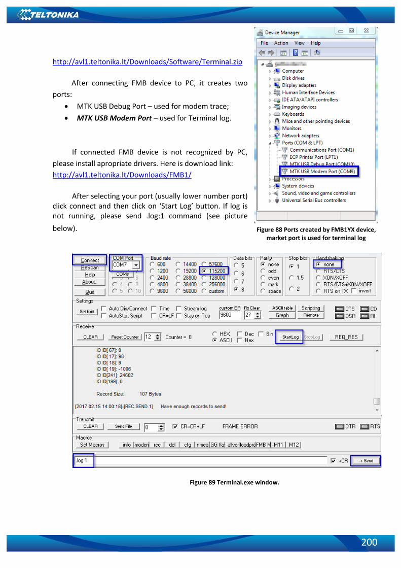
200
http://avl1.teltonika.lt/Downloads/Software/Terminal.zip
After connecting FMB device to PC, it creates two
ports:
• MTK USB Debug Port – used for modem trace;
• MTK USB Modem Port – used for Terminal log.
If connected FMB device is not recognized by PC,
please install apropriate drivers. Here is download link:
http://avl1.teltonika.lt/Downloads/FMB1/
After selecting your port (usually lower number port) click connect and then click on ‘Start Log’ button. If log is not running, please send .log:1 command (see picture
below).
Figure 89 Terminal.exe window.
Figure 88 Ports created by FMB1YX device, market port is used for terminal log
201
13 CHANGE LOG
Nr. Date Version Comments
1 2017-07-17 0.00 Preliminary draft release.
2 2017-07-19 0.01 Preliminary draft release update.
3 2017-08-01 0.02 Added FMB122 and FMB125 devices description.
4 2017-08-02 0.03 Changed Dual Sim functionality description
5 2017-08-02 0.04 Added Navigate LED Behavior: Blinking fast constantly. Added new sms: getvin
6 2017-08-04 0.05 Updated Table 2 (Technical details) and Table 4 (Electrical characteristics tables). Added iButton read notification feature.
7 2017-08-08 0.06
Changed FMB122 Depp Sleep mode energy consumption value. Added FMB120/ FMB122 and FMB125 Online Deep Sleep energy consumption values. Changed FMB125 RS232\RS485 parameters configuration hyperlink name.
8 2017-08-09 0.07 Changed Power supply description.
9 2017-08-09 0.08 Edited Power Voltage, Input, Input Voltage, GNSS description.
10 2017-08-10 0.09 Updated Input voltage and resistance description
11 2017-09-29 0.10 Added weight data