* des idées en action. pws 550 pws 600 kullan∂m k∂lavuzu ... · english - 2 measured values...
TRANSCRIPT
* Des idées en action.
BedienungsanleitungOperating instructionsInstructions d’emploiInstrucciones de servicioManual de instruçõesIstruzioni d’usoGebruiksaanwijzingBetjeningsvejledningBruksanvisningBrukerveiledningenKäyttöohje�δηγία �ειρισµ�ύKullan∂m k∂lavuzu
DeutschEnglishFrançaisEspañolPortuguêsItalianoNederlandsDanskSvenskaNorskSuomiEλληvικάTürkçe
PWS 550PWS 600PWS 6-115PWS 7-100PWS 7-115PWS 7-125PWS 9-125 CE
2 609 000 397.book Seite 1 Donnerstag, 26. August 2004 1:27 13
2 • 2 609 000 397 • 04.08
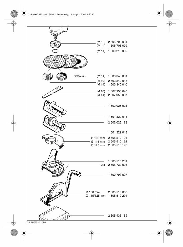
2 605 703 0311 605 703 099
1 600 210 039
1 603 340 031
2 603 340 0181 603 340 040
1 607 950 0402 607 950 037
1 602 025 024
1 601 329 013
1 605 510 2812 605 730 036
1 600 793 007
2 605 510 0661 605 510 291
2 605 438 169
(M 10)(M 14)
(M 14)
(M 14)
(M 10)(M 14)
(M 10)(M 14)
Ø 100 mmØ 115/125 mm
2 x
2 605 510 1912 605 510 1922 605 510 193
Ø 100 mmØ 115 mmØ 125 mm
2 602 025 123
1 601 329 013
2 609 000 397.book Seite 2 Donnerstag, 26. August 2004 1:27 13
3 • 2 609 000 397 • 04.08
2 609 000 397.book Seite 1 Donnerstag, 26. August 2004 1:27 13
4 + 5 • 2 609 000 397 • 04.08
DIA
MO
ND L
aser
66
913
12
16
12
6
14
6
15
3
1
2
54
8
7
6
11
10
11
4
10
18
178
PWS 9-125 CE
2 609 000 397 - U4+5 Seite 4 Donnerstag, 26. August 2004 12:59 12
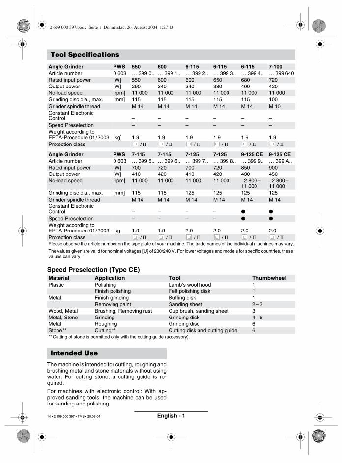
English - 1
Speed Preselection (Type CE)
The machine is intended for cutting, roughing andbrushing metal and stone materials without usingwater. For cutting stone, a cutting guide is re-quired.
For machines with electronic control: With ap-proved sanding tools, the machine can be usedfor sanding and polishing.
Tool Specifications
Angle Grinder PWS 550 600 6-115 6-115 6-115 7-100Article number 0 603 … 399 0.. … 399 1.. … 399 2.. … 399 3.. … 399 4.. … 399 640Rated input power [W] 550 600 600 650 680 720Output power [W] 290 340 340 380 400 420No-load speed [rpm] 11 000 11 000 11 000 11 000 11 000 11 000Grinding disc dia., max. [mm] 115 115 115 115 115 100Grinder spindle thread M 14 M 14 M 14 M 14 M 14 M 10Constant Electronic Control – – – – – –Speed Preselection – – – – – –Weight according to EPTA-Procedure 01/2003 [kg] 1.9 1.9 1.9 1.9 1.9 1.9Protection class / II / II / II / II / II / II
Angle Grinder PWS 7-115 7-115 7-125 7-125 9-125 CE 9-125 CEArticle number 0 603 … 399 5.. … 399 6.. … 399 7.. … 399 8.. … 399 9.. … 399 A..Rated input power [W] 700 720 700 720 850 900Output power [W] 410 420 410 420 430 450No-load speed [rpm] 11 000 11 000 11 000 11 000 2 800 –
11 0002 800 –
11 000Grinding disc dia., max. [mm] 115 115 125 125 125 125Grinder spindle thread M 14 M 14 M 14 M 14 M 14 M 14Constant Electronic Control – – – – ● ●
Speed Preselection – – – – ● ●
Weight according to EPTA-Procedure 01/2003 [kg] 1.9 1.9 2.0 2.0 2.0 2.0Protection class / II / II / II / II / II / IIPlease observe the article number on the type plate of your machine. The trade names of the individual machines may vary.
The values given are valid for nominal voltages [U] of 230/240 V. For lower voltages and models for specific countries, these values can vary.
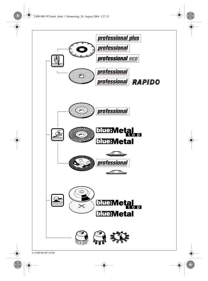
Material Application Tool ThumbwheelPlastic Polishing Lamb’s wool hood 1
Finish polishing Felt polishing disk 1Metal Finish grinding Buffing disk 1
Removing paint Sanding sheet 2 – 3Wood, Metal Brushing, Removing rust Cup brush, sanding sheet 3Metal, Stone Grinding Grinding disk 4 – 6Metal Roughing Grinding disc 6Stone** Cutting** Cutting disk and cutting guide 6** Cutting of stone is permitted only with the cutting guide (accessory).
Intended Use
2 609 000 397.book Seite 1 Donnerstag, 26. August 2004 1:27 13
14 • 2 609 000 397 • TMS • 20.08.04
English - 2
Measured values determined according toEN 50 144.
Typically the A-weighted noise levels of the ma-chine are: Sound pressure level: 88 dB (A);sound power level: 101 dB (A).Wear hearing protection!When using the standard auxiliary handle, thetypically weighted maximum acceleration is5.3 m/s2.
When using the vibration-dampening auxiliaryhandle, the typically weighted maximum acceler-ation is 5.3 m/s2. The hand-arm vibration at theauxiliary handle is typically lower than 2.5 m/s2.
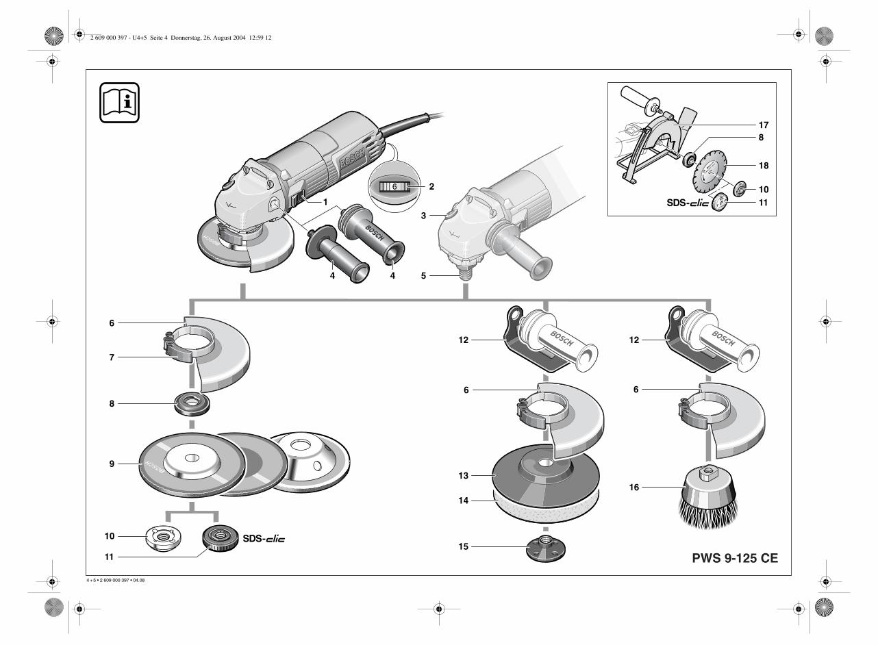
The numbering of the machine elements refers tothe illustration of the machine on the graphicspage.
While reading the operating instructions, unfoldthe graphics page for the machine and leave itopen.
1 On/Off switch
2 Thumbwheel for speed preselection(PWS 9-125 CE)
3 Spindle lock button
4 Auxiliary handle
5 Grinder spindle
6 Protection guard
7 Clamping lever
8 Mounting flange(for the M 14 grinding spindle with O-ring)
9 Grinding-/cutting disc*
10 Clamping nut
11 quick-clamping nut*
12 Hand guard*
13 Rubber sanding plate*
14 Sanding sheet*
15 Round nut*
16 Cup brush*
17 Cutting guide with dust extraction protection guard*
18 Diamond cutting disc*
19 Mounting flange M 10* Not all of the accessories illustrated or described are
included as standard delivery.
Working safely with this ma-chine is possible only when theoperating and safety informationare read completely and the in-structions contained therein arestrictly followed. In addition, the
general safety notes in the enclosed bookletmust be observed. Before using for the firsttime, ask for a practical demonstration.■ Wear protective glasses and hearing protec-
tion.
■ Wear additional protection equipment for yoursafety, such as protective gloves, sturdyshoes, hard hat and apron.
■ The dust that is produced while working can bedetrimental to health, inflammable or explo-sive. Suitable safety measures are required.Examples: Some dusts are regarded as carci-nogenic. Use suitable dust/chip extraction andwear a dust protection mask.
■ Dust from light alloys can burn or explode. Al-ways keep the workplace clean, as blends ofmaterials are particularly dangerous.
■ If the mains cable is damaged or cut throughwhile working, do not touch the cable but im-mediately pull the mains plug. Never use themachine with a damaged cable.
■ Connect machines that are used in the openvia a residual current device (RCD) with an ac-tuating current of 30 mA maximum. Do not op-erate the machine in rain or moisture.
■ When working with the machine, always hold itfirmly with both hands and provide for a securestance.
■ Secure the workpiece. A workpiece clampedwith clamping devices or in a vice is held moresecurely than by hand.
■ Always direct the cable to the rear away fromthe machine.
■ Always switch the machine off and wait until ithas come to a standstill before placing it down.
■ For power outage or when the mains plug ispulled, unlock the On/Off switch immediatelyand turn it to the Off position. This prevents un-controlled restarting.
■ The machine must be used only for dry cutting/grinding.
■ For all work with the machine, the auxiliaryhandle must be mounted.
Noise/Vibration Information
Machine Elements
For Your Safety
2 609 000 397.book Seite 2 Donnerstag, 26. August 2004 1:27 13
15 • 2 609 000 397 • TMS • 20.08.04
English - 3
■ When performing an operation where thetool insert can run into concealed electriclines, hold the machine by the insulatedhandles only.Contact with a “live” wire will make exposedmetal parts of the tool “live” and shock the op-erator.
■ Use suitable detectors to determine if util-ity lines are hidden in the work area or callthe local utility company for assistance.Contact with electric lines can lead to fire andelectric shock. Damaging a gas line can leadto explosion. Penetrating a water line causesproperty damage or may cause an electricshock.
■ For work with grinding or cutting discs, the pro-tection guard 6 must be mounted. For workwith the rubber sanding plate 13 or with thecup brush 16/disc brush/flap disc, the handguard 12 (accessory) is to be mounted.
■ Use dust extraction when working with stone.The vacuum cleaner must be approved for ma-sonry dust. When cutting stone, use the cuttingguide.
■ Do not work with materials containing asbes-tos.
■ Use only grinding tools with a permissiblespeed at least as high as the no-load speed ofthe machine.
■ Check grinding tools before use. The grindingtool must be properly mounted and turn freely.Perform a test run for at least 30 seconds with-out load. Do not use damaged, out-of-round orvibrating grinding tools.
■ Protect the grinding tool from impact, shockand grease.
■ Apply the machine to the workpiece only whenswitched on.
■ Keep hands away from rotating grinding tools.
■ Pay attention to the direction of rotation. Al-ways hold the machine so that sparks andgrinding dust fly away from the body.
■ When grinding metal, flying sparks are pro-duced. Take care that no persons are endan-gered. Due to danger of fire, no combustiblematerials should be located in the vicinity(spark flight zone).
■ Be careful when cutting grooves, e. g. in struc-tural walls: See Information on Structures.
■ Blocking the cutting disc leads to jerking reac-tion forces on the machine. In this case switchoff the machine immediately.
■ Observe the dimensions of the grinding discs.The hole diameter must fit mountingflange 8 (M 14), 19 (M 10). Do not use any re-ducers or adapters.
■ Never use cutting discs for rough grinding. Donot exert any lateral pressure on the cuttingdiscs.
■ Observe the manufacturer’s instructions formounting and using grinding tools.
■ Caution! The grinding tool runs on after themachine is switched off.
■ Do not clamp the machine in a vice.
■ Never allow children to use the machine.
■ Bosch is only able to ensure perfect operationof the machine if the original accessories in-tended for it are used.
Slots in structural walls are subject to the Stand-ard DIN 1053, Part 1 or country-specific regula-tions.
These regulations are to be observed under allcircumstances. Before beginning work, consultthe responsible structural engineer, architect orthe construction supervisor.
Information on Structures
2 609 000 397.book Seite 3 Donnerstag, 26. August 2004 1:27 13
16 • 2 609 000 397 • TMS • 20.08.04
English - 4
■ Before any work on the machine itself, pull themains plug.
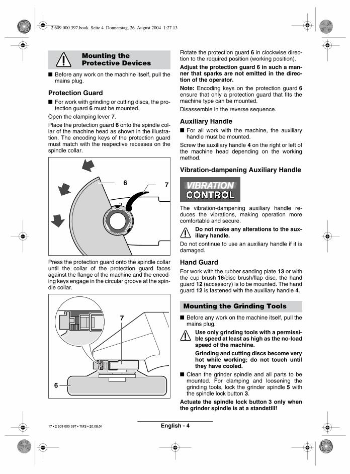
Protection Guard■ For work with grinding or cutting discs, the pro-
tection guard 6 must be mounted.
Open the clamping lever 7.
Place the protection guard 6 onto the spindle col-lar of the machine head as shown in the illustra-tion. The encoding keys of the protection guardmust match with the respective recesses on thespindle collar.
Press the protection guard onto the spindle collaruntil the collar of the protection guard facesagainst the flange of the machine and the encod-ing keys engage in the circular groove at the spin-dle collar.
Rotate the protection guard 6 in clockwise direc-tion to the required position (working position).
Adjust the protection guard 6 in such a man-ner that sparks are not emitted in the direc-tion of the operator.Note: Encoding keys on the protection guard 6ensure that only a protection guard that fits themachine type can be mounted.
Disassemble in the reverse sequence.
Auxiliary Handle■ For all work with the machine, the auxiliary
handle must be mounted.
Screw the auxiliary handle 4 on the right or left ofthe machine head depending on the workingmethod.
Vibration-dampening Auxiliary Handle
The vibration-dampening auxiliary handle re-duces the vibrations, making operation morecomfortable and secure.
Do not make any alterations to the aux-iliary handle.
Do not continue to use an auxiliary handle if it isdamaged.
Hand GuardFor work with the rubber sanding plate 13 or withthe cup brush 16/disc brush/flap disc, the handguard 12 (accessory) is to be mounted. The handguard 12 is fastened with the auxiliary handle 4.
■ Before any work on the machine itself, pull themains plug.
Use only grinding tools with a permissi-ble speed at least as high as the no-loadspeed of the machine.Grinding and cutting discs become veryhot while working; do not touch untilthey have cooled.
■ Clean the grinder spindle and all parts to bemounted. For clamping and loosening thegrinding tools, lock the grinder spindle 5 withthe spindle lock button 3.
Actuate the spindle lock button 3 only whenthe grinder spindle is at a standstill!
Mounting the Protective Devices
6 7
6
7
Mounting the Grinding Tools
2 609 000 397.book Seite 4 Donnerstag, 26. August 2004 1:27 13
17 • 2 609 000 397 • TMS • 20.08.04
English - 5
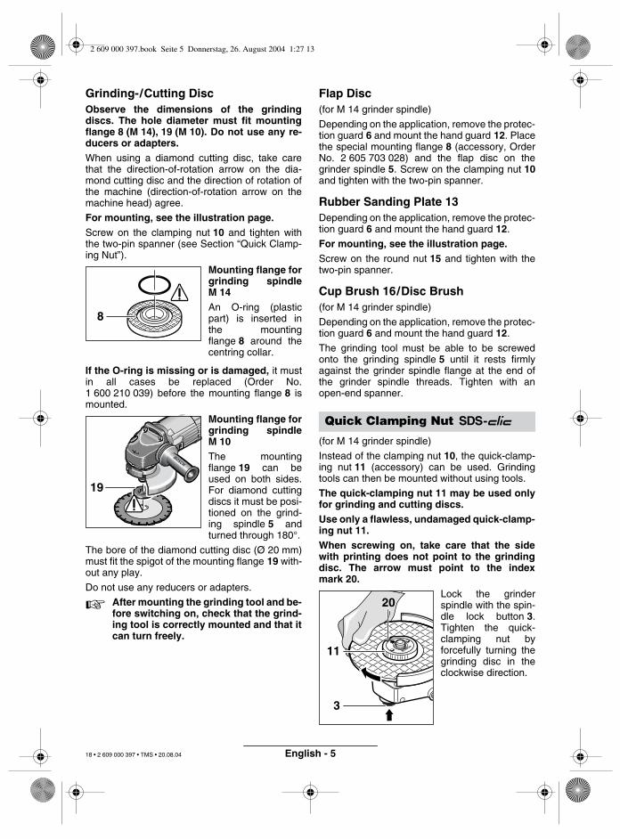
Grinding-/Cutting DiscObserve the dimensions of the grindingdiscs. The hole diameter must fit mountingflange 8 (M 14), 19 (M 10). Do not use any re-ducers or adapters.When using a diamond cutting disc, take carethat the direction-of-rotation arrow on the dia-mond cutting disc and the direction of rotation ofthe machine (direction-of-rotation arrow on themachine head) agree.
For mounting, see the illustration page.Screw on the clamping nut 10 and tighten withthe two-pin spanner (see Section “Quick Clamp-ing Nut”).
Mounting flange forgrinding spindleM 14An O-ring (plasticpart) is inserted inthe mountingflange 8 around thecentring collar.
If the O-ring is missing or is damaged, it mustin all cases be replaced (Order No.1 600 210 039) before the mounting flange 8 ismounted.
Mounting flange forgrinding spindleM 10The mountingflange 19 can beused on both sides.For diamond cuttingdiscs it must be posi-tioned on the grind-ing spindle 5 andturned through 180°.
The bore of the diamond cutting disc (Ø 20 mm)must fit the spigot of the mounting flange 19 with-out any play.
Do not use any reducers or adapters.
☞ After mounting the grinding tool and be-fore switching on, check that the grind-ing tool is correctly mounted and that itcan turn freely.
Flap Disc(for M 14 grinder spindle)
Depending on the application, remove the protec-tion guard 6 and mount the hand guard 12. Placethe special mounting flange 8 (accessory, OrderNo. 2 605 703 028) and the flap disc on thegrinder spindle 5. Screw on the clamping nut 10and tighten with the two-pin spanner.
Rubber Sanding Plate 13Depending on the application, remove the protec-tion guard 6 and mount the hand guard 12.
For mounting, see the illustration page.Screw on the round nut 15 and tighten with thetwo-pin spanner.
Cup Brush 16/Disc Brush(for M 14 grinder spindle)
Depending on the application, remove the protec-tion guard 6 and mount the hand guard 12.
The grinding tool must be able to be screwedonto the grinding spindle 5 until it rests firmlyagainst the grinder spindle flange at the end ofthe grinder spindle threads. Tighten with anopen-end spanner.
(for M 14 grinder spindle)
Instead of the clamping nut 10, the quick-clamp-ing nut 11 (accessory) can be used. Grindingtools can then be mounted without using tools.
The quick-clamping nut 11 may be used onlyfor grinding and cutting discs.Use only a flawless, undamaged quick-clamp-ing nut 11.When screwing on, take care that the sidewith printing does not point to the grindingdisc. The arrow must point to the indexmark 20.
Lock the grinderspindle with the spin-dle lock button 3.Tighten the quick-clamping nut byforcefully turning thegrinding disc in theclockwise direction.
8
19
Quick Clamping Nut
3
20
11
2 609 000 397.book Seite 5 Donnerstag, 26. August 2004 1:27 13
18 • 2 609 000 397 • TMS • 20.08.04
English - 6
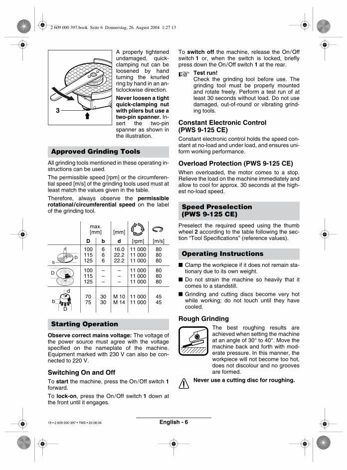
A properly tightenedundamaged, quick-clamping nut can beloosened by handturning the knurledring by hand in an an-ticlockwise direction.
Never loosen a tightquick-clamping nutwith pliers but use atwo-pin spanner. In-sert the two-pinspanner as shown inthe illustration.
All grinding tools mentioned in these operating in-structions can be used.
The permissible speed [rpm] or the circumferen-tial speed [m/s] of the grinding tools used must atleast match the values given in the table.
Therefore, always observe the permissiblerotational/circumferential speed on the labelof the grinding tool.
Observe correct mains voltage: The voltage ofthe power source must agree with the voltagespecified on the nameplate of the machine.Equipment marked with 230 V can also be con-nected to 220 V.
Switching On and OffTo start the machine, press the On/Off switch 1forward.
To lock-on, press the On/Off switch 1 down atthe front until it engages.
To switch off the machine, release the On/Offswitch 1 or, when the switch is locked, brieflypress down the On/Off switch 1 at the rear.
☞ Test run!Check the grinding tool before use. Thegrinding tool must be properly mountedand rotate freely. Perform a test run of atleast 30 seconds without load. Do not usedamaged, out-of-round or vibrating grind-ing tools.
Constant Electronic Control(PWS 9-125 CE)Constant electronic control holds the speed con-stant at no-load and under load, and ensures uni-form working performance.
Overload Protection (PWS 9-125 CE)When overloaded, the motor comes to a stop.Relieve the load on the machine immediately andallow to cool for approx. 30 seconds at the high-est no-load speed.
Preselect the required speed using the thumbwheel 2 according to the table following the sec-tion “Tool Specifications” (reference values).
■ Clamp the workpiece if it does not remain sta-tionary due to its own weight.
■ Do not strain the machine so heavily that itcomes to a standstill.
■ Grinding and cutting discs become very hotwhile working; do not touch until they havecooled.
Rough GrindingThe best roughing results areachieved when setting the machineat an angle of 30° to 40°. Move themachine back and forth with mod-erate pressure. In this manner, theworkpiece will not become too hot,does not discolour and no groovesare formed.
Never use a cutting disc for roughing.
Approved Grinding Tools
max.[mm] [mm]
D b d [rpm] [m/s]
100115125
666
16.022.222.2
11 00011 00011 000
808080
100115125
–––
–––
11 00011 00011 000
808080
7075
3030
M 10M 14
11 00011 000
4545
Starting Operation
3
b
d
D
D
D
b
d
Speed Preselection(PWS 9-125 CE)
Operating Instructions
2 609 000 397.book Seite 6 Donnerstag, 26. August 2004 1:27 13
19 • 2 609 000 397 • TMS • 20.08.04
English - 7
Flap DiscWith the flap disc (accessory), curved surfacesand profiles (contour sanding) can be worked.
Flap discs have a considerably higher service lifethan sanding sheets, lower noise level and lowersanding temperatures.
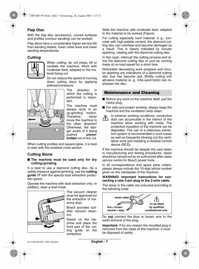
CuttingWhen cutting, do not press, tilt oroscillate the machine. Work withmoderate feed, adapted to the ma-terial being cut.
Do not reduce the speed of runningdown cutting discs by applyingsideward pressure.
The direction inwhich the cutting isperformed is impor-tant.
The machine mustalways work in anup-grinding motion.Therefore, nevermove the machine inthe other direction!Otherwise, the dan-ger exists of it beingpushed uncon-trolled out of the cut.
When cutting profiles and square pipes, it is bestto start with the smallest cross section.
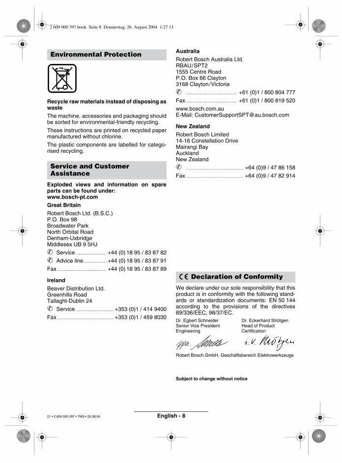
Cutting Stone■ The machine must be used only for dry
cutting/grinding.It is best to use a diamond cutting disc. As asafety measure against jamming, use the cuttingguide 17 with the special dust extraction protec-tion guard.
Operate the machine with dust extraction only. Inaddition, wear a dust mask.
The vacuum cleanermust be approved forthe extraction of ma-sonry dust.
Bosch provides suit-able vacuum clean-ers.
Switch on the ma-chine and place thefront part of the cut-ting guide on theworkpiece.
Slide the machine with moderate feed, adaptedto the material to be worked (Figure).
For cutting especially hard material, e. g., con-crete with high pebble content, the diamond cut-ting disc can overheat and become damaged asa result. This is clearly indicated by circularsparking, rotating with the diamond cutting disc.
In this case, interrupt the cutting process and al-low the diamond cutting disc to cool by runningfreely at no-load speed for a short time.
Noticeable decreasing work progress and circu-lar sparking are indications of a diamond cuttingdisc that has become dull. Briefly cutting intoabrasive material (e. g., lime-sand brick) can re-sharpen the disc.
■ Before any work on the machine itself, pull themains plug.
■ For safe and proper working, always keep themachine and the ventilation slots clean.
In extreme working conditions, conductivedust can accumulate in the interior of themachine when working with metal. Theprotective insulation of the machine can bedegraded. The use of a stationary extrac-tion system is recommended in such casesas well as frequently blowing out the venti-lation slots and installing a residual currentdevice (RCD).
If the machine should fail despite the care takenin manufacturing and testing procedures, repairshould be carried out by an authorized after-salesservice centre for Bosch power tools.
In all correspondence and spare parts orders,please always include the 10-digit article numbergiven on the nameplate of the machine.
WARNING! Important instructions for con-necting a new 3-pin plug to the 2-wire cable.The wires in the cable are coloured according tothe following code:
Do not connect the blue or brown wire to theearth terminal of the plug.
Important: If for any reason the moulded plug is removed from the cable of this machine, it must be disposed of safely.
Maintenance and Cleaning
strain relief
live = brownneutral = blue
To be fittedby qualified
professional only
2 609 000 397.book Seite 7 Donnerstag, 26. August 2004 1:27 13
20 • 2 609 000 397 • TMS • 20.08.04
English - 8
Recycle raw materials instead of disposing aswasteThe machine, accessories and packaging shouldbe sorted for environmental-friendly recycling.
These instructions are printed on recycled papermanufactured without chlorine.
The plastic components are labelled for catego-rised recycling.
Exploded views and information on spareparts can be found under:www.bosch-pt.comGreat BritainRobert Bosch Ltd. (B.S.C.)P.O. Box 98Broadwater ParkNorth Orbital RoadDenham-UxbridgeMiddlesex UB 9 5HJ
✆ Service ............................ +44 (0) 18 95 / 83 87 82
✆ Advice line .................... +44 (0) 18 95 / 83 87 91
Fax ............................................. +44 (0) 18 95 / 83 87 89
IrelandBeaver Distribution Ltd.Greenhills RoadTallaght-Dublin 24
✆ Service ................................... +353 (0)1 / 414 9400
Fax .................................................... +353 (0)1 / 459 8030
AustraliaRobert Bosch Australia Ltd.RBAU/SPT2 1555 Centre Road P.O. Box 66 Clayton 3168 Clayton/Victoria
✆ ............................................... +61 (0)1 / 800 804 777
Fax............................................... +61 (0)1 / 800 819 520
www.bosch.com.auE-Mail: [email protected]
New ZealandRobert Bosch Limited 14-16 Constellation DriveMairangi BayAucklandNew Zealand
✆ ..................................................... +64 (0)9 / 47 86 158
Fax..................................................... +64 (0)9 / 47 82 914
We declare under our sole responsibility that thisproduct is in conformity with the following stand-ards or standardization documents: EN 50 144according to the provisions of the directives89/336/EEC, 98/37/EC.Dr. Egbert Schneider Dr. Eckerhard StrötgenSenior Vice President Head of ProductEngineering Certification
Robert Bosch GmbH, Geschäftsbereich Elektrowerkzeuge
Subject to change without notice
Environmental Protection
Service and Customer Assistance
Declaration of Conformity
2 609 000 397.book Seite 8 Donnerstag, 26. August 2004 1:27 13
21 • 2 609 000 397 • TMS • 20.08.04
Robert Bosch GmbHGeschäftsbereich Elektrowerkzeuge70745 Leinfelden-Echterdingen
www.bosch-pt.com
2 609 000 397 (04.08) O / 113
Printed in Hungary - Imprimé en Hongrie
Chlor
* Des idées en action.
2 609 000 397.book Seite 1 Donnerstag, 26. August 2004 1:27 13