urlnrl.northumbria.ac.uk/26881/1/id#1667.pdf · · 2017-11-29and construction engineering...
TRANSCRIPT
Citation: Righetti, Luca, Edmondson, Vikki, Corradi, Marco and Borri, Antonio (2016) Behaviour of small masonry assemblages reinforced with a steel cord reinforced joint repointing. In: 16th International Conference on Structural Faults and Repair, 17-19 May 2016, Edinburgh.
URL:
This version was downloaded from Northumbria Research Link: http://nrl.northumbria.ac.uk/26881/
Northumbria University has developed Northumbria Research Link (NRL) to enable users to access the University’s research output. Copyright © and moral rights for items on NRL are retained by the individual author(s) and/or other copyright owners. Single copies of full items can be reproduced, displayed or performed, and given to third parties in any format or medium for personal research or study, educational, or not-for-profit purposes without prior permission or charge, provided the authors, title and full bibliographic details are given, as well as a hyperlink and/or URL to the original metadata page. The content must not be changed in any way. Full items must not be sold commercially in any format or medium without formal permission of the copyright holder. The full policy is available online: http://nrl.northumbria.ac.uk/policies.html
This document may differ from the final, published version of the research and has been made available online in accordance with publisher policies. To read and/or cite from the published version of the research, please visit the publisher’s website (a subscription may be required.)
BEHAVIOUR OF SMALL MASONRY ASSEMBLAGES REINFORCED WITH A
STEEL CORD REINFORCED JOINT REPOINTING
Luca Righetti, Vikki Edmondson &
Dr Marco Corradi
Dept of Mechanical
and Construction Engineering
Northumbria University
Wynne-Jones Building, NE1 8ST
Newcastle upon Tyne (UK)
Prof Antonio Borri
Dept of Engineering
University of Perugia
Via Duranti 93, 06125
Perugia (Italy)
KEYWORDS: Brick masonry; Bed joint reinforcement; Repointing; Steel cords.
ABSTRACT: Unreinforced masonry (URM) walls are one of the oldest and most common types of
construction elements in the world. However they are susceptible to failure when exposed to overstresses,
caused by out-of-plane and in-plane loads. In this paper a new method for reinforcing brickwork masonry
using steel cords embedded into the mortar joints is proposed. The average cord diameter of 3 mm, enables
reinforcement to be retrofitted to brick and irregular stone-masonry walls. Joints can then be repointed to
hide the cords, so that no evidence of strengthening work is visible on the final finished façade. The
bending behaviour of 20 brick-masonry small assemblages has been evaluated. Specimens have been
prepared using two courses of bricks with nominal dimensions of 215 x 102 x 65 mm and two different
types of lime-based mortar. After the mechanical characterization of the materials used for construction
and reinforcement, an experimental was carried out to assess the potential of the technique comparing the
results of bending test achieved for unreinforced specimens. Test results show an increase of bending
capacity and of flexural stiffness up to 49.8 and 475%, respectively.
INTRODUCTION
Masonry is a construction material manufactured as combination of components (stones, bricks or blocks)
laid in a cementitious or lime-based mortar and usually arranged in a regular way. Despite of its simplicity
of construction, the study and analysis of the mechanical behaviour of masonry structures remains a
challenge for researchers and engineers. Masonry is a heterogeneous and anisotropic material. The
presence of mortar joints creates resistance to tensile stress, although it is noticeably less than the resistance
to compression.
Historic masonry buildings were designed to resist mainly gravity loads with no attention to the actions
caused by a seismic event. In general earthquakes introduce in-plane and out-of-plane loads to unreinforced
walls. Typical damage suffered by these buildings varies from minor cracking to catastrophic failure. In the
last decades numerous seismic events in southern Europe have emphasized the vulnerability of the masonry
buildings (Bayraktar et al; 2007), (Corradi et al; 2011), (D’Ayala and Paganoni; 2011), (Brandonisio et al.;
2013). Because these buildings constitute a large part of the European building heritage, a process of
structural strengthening is often necessary in order to increase the service life and improve their seismic
capability.
Some of the most known traditional strengthening methods used to upgrade the mechanical behaviour of
unreinforced masonry buildings are:grout injections used to fill voids and cracks in the damaged masonry
assemblages (Schuller et al.; 1994), (Vintzileou and Tassios; 1995), (Binda et al.; 1997); steel-mesh
jackting which constitutes of a thin coatings of cement plaster over a steel mesh (Jabarov et al.; 1980),
(Sheppard and Tercely; 1980) and ferrocement which is realized applying onto one or both external
surfaces of the wall reinforced cement or concrete layers (Prawel et al. 1988).
However these traditional strengthening techniques sometimes have not led to the expected results in term
of efficiency (Valluzzi, 2007), (Corradi et al.; 2008) because sometimes they increased the mass of the
structure which increase the earthquake induced inertia forces (Gilstrap and Dolan; 1998). These problems
have been overcome by using Fibre Reinforced Polymer (FRP) materials as a replacement for the
conventional methods. In the last three decades, FRPs have been used extensively as reinforcement
materials for unreinforced masonry panels (Bakis et al.; 2002), because of their characteristics:high-
strength, light-weight and low costs availability. FRPs strips or laminates have been externally applied
directly on the unreinforced elements in order to increase their shear strength (Triantafillou; 1998),
(Valluzzi et al.; 2002), (Roca and Araiza; 2010). However, heritage conservation authorities have prepared
guidance which restrictions in the use of these techniques in historic-monumental building, due to the
irreversibility of the intervention and the alteration of the external aesthetic facades of the structures
(Papanicoulau et al.; 2008). Other studies addressed the strengthening of the mortar bed joints, the
technique consists by removing the superficial mortar and then by repointing the joints with reinforcement
elements (steel plate, FRP laminates or bars) and new good quality mortar. D’Ayala (1998) proposed a
strengthening intervention on an existing masonry building by inserting steel thin plates into the bed joints
in order to reduce the cracking associated with bending failures. Valluzzi et al. (2005) carried out and
experimental campaign on masonry walls by inserting two steel bars, 6 mm in diameter, and repointing
them with hydraulic lime mortar or polymeric resin. The previous technique was applied also in two
existing historical masonry buildings (St. Giustina’s bell tower and St. Sofia’s church). Borri et al. (2013)
investigated the behaviour of small masonry columns with four different cross sections reinforced with pre-
tensioned steel cords embedded into the horizontal bed-joints.
In earlier studies some of the Authors proposed a system known as ‘Reticolatus’, which involves inserting
into the mortar joints of masonry a continuous mesh of thin high strength stainless steel cords (Corradi et
al.; 2010), (Borri et al., 2014). With the aim to further investigate the mechanical behavior of this
reinforcing technique, this paper presents the result of an experimental investigation on the use of high
strength steel cords used to improve the bending behaviour of small brick masonry panels. Specimens have
been prepared using five solid bricks with only one horizontal mortar bed joint. Masonry units have been
overlapped on alternate courses and two different hydraulic lime-based mortars have been used. The
reinforcing technique is based on the insertion of steel cords in the mortar bed joints previously partially
cleared out and then refilled with new mortar.
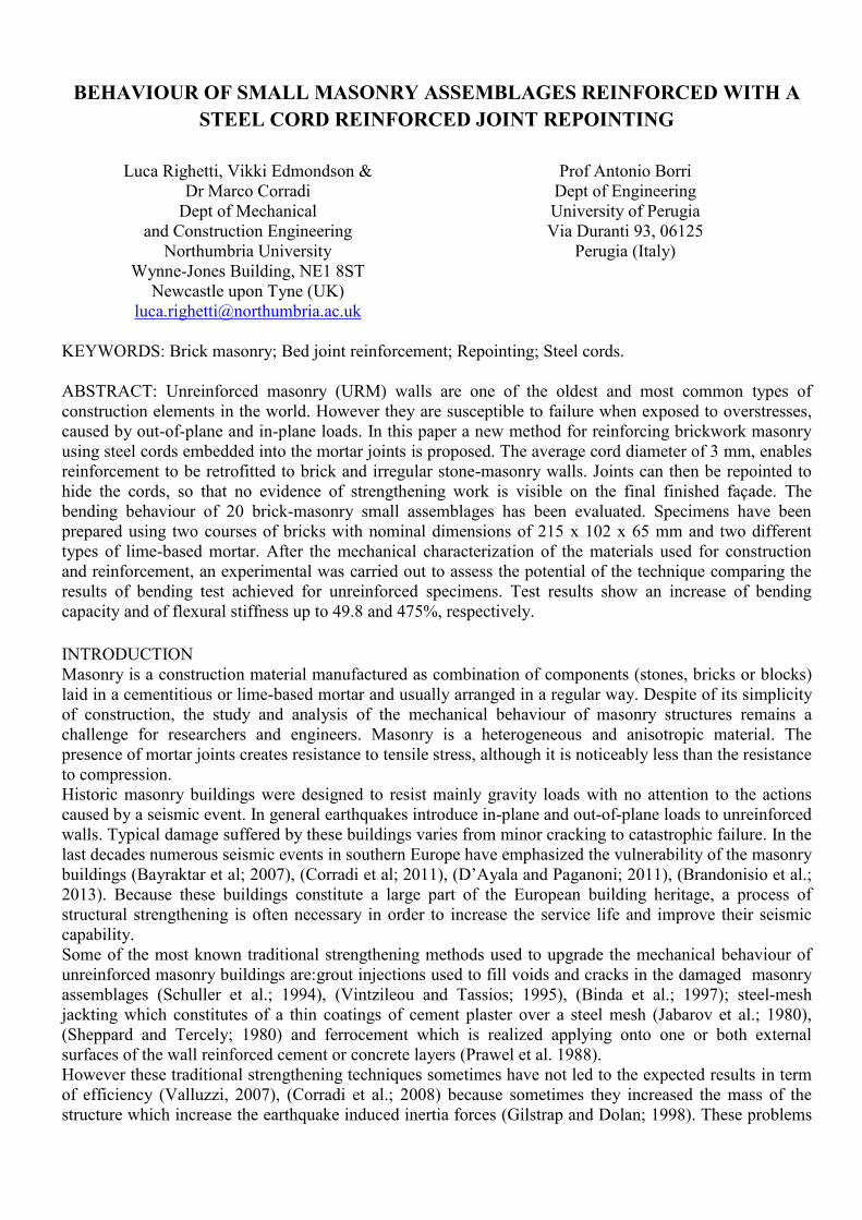
STRENGTHENING TECHNIQUE DESCRIPTION The bed joint strengthening technique consists of inserting a high strength steel cord in the mortar bed joint previously raked out by a few (approx. 10 mm) millimeters and repointing with new mortar. It is mainly suitable for masonry characterized by regular courses and is more effective if realized on both sides of the wall. However it can be also applied on stonemasonry wall panels (Fig. 1). In order to apply the reinforcement on existing masonry walls the following stages are necessary:
Remove any render finishing or plaster from the wall’s surface;
Fig. 1: Mechanical behavior of the reinforcement.
Fig.2: Rake out the horizontal mortar joints.
Void realized
in the
horizontal
mortar jointSteel
cords

Rake out the horizontal mortar joints using appropriate tools (Fig. 2), the excavation should be 10-
15 mm deep, with the width dependent on the material used to reinforce the masonry wall and the
original dimensions of the joints;
Air-jet clean the bed joints to remove powder and small debrises;
Place a first layer of repointing material (mortar);
Apply the reinforcing materials (steel cord) in the raked residual voids (Figs. 3-4);
Place a final layer of repointing material to cover the reinforcing material and restore the original
aspect of the wall.
Fig. 3: Detail of the reinforcing technique.
Fig. 4: Example of the application of the
reinforcement technique: the indoor façade
could be reinforced with a more traditional steel-
mesh jacketing or the proposed technique.
MATERIALS CHARACTERIZATION
(1) Bricks
Solid clay units, with nominal dimensions 215 x 102 x 65 mm, have been used for the construction of the
masonry specimens (Fig. 5). The compressive strength of the masonry units has been evaluated in
according with EN 772-1:2011 standard. Uniaxial compression tests have been carried out on six
specimens. Test results showed a mean compressive strength of 121.01 N/mm2 (Standard deviation (SD) =
9.36 N/mm2).
Fig. 5: Bricks used for construction of specimens.
Fig. 6: Bending test on mortar specimen.
(2) Mortars
The masonry assemblages have been prepared using two different lime-based mortars. The mortar type A
has a ratio sand/binder = 2/1 in volume while type B is made with a ratio sand/binder = 3/2 in volume. In
order to characterize the two mortars, bending and compression tests (Fig. 6) have been performed in
according with EN 1015-11:1999 standard. Three 160 x 40 x 40 mm rectangular prisms have been tested in
three-point bending and in compression. Specimens have been cured for 28 days at room temperature and
test results are reported in Table 1.
Repointing material
Void realized
in the
horizontal
mortar joint
Reinforcing
material
Existing mortar
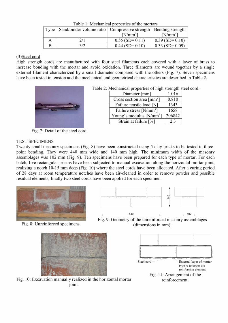
Table 1: Mechanical properties of the mortars
Type Sand/binder volume ratio Compressive strength
[N/mm2]
Bending strength
[N/mm2]
A 2/1 0.55 (SD= 0.11) 0.39 (SD= 0.10)
B 3/2 0.44 (SD= 0.10) 0.33 (SD= 0.09)
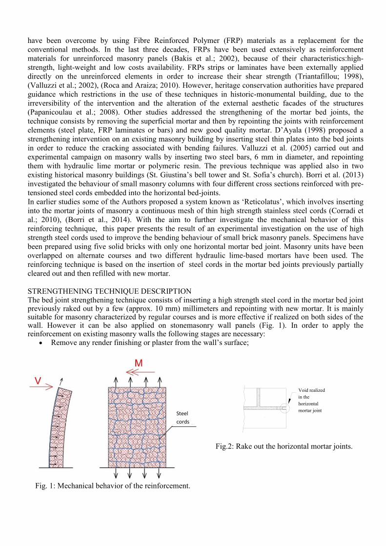
(3)Steel cord
High strength cords are manufactured with four steel filaments each covered with a layer of brass to
increase bonding with the mortar and avoid oxidation. Three filaments are wound together by a single
external filament characterized by a small diameter compared with the others (Fig. 7). Seven specimens
have been tested in tension and the mechanical and geometrical characteristics are described in Table 2.
Fig. 7: Detail of the steel cord.
Table 2: Mechanical properties of high strength steel cord.
Diameter [mm] 1.016
Cross section area [mm2] 0.810
Failure tensile load [N] 1343
Failure stress [N/mm2] 1658
Young’s modulus [N/mm2] 206842
Strain at failure [%] 2.3
TEST SPECIMENS
Twenty small masonry specimens (Fig. 8) have been constructed using 5 clay bricks to be tested in three-
point bending. They were 440 mm wide and 140 mm high. The minimum width of the masonry
assemblages was 102 mm (Fig. 9). Ten specimens have been prepared for each type of mortar. For each
batch, five rectangular prisms have been subjected to manual excavation along the horizontal mortar joint,
realizing a notch 10-15 mm deep (Fig. 10) where the steel cords have been allocated. After a curing period
of 28 days at room temperature notches have been air-cleaned in order to remove powder and possible
residual elements, finally two steel cords have been applied for each specimen.
Fig. 8: Unreinforced specimens.
Fig. 9: Geometry of the unreinforced masonry assemblages
(dimensions in mm).
Fig. 10: Excavation manually realized in the horizontal mortar
joint.
Fig. 11: Arrangement of the
reinforcement.
102
140
440
External layer of mortar
type A to cover the
reinforcing element
Steel cord
Each cords length was approximately 980 mm to allow the tightening and overlap cord ends. Finally, a
layer of mortar type A has been applied to cover the reinforcing cord and restoring the original pointed
finish of the horizontal joints of the masonry assemblages (Fig. 11). Reinforcement was applied on both
sides of the walls. Table 3 shows the test matrix. Each specimen is identified by an alphanumeric index:
the first letter indicates if the sample is unreinforced (U) or reinforced (R), the second the mortar type (A
or B) according with the material characterization and the third a progressive number (from 1 to 5).
Table 3: Test matrix.
Index Mortar used for specimen construction
(Sand/binder volume ratio)
Reinforced
UA_series 2/1 No
UB_series 3/2 No
RA_series 2/1 Yes
RB_series 3/2 Yes
The bending stiffness k has been evaluated using:
)(
1.04.0
maxmax 1.04.0
maxmax
FF dd
FFk
(1)
Where: Fmax is the maximum load and d0.4Fmax and d0.1Fmax are the corresponding mid-span deflections at 40%
and 10% of Fmax.
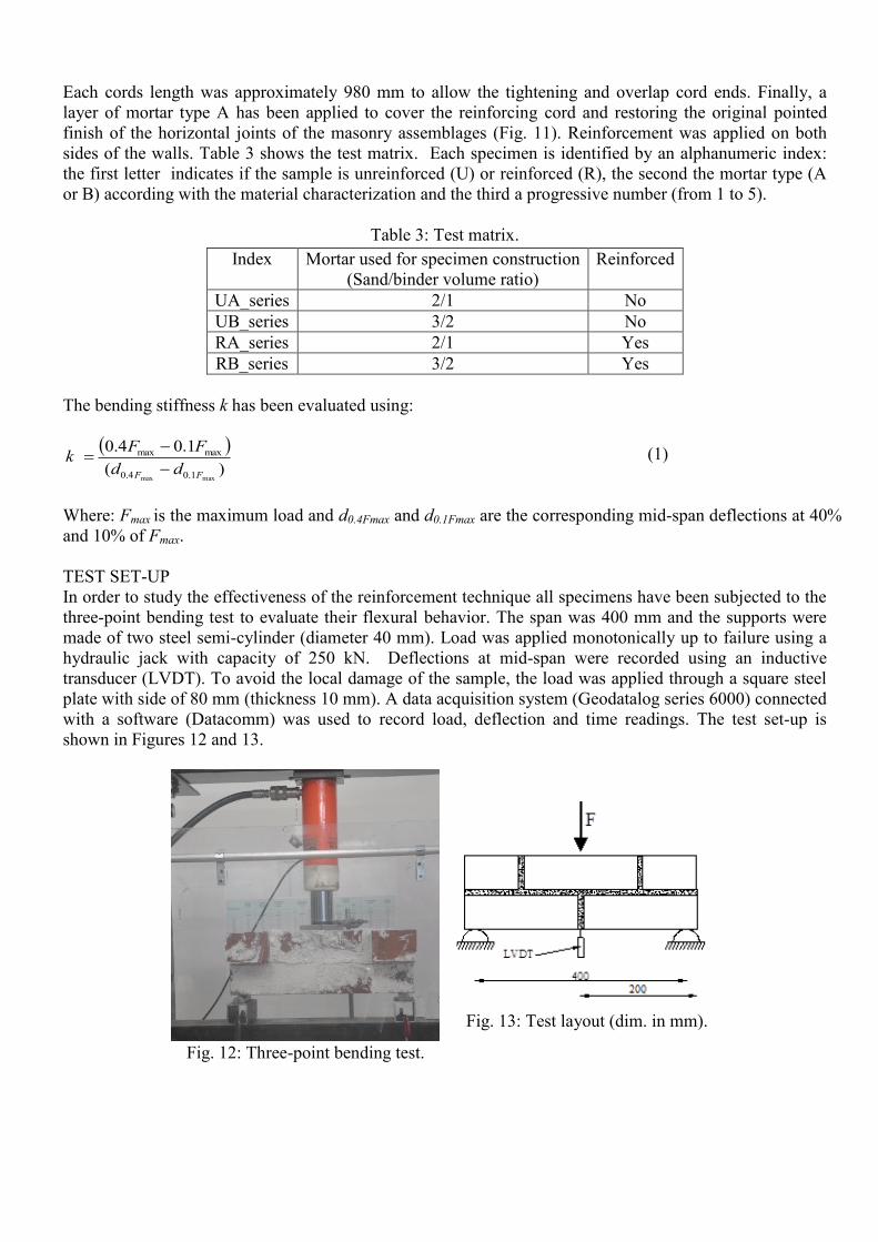
TEST SET-UP
In order to study the effectiveness of the reinforcement technique all specimens have been subjected to the
three-point bending test to evaluate their flexural behavior. The span was 400 mm and the supports were
made of two steel semi-cylinder (diameter 40 mm). Load was applied monotonically up to failure using a
hydraulic jack with capacity of 250 kN. Deflections at mid-span were recorded using an inductive
transducer (LVDT). To avoid the local damage of the sample, the load was applied through a square steel
plate with side of 80 mm (thickness 10 mm). A data acquisition system (Geodatalog series 6000) connected
with a software (Datacomm) was used to record load, deflection and time readings. The test set-up is
shown in Figures 12 and 13.
Fig. 12: Three-point bending test.
Fig. 13: Test layout (dim. in mm).
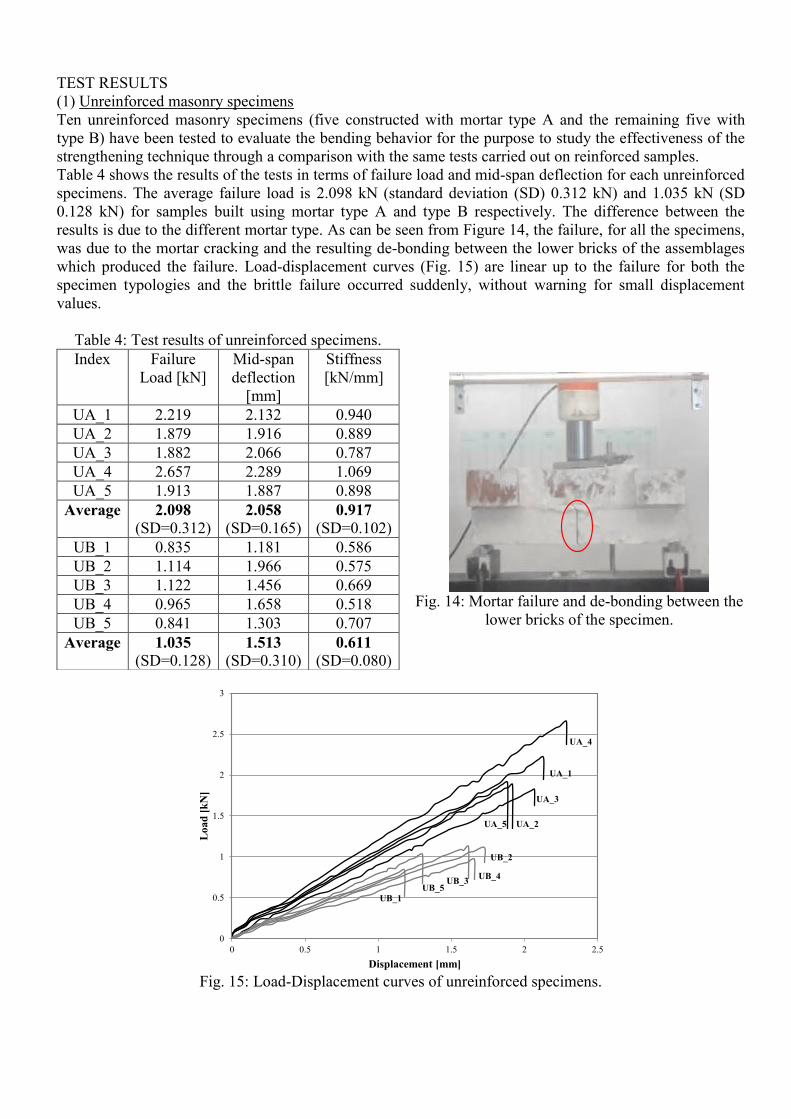
TEST RESULTS
(1) Unreinforced masonry specimens
Ten unreinforced masonry specimens (five constructed with mortar type A and the remaining five with
type B) have been tested to evaluate the bending behavior for the purpose to study the effectiveness of the
strengthening technique through a comparison with the same tests carried out on reinforced samples.
Table 4 shows the results of the tests in terms of failure load and mid-span deflection for each unreinforced
specimens. The average failure load is 2.098 kN (standard deviation (SD) 0.312 kN) and 1.035 kN (SD
0.128 kN) for samples built using mortar type A and type B respectively. The difference between the
results is due to the different mortar type. As can be seen from Figure 14, the failure, for all the specimens,
was due to the mortar cracking and the resulting de-bonding between the lower bricks of the assemblages
which produced the failure. Load-displacement curves (Fig. 15) are linear up to the failure for both the
specimen typologies and the brittle failure occurred suddenly, without warning for small displacement
values.
Table 4: Test results of unreinforced specimens.
Index Failure
Load [kN]
Mid-span
deflection
[mm]
Stiffness
[kN/mm]
UA_1 2.219 2.132 0.940
UA_2 1.879 1.916 0.889
UA_3 1.882 2.066 0.787
UA_4 2.657 2.289 1.069
UA_5 1.913 1.887 0.898
Average 2.098
(SD=0.312) 2.058
(SD=0.165) 0.917
(SD=0.102)
UB_1 0.835 1.181 0.586
UB_2 1.114 1.966 0.575
UB_3 1.122 1.456 0.669
UB_4 0.965 1.658 0.518
UB_5 0.841 1.303 0.707
Average 1.035
(SD=0.128) 1.513
(SD=0.310) 0.611
(SD=0.080)
Fig. 14: Mortar failure and de-bonding between the
lower bricks of the specimen.
Fig. 15: Load-Displacement curves of unreinforced specimens.
0
0.5
1
1.5
2
2.5
3
0 0.5 1 1.5 2 2.5
Load
[k
N]
Displacement [mm]
UA_4
UA_1
UA_5 UA_2
UA_3
UB_2
UB_4UB_3
UB_5
UB_1
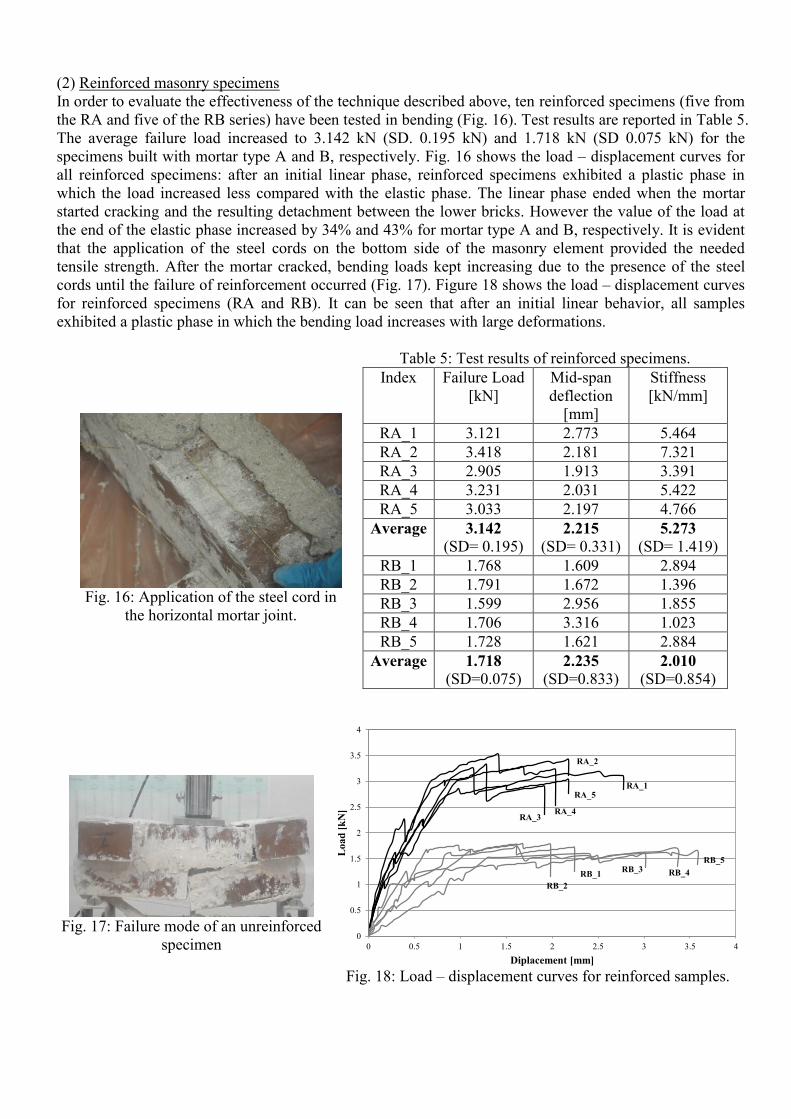
(2) Reinforced masonry specimens
In order to evaluate the effectiveness of the technique described above, ten reinforced specimens (five from
the RA and five of the RB series) have been tested in bending (Fig. 16). Test results are reported in Table 5.
The average failure load increased to 3.142 kN (SD. 0.195 kN) and 1.718 kN (SD 0.075 kN) for the
specimens built with mortar type A and B, respectively. Fig. 16 shows the load – displacement curves for
all reinforced specimens: after an initial linear phase, reinforced specimens exhibited a plastic phase in
which the load increased less compared with the elastic phase. The linear phase ended when the mortar
started cracking and the resulting detachment between the lower bricks. However the value of the load at
the end of the elastic phase increased by 34% and 43% for mortar type A and B, respectively. It is evident
that the application of the steel cords on the bottom side of the masonry element provided the needed
tensile strength. After the mortar cracked, bending loads kept increasing due to the presence of the steel
cords until the failure of reinforcement occurred (Fig. 17). Figure 18 shows the load – displacement curves
for reinforced specimens (RA and RB). It can be seen that after an initial linear behavior, all samples
exhibited a plastic phase in which the bending load increases with large deformations.
Fig. 16: Application of the steel cord in
the horizontal mortar joint.
Table 5: Test results of reinforced specimens.
Index Failure Load
[kN]
Mid-span
deflection
[mm]
Stiffness
[kN/mm]
RA_1 3.121 2.773 5.464
RA_2 3.418 2.181 7.321
RA_3 2.905 1.913 3.391
RA_4 3.231 2.031 5.422
RA_5 3.033 2.197 4.766
Average 3.142
(SD= 0.195) 2.215
(SD= 0.331) 5.273
(SD= 1.419)
RB_1 1.768 1.609 2.894
RB_2 1.791 1.672 1.396
RB_3 1.599 2.956 1.855
RB_4 1.706 3.316 1.023
RB_5 1.728 1.621 2.884
Average 1.718
(SD=0.075) 2.235
(SD=0.833) 2.010
(SD=0.854)
Fig. 17: Failure mode of an unreinforced
specimen
Fig. 18: Load – displacement curves for reinforced samples.
0
0.5
1
1.5
2
2.5
3
3.5
4
0 0.5 1 1.5 2 2.5 3 3.5 4
Lo
ad
[k
N]
Diplacement [mm]
RA_2
RA_1
RA_4
RA_5
RA_3
RB_1
RB_2
RB_5
RB_4RB_3
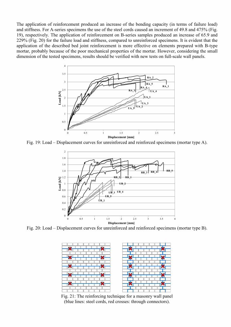
The application of reinforcement produced an increase of the bending capacity (in terms of failure load)
and stiffness. For A-series specimens the use of the steel cords caused an increment of 49.8 and 475% (Fig.
19), respectively. The application of reinforcement on B-series samples produced an increase of 65.9 and
229% (Fig. 20) for the failure load and stiffness, compared to unreinforced specimens. It is evident that the
application of the described bed joint reinforcement is more effective on elements prepared with B-type
mortar, probably because of the poor mechanical properties of the mortar. However, considering the small
dimension of the tested specimens, results should be verified with new tests on full-scale wall panels.
Fig. 19: Load – Displacement curves for unreinforced and reinforced specimens (mortar type A).
Fig. 20: Load – Displacement curves for unreinforced and reinforced specimens (mortar type B).
Fig. 21: The reinforcing technique for a masonry wall panel
(blue lines: steel cords, red crosses: through connectors).
0
0.5
1
1.5
2
2.5
3
3.5
4
0 0.5 1 1.5 2 2.5 3
Load
[k
N]
Displacement [mm]
UA_5UA_2
UA_3
UA_1
UA_4
RA_2
RA_1RA_5
RA_4
RA_3
0
0.2
0.4
0.6
0.8
1
1.2
1.4
1.6
1.8
2
0 0.5 1 1.5 2 2.5 3 3.5 4
Load
[k
N]
Displacement [mm]
UB_5
UB_2
UB_3
UB_1
UB_4
RB_2 RB_1
RB_5RB_4RB_3
Fig. 21 shows the application of the described reinforcing technique for a real-scale masonry panel: the
steel chords are applied on both faces of the element. However, the reinforcing elements are applied only in
the horizontal mortar joints on one side of the wall and in the other in both the horizontal and the vertical
joints. The steel cords applied are connected to the other face of the wall by using transverse stainless steel
connectors.
CONCLUSIONS
This research focused on the bending behavior of small brickwork assemblages reinforced by the insertion
of two high strength steel cords, applied into manually prepared voids and repointed with new mortar. Two
different lime based mortars have been used: one (type A) characterized by ratio sand/binder = 2/1 in
volume while the other (type B) by ratio sand/binder= 3/2 in volume. Twenty small specimens have been
built and tested in three-point bending.
The following conclusion can be drawn from the investigation:
The unreinforced specimens exhibited a linear-elastic behavior. The average bending capacity of
the samples realized with the mortar type A is approximately two times bigger than the specimens
realized with mortar type B.
Both unreinforced specimens are characterized by brittle collapse due to the mortar failure and the
resulting de-bonding between the lower bricks of the assemblages.
Application of the steel cords on the specimens manufactured with both mortar’s type produced an
increasing of the bending capacity on RA and RB samples. In particular, for A-series, the capacity
has increased by 49.8% while for the B-series the same parameter was 65.9% compared with the
respective unreinforced masonry assemblages. The reinforcement technique is more effective for
elements realized with the weakest mortar type.
For the reinforced assemblages, the elastic trend finish with the mortar failure and the de-bonding
between the lower bricks of the specimens, however, the maximum load at the end of the elastic
phase is higher compared with the unreinforced of 34% and 43% respectively for mortar type A and
B.
After the initial linear phase, the reinforced specimens exhibited a plastic phase in which the
bending load keep increasing up to failure of the steel cord which lost effectiveness for the
excessive bricks’ deformation but without breaking and the test finished with the failure of the
specimen.
Reinforced specimens exhibited an increment in flexural stiffness. In particular the highest increase
was for the specimens realized with mortar type A (475%) compared with the unreinforced ones.
For the specimens made with mortar type B stiffness increased of 229%.
Considering the small dimension of the tested specimens, the above conclusions should be verified
on specimens realized with larger dimensions.
ACKNOWLEDGMENTS
The authors would like to acknowledge the support of the Building & Construction Materials Lab at
Northumbria University for the use of test and measurement equipment critical to the collection and
evaluation of the data presented. The experimental program was carried out with the help of Hassan
Alhassan, undergraduate student. Authors are also grateful for help and support in the laboratory activities
to Christopher Walton, Matthew Dundas and Leon Amess.
REFERENCES
Corradi, M., Borri, A. and Vignoli A. (2002), “Strengthening techniques tested on masonry
structures struck by the Umbria-Marche earthquake of 1997-1998”, Construction and Building
Materials, Vol.16, 229-239.
Bayraktar, A., CoŞkun, N. and Yalçin A. (2007), “Damages of masonry buildings during the July 2,
2004 Doğubayazit (Ağri) earthquake in Turkey”, Engineering Failure Analysis, Vol. 13, 147-157.
Brandonisio, G., Lucibello, G., Mele, E. and De Luca A. (2013), “Damage and performance
evaluation of masonry churches in the 2009 L’Aquila earthquake”, Engineering Failure Analysis,
Vol. 34, 693-714.
D’Ayala, D.F. and Paganoni, S. (2011), “Assessment and analysis of damage in L’Aquila historic
city centre after 6th
April 2009”, Bulletin of Earthquake Engineering, Vol. 9, 81-104.
Vintzileou, E. and Tassios, T. (1995), “Three-leaf stone masonry strengthened by injecting cement
grouts”, Journal of Structural Engineering, Vol. 121, 848-856.
Binda, L., Modena, C., Baronio, G. and Abbaneo, S. (1997), “Repair and investigation techniques
for stone masonry walls”, Construction and Building Materials, Vol. 11, 133-142.
Schuller, M.P, Atkinson, R.H. and Borgsmiller, J.T. (1994), “Injection grouting for repair and
retrofit of unreinforced masonry”, Proc. 10th
International Brick and Block Masonry Conference
(IB2Mac), Calgary, Canada.
Sheppard, P. and Tercely, S. (1980), “The effect of repair and strengthening methods for masonry
walls”, Proc.7th
on World Conference on Earthquake Engineering (WCEE), Istanbul, Turkey, Vol.
6, 255-262.
Jabarov, M., Kozharinov, S. and Lunyov, A. (1980), “Strengthening of damaged masonry by
reinforcedmortar layers”, Proc.7th
on World Conference on Earthquake Engineering (WCEE),
Istanbul, Turkey, Vol. 6, 73-80.
Prawel, S.P., Reinhorn, S.P. and Qazi, S. (1988), “Upgrading the seismic resistence of unreinforced
brick masonry using ferrocement coating”, Proc. 8th
International Brick and Block Masonry
Conference (IB2Mac), London, UK.
Valluzzi, M.R. (2007), “On the vulnerability of historical masonry structures: analysis and
mitigation”. Materials and Structures, Vol. 40, 723-743.
Gilstrap, J.M. and Dolan, C.W. (1998), “Out-of-plane bending of FRP-reinforced masonry walls”,
Composites Science and Technology, Vol. 58, 1277-1284.
Bakis, C.E., Bank, L.C., Brown, V.L., Cosenza, E., Davalos, J.F., Lesko, J.J., Machida, A., Rizkalla,
S.H., Triantafillou, T.C. (2002), “Fiber-reinforced polymer composites for construction-state-of-
the-art-review”, Journal of Composites for Construction, Vol. 6, 73-87.
Papanicoulau, C.G., Triantafillou, T.C., Papathanasiou, M. and Karlos, K. (2008), “Textile
reinforced mortar (TRM) versus FRP as strengthening material of URM walls: out-of-plane cycling
loading”, Materials and Structures. Vol. 41, 143-157.
D’Ayala, D. (1998), “The use of bed joint reinforcement to improve the performance of historic
masonry buildings”, Proc. 5th
International Masonry Conference, Bath, UK.
Valluzzi, M.R., Binda, L. and Modena, C. (2005), “Mechanical behaviour of historic masonry
structures strengthened by bed joints structural repointing”, Construction and Building Materials.
Vol. 19, 63-75.
Borri, A., Castori, G. and Corradi, M. (2013), “Masonry confinement using steel cords”, Journal of
Materials in Civil Engineering, Vol. 25, 1910-1919.
Corradi, M., Borri, A., Giannantoni, A. and Speranzini, E. (2010), “Reinforcement of historic
masonry with high strength steel cords”, Journal of the International Masonry Society”, Vol. 23,
79-90.
Borri, A., Castori, G., Corradi, M. and Sisti, R. (2014), “Masonry wall panels with GFRP and steel-
cord strengthening subjected to cyclic shear: An experimental study”, Construction and Building
Materials, Vol. 56, 63-73.
EN 772-1:2011. Methods of test for masonry units. Determination of compressive strength.
EN 1015-11:1999. Determination of flexural and compressive strength of hardened mortar.